Emergence of a Barchan Belt in a Unidirectional Flow: Experiment and Numerical Simulation
Abstract
We observed time evolution of dune fields in a water tank experiment and simulated it by using a simple model without taking complex fluid dynamics into account. The initial sand bed changed its form into transverse ripples , that is, dunes with straight crest lines perpendicular to the flow direction. Then the crescentic shaped dunes called barchans emerged from transverse ripples.
Sand dunes, which are found in deserts, on the sea bottom and also on Mars, have various morphologic patterns. Dunes are formed by interactions between the flow (wind or water) and sand. The flow makes the shape of a dune by transporting sand particles. The dune topography, in turn, acts as a boundary condition on the flow. Types of sand dunes are determined by the amount of available sand and the variation of the flow[1]. When the flow is unidirectional and the amount of sand is abundant for covering the entire bedrock, dunes with straight crest lines perpendicular to the flow called transverse dunes are generated. When the flow is unidirectional but the amount of sand is insufficient, on the other hand, crescentic shaped dunes called barchans are formed. Barchans usually migrate as a group and form a barchan belt [2, 3]. The barchan belt is generated from a sand source which exists windward [2]. When there are transverse dunes windward which act as a sand source, a morphologic sequence of three types of dunes, transverse dunes, barchanoids and barchans from upwind to downwind is observed in deserts, where barchanoid is a dune with a wavy crest [4].
Observing the whole process of the formation dynamics of a barchan belt is quite difficult in general because time scale of the dynamics is very long. To overcome this difficulty, laboratory experiments using a water tank were proposed, [5, 6, 7, 8, 9] , which reduce the time scale of dynamics by less than a hundredth in rough estimates. Quite recently, a transition from transverse dunes to barchans was observed in a water tank under an oscillatory flow by Endo et. al.[7] A water tank experiment under an unidirectional flow was also conducted and a similar morphologic transition was observed[9].
Only a few studies on the barchan belt have been made theoretically or by numerical simulations. Lima et. al.[10] and Hersen et. al.[3] has studied the stability of a barchan belt, assuming that many barchans somehow formed. However, formation processes of the barchan belt from a sand source have not been discussed. Moreover their models have not taken into account a solitary wave behavior of barchans, which was found in collision dynamics[11, 12, 13]. In this letter, we will investigate formation dynamics of a barchan belt by using a numerical model, which has succeeded in reproducing a solitary wave behavior[12]. We also conduct a water tank experiment for the purpose of observing development of a barchan belt.


The experiment was performed in a water tank (10 m long, 20 cm wide and 50 cm deep) in which a pump can generate a steady unidirectional flow. Water depth 13.5 cm was kept constant. The sand was well-sorted: 80-100 in diameter and 130 g in total weight. In the initial condition, the sand bed was placed in an area of 15 cm long and 20 cm wide. Figure 1 shows the flow velocity measured at several different heights in a run without a sand bed. Since height of the sand bed was less than 1 cm, the transportation of sand was considered to occur inside the boundary layer.
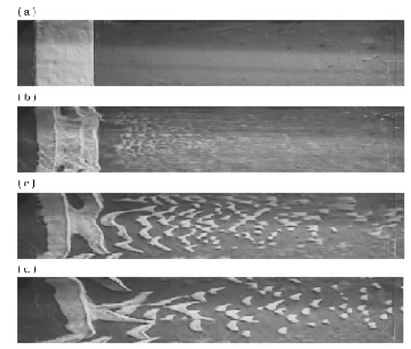
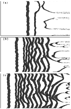
After the flow started, stages of morphologic transition were observed. First, instability on the sand bed grew and transverse ripples started to appear (Fig. 2(b)). Next, parts of the transverse ripples were breached at some places and the fragments eventually became barchans (Fig. 2(c) and 2(d) ). Figure 2(d) closely resembles a barchan belt in a real desert sketched by Bagnold[2].
Numerical simulation of a dune field taking into account complex process of flow dynamics and granular dynamics is a formidable task because of computational cost. In what follows, we used a simple model with minimal processes. Both complex fluid dynamical processes such as convection and viscosity and effect of size and shape of sand grain were ignored. This model has already succeeded in reproducing morphologic features of a single barchan and collision dynamics of two barchans[12].
In the model, the dune field is divided into square cells. [14, 15] Each cell is considered to represent an area of the ground which is sufficiently larger than the sand grains. A field variable which expresses the local surface height is assigned to each cell; denotes the discrete time step and the spatial coordinate and are positions of the center of a cell in the flow direction and in the lateral direction, respectively. The edge length of the cell is taken as a unit of length. In short, , and are discrete variables while takes a continuous value.
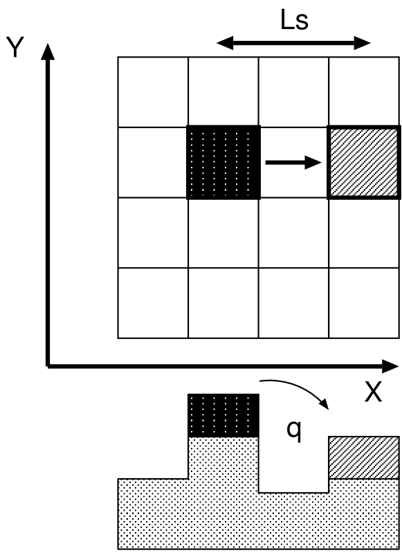
Next, we models a motion of sand grain considering only the following two processes: saltation and avalanche. Saltation is the transportation process of sand grains by the flow. The schematic diagram of the saltation is shown in Fig. 4. The saltation length and saltation mass are denoted and , respectively. Here, the saltation mass indeed is a volume of sand transfered from a cell to another cell. Since the area of a cell is unity, represents change of height of a cell by saltation. In each time step of a simulation, the saltation mass shifts from a cell to the leeward cell . Hence changes of height and take place at the taking-off cell and the landing cell, respectively. Saltation length is then modeled by the following equation:
| (1) |
The phenomenological parameters =1.0, =1.0 and =0.01 are used in this work. is rounded up to an integer as is shown in Fig. 4 . Equation (1) represents that the sand is transported farther away as height is higher, but not too far. Note that equation (1) is used only in the range in which is an increasing function of . The saltation mass is fixed as 0.1 for simplicity throughout the present work.
Avalanche, on the other hand, is the process in which the sand slides down along the steepest slope if it becomes steeper than the angle of repose. In this simulation, first, the cells are marked if the slope, which makes with the lowest of their nearest-neighbor cells, exceeds the angle of repose. Then half of the excess volume of each marked cell is transfered. Here the angle of repose is fixed as . This procedure is repeated until all cells satisfy the stability condition. Two processes of saltation and avalanche are performed by turns.
In the numerical field, the open boundary condition was imposed in the flow direction while the lateral boundary was impenetrable to sand grains. It means that there was no influx sand from the upwind boundary and sand which went out from the downwind boundary was simply deleted. The dune field consisted of 1052 (windward) by 512 (lateral) cells.
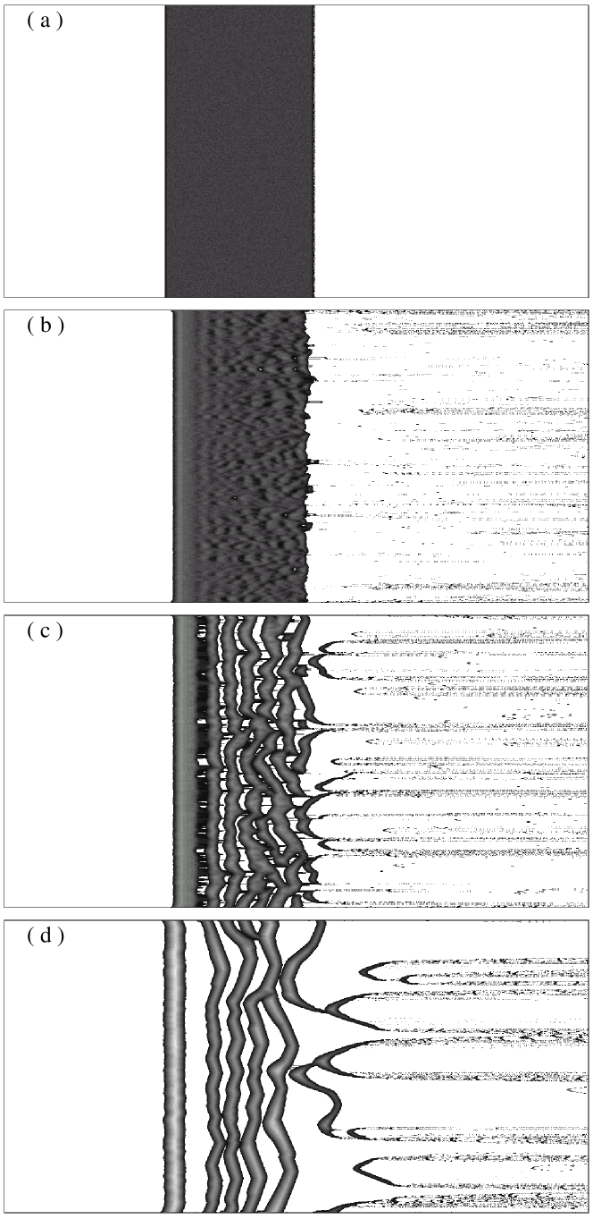
As an initial condition, we set a rectangular sand bed in order to reproduce the experimental situation. The initial sand bed had a sand depth , length along the flow direction and width (Fig. 5(a)). Height of the sand were then perturbed with 10 random noise.
After the simulation started, instability grew in the flow direction and made the sand bed change to transverse ripples. After a while, barchans emerged from the transverse ripples because of instability in the lateral direction (Fig. 5) . The processes quite similar to what were observed in the water tank experiment were thus reproduced.
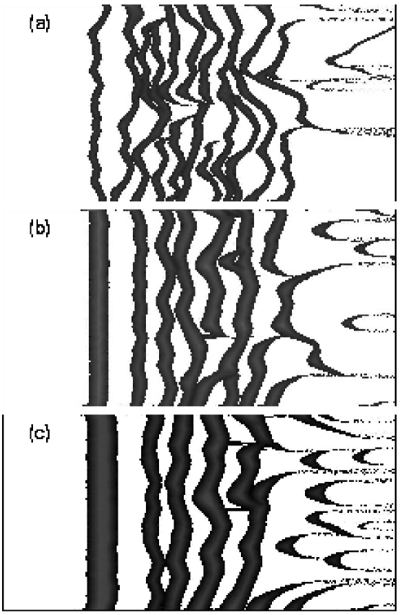
Next, we changed the sand depth and the length of the initial sand bed. As became shallower, ripples were found to be narrower (Fig. 6). As became larger, on the other hand, the width of ripples was unchanged but the number of ripples increased (Fig. 7). It means that the ripples have a characteristic length which depends on initial depth of the sand bed as long as is much larger than .
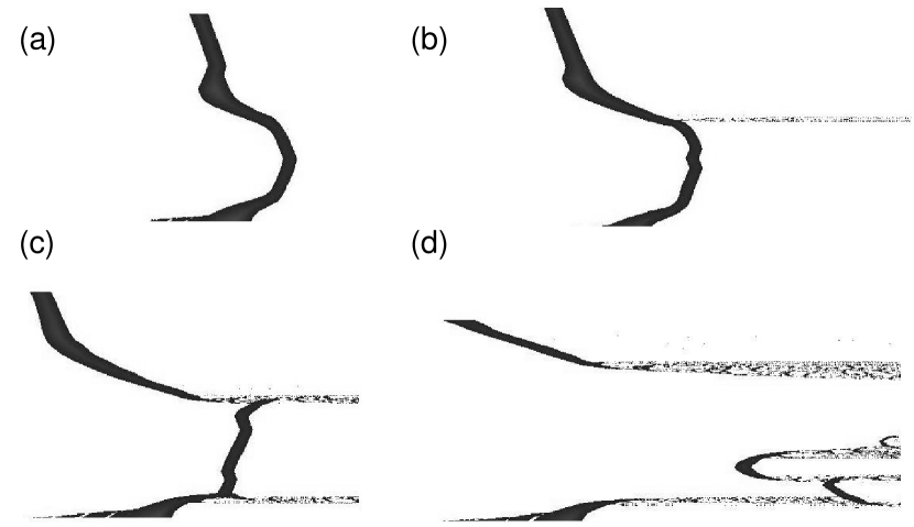
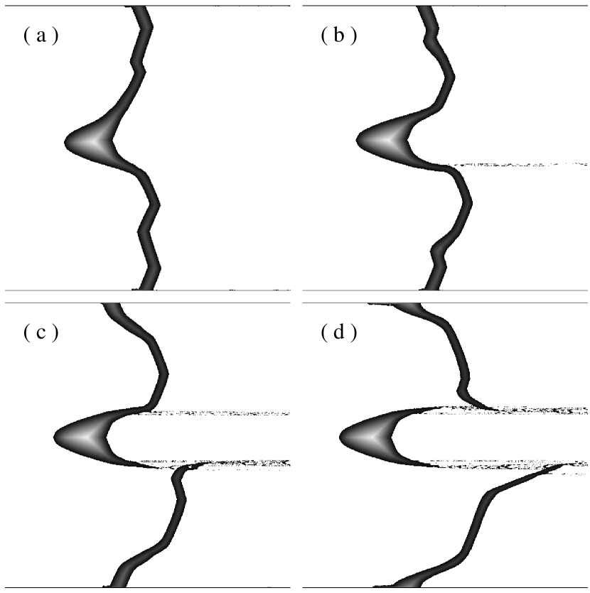
We observed two types of transition from transverse ripples to barchans. Type A, an example of which is shown in Fig. 8, occured when a portion of a transverse ripple happened to be much lower than the rest body. The transverse ripple gradually extended to the leeward at that part and eventually breached because the migration velociy is inversely proportional to the height[16, 17, 18]. After that, the fragment thus formed became a barchan. Transition of this type were also observed in the water tank experiment [9]. Type B, an exapmle of which is shown in Fig. 9, occured when a portion of a transverse ripple happened to be much higher than the rest body. The transverse ripple formed a crescent shape at that part, which evetually breached from a ripple to form an isolated barchan. In this case, a barchan appeared in the windward of the ripple. This type was observed only by the simulation so far. Whether or not this type can be observed in a water tank is left for a future work.
We found that in most cases, although not always, a portion of the sand escaped from a transverse ripple before a barchan emerged. This sand escape can also be seen in the water tank experiments, although it is not clear whether or not emergence of a barchan is always accompanied by the sand escape, because observing it is difficult unless the amount is large enough. The sand escape is a precursor of a barchan formation, so that it will be useful for locating the place where a barchan is emerging in natural dune fields.
In conclusion, we succeeded in simulating a dune field dynamics by using a simple model in a steady unidirectional flow. The model took only two processes into account: saltation and avalanche. The barchans emerged through transverse ripples from the initial sand bed. Before barchans formed from the transverse ripples, a portion of sand often escaped from the ripples.
We thank to H. Nishimori for useful discussion and K. Taniguchi for experimental support. This work was partially supported by the 21st Century COE Program named ”Towards a new basic science : depth and synthesis”.
References
- [1] R. J. Wasson and R. Hyde :Nature 304 (1983) 337.
- [2] R. A. Bagnold : The Physics of Blown Sand and Desert Dunes (Methuen, London, 1941).
- [3] P. Hersen, K. H. Andersen, H. Elbelrhiti, B. Andreotti, P. Claudin and S. Douady :Phys. Rev. E 69 (2004) 011304.
- [4] E. D. McKee : A Study of Global Sand Seas. (United States Government Printing Office, Washington, 1979).
- [5] Y. Nio and M. Barahona :Proc. Int. Assoc. Hydraul. Res. 27B (1997) 1037.
- [6] P. Hersen, S. Douady and B. Andreotti :Phys. Rev. Lett. 89 (2002) 264301.
- [7] N. Endo, H. Kubo and T. Sunamura: Earth Surf. Processes Landforms 29 (2004) 31.
- [8] N. Endo, K. Taniguchi and A. Katsuki :Geophysical Research Letters 31 (2004) 12503.
- [9] N. Endo, T. Sunamura and H. Takimoto :submitted to Earth Surf. Processes Landforms
- [10] A. R. Lima, G. Sauermann, H. J. Herrmann and K. Kroy :Physica A 310 (2002) 487.
- [11] V. Schwmmle and H. J. Herrmann :Nature 426 (2003) 619.
- [12] A. Katsuki, H. Nishimori, N. Endo and K. Taniguchi: preprint (cond-mat/0403312)
- [13] O. Duran, V. Schwaemmle and H. Herrmann: preprint (cond-mat/0406392)
- [14] B. T. Werner :Geology 23 (1995) 1107.
- [15] H. Nishimori, M. Yamasaki and K. H. Andersen :J. Mod. Phys. B 12 (1998) 256.
- [16] H. J. Finkel: Journal of Geology 67 (1959) 614.
- [17] P. A. Hesp and K. Hastings :Geomorphology 22 (1998) 193.
- [18] B. Andreotti, P. Claudin and S. Douady :Eur. Phys. J. B 28 (2002) 321.