The role of nitrogen related defects in high- dielectric oxides: density functional studies
Abstract
Using ab initio density functional total energy and molecular dynamics simulations, we study the effects of various forms of nitrogen post deposition anneal (PDA) on the electric properties of hafnia in the context of its application as a gate dielectric in field effect transistors (FET). We consider the atomic structure and energetics of nitrogen containing defects which can be formed during the PDA in various N-based ambients: N2, N, N, NH3, NO, N2O. We analyse the role of such defects in fixed charge accumulation, electron trapping and in the growth of the interface SiO2 layer. We find that nitrogen anneal of the oxides leads to an effective immobilization of native defects such as oxygen vacancies and interstitial oxygen ions, which may inhibit growth of silica layer. Nitrogen in any form effectively incorporates into the pre-existing oxygen vacancies and, therefore may decrease the concentration of shallow electron traps. However, nitrogen in any form is unlikely to significantly reduce the fixed charge in the dielectric.
pacs:
71.55.Ht, 81.05.Je, 71.15.MbI Introduction
Transistor scaling, which enables continuous increase of performance of integrated circuits, has been generally facilitated by a reduction in the thickness of the gate dielectric in typical metal oxide semiconductor field effect transistors (MOSFET). However, a further decrease of the thickness of conventional silicon dioxide (SiO2)-type dielectrics leads to an unacceptable rise in the gate leakage current, and hence, power consumption. Several possible solutions are under consideration Kingon et al. (2000), but one of the most attractive, which retains standard MOSFET design, is to replace SiO2 with a material of higher dielectric constant (high-). The resulting increase in effective capacitance means that a thicker gate dielectric layer can be used, reducing gate leakage current, while providing comparable performance to a much thinner SiO2 layer. The choice of specific high- material is subject to rather strict electrical and process integration requirements Huff et al. (2003) eliminating most of the potential candidates, and presently hafnium oxide-based dielectrics are considered to be the most promising from a practical standpoint.
In spite of recently reported successes Chau et al. (2003), the performance of high- transistors requires further improvement to meet the industry needs for most of the potential applications. Most critically, high- devices suffer from poor channel mobility Wilk et al. (2001); Wong (2002); Young et al. (2004, 2003) and instabilities of the threshold potential (VT) Kerber et al. (2003); Carter et al. (2003). It is understood that these drawbacks result from the high density of structural defects in the high- films Bersuker et al. (2004a), in particular, defects acting as electron traps Stesmans and Afanas’ev (2004); Afanas’ev and Stesmans (2002); Houssa et al. (2002). These defects were shown to form localized states in the band gap, whose occupancy may vary with the external chemical potential Foster et al. (2002a, b); Shluger et al. (2003). It was generally expected that a post deposition anneal (PDA) would reduce the density of intrinsic defects. However, for high- films deposited on silicon, PDA usually results in a decrease of the effective capacitance of the gate stack. This decrease was attributed to a spontaneous growth of the SiOx buffer layer between high- and silicon substrate during the high- film deposition and subsequent anneals (600 - 1000 C), facilitated by the oxygen excess. The low quality of the resulting interfacial SiOx layer negatively impacts transistor characteristics Bersuker et al. (2004b). In order to suppress the suboxide growth, nitrogen rich ambients are preferable in the PDA Wilk et al. (2001). In general, nitrogen incorporation into the Hf-based dielectrics was shown to provide several advantages - reducing boron penetration from the p-type poly silicon gate electrodes, improving electrical performance and increasing stability of high- devices. Besides N2 PDA, several other options were used to increase nitrogen incorporation in Hf-based oxides, including remote nitrogen plasma (N) Hinkle and Lukovsky (2003), ammonia (NH3), nitrogen monoxide (NO), and N2O, as well as nitrato-CVD deposition processes Afanas’ev and Stesmans (2004a, b). However, the lack of understanding of forms of nitrogen incorporation and its effect on the electronic properties of the dielectric hampers further progress.
In this paper we theoretically investigate the incorporation of N2, N, NO, NH3 species in different charge states into the ideal and defective HfO2 crystal. Specifics of the structural and chemical composition of real films depend strongly on the deposition and PDA conditions. In particular, a thin film deposited at relatively low temperatures (typically below 500 K) is in a metastable porous low density state, often characterized by substantial non-stoichiometry. Significant efforts have been recently made to resolve the atomic structure of the deposited films Stemmer and Schlom (2003); Opila and Eng Jr (2002). After PDA in oxygen (T > 770 K), hafnia films on Si adopt the monoclinic structure Balog et al. (1977); Aarik et al. (2000); Neumayer and Cartier (2001). This is in contrast with zirconia which may crystallize into either monoclinic or tetragonal structure depending on the film thickness and stoichiometry Stemmer and Schlom (2003). In this paper we leave the problem of polymorphism aside, and focus on monoclinic hafnia.
In broad terms, an optimal post deposition anneal should stipulate:
-
•
formation of dense (preferably amorphous) oxide films with controlled thickness, high dielectric constant and high thermal stability;
-
•
reduction of fixed charge and electron traps in the bulk of the film and at the interface with Si (high electrical stability)
-
•
an effective control over the growth of the SiO2 buffer layer;
-
•
inhibition of the diffusion of charged species towards the interface and into the channel region.
In order to assess the effectiveness of different anneals, we assume the following physical picture. After deposition and PDA, a hafnia film is crystallized into the monoclinic phase which may still contain a significant concentration of oxygen vacancies and interstitials. In the significantly non-stoichiometric films either oxygen interstitials (oxygen excess) or oxygen vacancies (oxygen depletion) will dominate. Nitrogenous species introduced by the PDA, diffuse into the bulk oxide and take part in the following (not necessarily sequential) processes: i) incorporation in the lattice interstitials or replacement of lattice oxygen ions; ii) dissociation into other species both in interstitial and in regular lattice sites; iii) reaction with the existing oxygen vacancies and interstitial oxygen species.
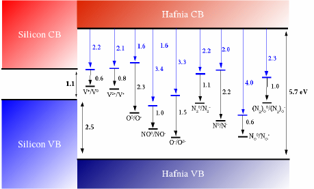
The nitrogen defects thus formed may be neutral with respect to the lattice or themselves form fixed charge or charge trap centres. This would depend on the position of the corresponding defect levels with respect to the band edges of Hafnia and Silicon and with respect to the Fermi-level (see Fig. 1). The latter in the n-channel devices is located near the silicon conduction band minimum (CBM).
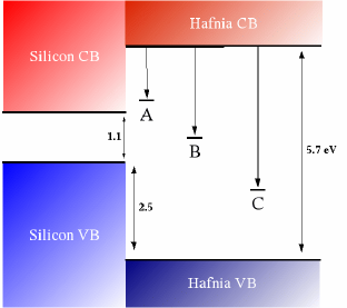
All the electrically active defects in the oxide layer can be qualitatively classified by the position of their levels with respect to the silicon band edges:
A) Defects whose levels are resonant with the Si conduction band. Under zero electric field and in the thermodynamic equilibrium these levels are empty. However, such states are available for resonant tunneling at non-zero gate voltage, and thus may serve as electron traps.
B) Defects whose levels fall into the silicon band gap. The electron occupancy of such defects depends on the position of the Fermi level. These deep defects are responsible for the Fermi-level pinning, and thus, for the high threshold voltages. Also they may contribute into threshold potential instability and, to some extent, to a fixed charge problem, since the charge relaxation time on such defects may be macroscopically slow.
C) Defect states resonant with the silicon valence band are expected to be occupied, and, depending on their charge with respect to the lattice, they may become a major source of the fixed charge.
Therefore, the efficiency of a specific PDA could be judged by the integral effect of the resultant nitrogen contained species on the bulk charge trap density, and on the mobility of oxygen, which may occur via the vacancy or interstitial mechanisms Foster et al. (2002b).
Although the model outlined above is certainly simplified, it will form a framework for systematizing the effect of various nitrogenous species on the properties of monoclinic hafnia. It can be then refined to include other important effects e.g. interface diffusion and segregation, impurity clustering etc.
In the next section we give the details of the calculations. The results of the modeling of the effect of different anneal gases are presented in section III and discussion is given in the last section.
II Calculation procedure
All the calculations were performed using the VASP code Kresse and Furthmüller (1996a, b), implementing spin-polarized Density Functional Theory (DFT) and the Generalized Gradient Approximation of Perdew and Wang Perdew et al. (1992) known as GGA-II. The plane wave basis set was used in conjunction with the ultra-soft pseudopotentials of Vanderbilt type Vanderbilt (1990). The standard pseudopotentials for hydrogen, hafnium, nitrogen, and oxygen atomic cores were generated with charges +1,+4,+5, and +6 respectively Kresse and Hafner (1994).
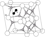
Bulk hafnia at atmospheric pressure and low temperature has monoclinic symmetry Ruh and Corfield (1970); Adams et al. (1991) (space group ). At T = 2000 K it undergoes martensitic phase transformation into the tetragonal phase (space symmetry ), and above T = 2870 K the cubic fluorite structure is most stable (space symmetry ). The monoclinic structure is characterized by the two non-equivalent anion sublattices (Fig. 2). In one, oxygen ions are 4-fold coordinated, and in another they are 3-fold coordinated. The equilibrium O-Hf distances range between 2.14 and 2.24 Å in the former and between 2.05 and 2.14 in the latter sublattice. These structural parameters are well reproduced using DFT and pseudopotentials described above and are discussed in detail in ref Shluger et al. (2003).
The calculations were made using a 96 atom unit cell, which is a extension of the 12 atom monoclinic primitive unit cell. We used two -points in the irreducible part of the Brillouin zone and a cutoff energy of 400 eV for atomic relaxation and total energy calculations. The total energies of the charged systems were corrected for the spurious electrostatic interaction arising from the periodic boundary conditions Leslie and Gillan (1985); Kantorovich (1999).
To test the stability of atomic configurations optimized in static calculations and to extract dynamical information, such as diffusion paths and vibrational frequencies, we carried out an extensive set of Born-Oppenheimer molecular dynamics (MD) simulations using VASP. In these simulations we used =0 and 300 eV energy cutoff and a constant volume, energy and number of particles (NVE) algorithm with a time step of 1 fs. This assured a total energy drift of less than 0.05 eV at T = 600 K for a typical MD run of 5 ps. The supercell volume in all calculations was fixed to its 0 K theoretical value Shluger et al. (2003).
For each charge state of a candidate defect () we first determine its geometric structure and formation or incorporation energy () using the static DFT calculations. Given the macroscopically long defect diffusion and charge relaxation times Carter et al. (2003), we believe that the defect equilibrium Free energies do not necessarily reflect relative concentrations of various defects (even if the Fermi level and atomic chemical potentials were well defined). Thus, we do not discuss free energies, but rather assume initially that all energetically stable charge states are possible, and then discuss most probable charge states considering there relative electron affinities of the defects.
The position of defect electrical levels with respect to the CBM of hafnia and silicon determines the stability of a defect in a particular charge state as well as its ability to trap or release an electron. These properties are quantified by the vertical and relaxed defect ionization energies (), and vertical electron () and hole () affinities, which are calculated using the approach described in ref. Foster et al. (2002a) (see Appendix for details). This approach is based on standard definitions of electron affinities and ionization energies, it employs combinations of total energies of the system in different charge states and conserves the number of electrons. In order to discuss the electron and hole trapping by defects from silicon, we neglect the band bending at the interface and the effect of applied voltage and use the experimental band offsets between bulk hafnia and silicon Afanas’ev et al. (2002); Afanas’ev and Stesmans (2004b).
Towards the full picture of possible products of incorporation of nitrogen, we examine all possible dissociation channels for nitrogenous molecular species in hafnia matrix. This is done by calculating their dissociation energy into various products. The latter is found as the difference of total energies for the system with the associated defect and the joint energy of the infinitely separated dissociation products, corrected for double counting of the perfect supercell term. In further discussion we treat a molecular defect as thermodynamically unstable if its dissociation is exothermic.
III Results of Calculations
As discussed previously, nitrogen-based PDA can be performed using a variety of gas sources (ambients), and depending on the chemical composition, pressure and temperature, different products may occur in the bulk film. Here we consider each PDA ambient in turn, and predict the likely resultant defects and their effects on the properties of the oxide.
III.1 Molecular Nitrogen
III.1.1 N2 incorporation
The experimental dissociation energy of an N2 molecule in the gas phase is 9.9 eV Kutzler and Painter (1988) (10.0 eV in our DFT calculations). Thus, no N2 dissociation is likely to occur at the surface, and molecular nitrogen is expected to diffuse inside the bulk oxide. Indeed, as we show below, even trapping of extra electrons or interaction with oxygen vacancies does not lead to a spontaneous dissociation of N2 molecular species inside the oxide.
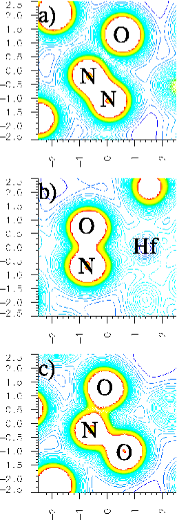
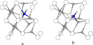
The equilibrium configuration of the neutral interstitial nitrogen molecule is shown in Fig. 2. The incorporation energy for this configuration with respect to N2 in the gas phase is 3.0 eV per nitrogen atom. It is seen in figures 2 and 3(a) that the interstitial N2 does not form a bond with the lattice oxygen, but rather incorporates in the interstitial space near to the three-fold coordinated oxygen site. This is in contrast with the O2 molecule, which makes a covalent bond with the lattice anion Foster et al. (2002a).
The interstitial N2 molecule has a positive affinity to two electrons (defect electron affinities are given in Table 1). The localization of the first extra electron on the N2 interstitial (N radical) results in the outward relaxation of the nearest neighbor oxygen ions (cf. O-N distance of 1.96 Å in N and 2.20 Å in N). The corresponding relaxation energy is 1.2 eV. The second extra electron is also strongly localized on the N molecular ion. This further increases the O-N distance to 2.34 Å with a relaxation energy of 0.6 eV with respect to the N geometry. Interestingly, a hole (an absence of the electron) in HfO2 will not localize on the N2 interstitial, owing to the fact that the last occupied orbital of the molecule is well below the valence band maximum (VBM).
| N- | 5.0 | - | 0.7 |
| N0 | 5.3 | 4.2 | 0.3 |
| N+ | 5.6 | 4.1 | 0.1 |
| N2+ | - | 5.0 | - |
| N | 4.2 | - | 1.5 |
| N | 4.3 | 3.4 | 1.3 |
| N | - | 3.3 | - |
| NO0 | 4.8 | 4.4 | 0.7 |
| N | 5.2 | - | 0.5 |
| N | 5.6 | 4.6 | 0.1 |
| N | - | 5.2 | - |
| (N2) | 3.9 | - | 1.7 |
| (N2) | 4.4 | 3.3 | 1.1 |
| (N2) | - | 3.8 | - |
III.1.2 Thermodynamic considerations on the likely charge states
We have established that interstitial nitrogen molecules may have multiple charge states, whose occurance at thermodynamic equilibrium is defined explicitely by the electron chemical potential. The latter depends not only on the external potential, but also on the concentrations and electrical levels of all other defects present in the lattice. In this case, the problem of the possible defect charge states may be evaluated by considering relative electron affinities of various defects, and answering the question: given the fixed number of electrons, on which of the defects they are more likely to reside? This question can be resolved by considering the electron exchange reactions between the pairs of infinitely separated defects as presented in Table 2.
| No | Reaction | Energy (eV) |
|---|---|---|
| 1 | 1.1 | |
| 2 | 2.4 | |
| 3 | 0.5 | |
| 4 | 0.7 | |
| 5 | 0.1 | |
| 6 | 0.6 | |
| 7 | 1.3 | |
| 8 | 1.4 | |
| 9 | 1.5 | |
| 10 | -0.4 | |
| 11 | -0.5 | |
| 12 | 1.2 | |
| 13 | 1.7 | |
| 14 | -0.2 | |
| 15 | 0.3 | |
| 16 | 0.3 | |
| 17 | 0.6 | |
| 18 | 1.2 | |
| 19 | 0.3 | |
| 20 | 0.6 | |
| 21 | 0.1 | |
| 22 | 0.1 | |
| 23 | 2.8 | |
| 24 | 2.7 |
Consider for example the oxygen Frenkel pair (an interstitial atom and the vacancy). It is evident from reactions (2.1,2) that in the overall neutral m-HfO2 the zero temperature equilibrium state corresponds to the doubly positively charged vacancies and doubly negatively charged interstitial oxygen atoms. Next, consider N2 interstitial molecules. Reactions (2.3-6) suggest that they are more electronegative then anion vacancies. Therefore, in oxygen deficient films (high concentration of vacancies) nitrogen molecules will be predominantly doubly negative, while the vacancies remain doubly positive.
In the case of oxygen excess (large concentrations of interstitials), the relative charge state is defined by the energy balance in the reactions (2.11-13). It follows that interstitial oxygen ions are more electronegative than nitrogen molecules. However, as discussed above, N is not stable, so nitrogen interstitial molecules will remain largely neutral in this case.
Finally, reaction (2.21) suggests that neutral and doubly negative N2 interstitials are only marginally preferable over the N.
The energetics of the electron exchange reactions considered in Tab. 2 allows to narrow down the range of relevant association/dissociation reactions between various pairs of defects considered below.
III.1.3 N2 reactions with interstitial oxygen species
First, we observe that the interstitial oxygen molecules (O2) are either marginally stable or unstable in any charge state (Table 3.1-4). Therefore, we conclude that excess oxygen is present only in the form of atomic interstitials. As demonstrated in refs. Szymanski et al. (2001); Crocombette (1999); Foster et al. (2001, 2002a), an interstitial oxygen atom forms a dumbell type configuration in silica, zircon, zirconia and hafnia where an oxygen atom effectively incorporates into the Me-O-Me bond (Me is Si, Zr or Hf ion) forming a Me-O-O-Me configuration with a O-O covalent bond (1.5 Å in HfO2).
Second, it follows from the calculations that both N2 and oxygen interstitials may accept charge states 0,-1,-2 with respect to the lattice (Table 1). Their likely association product, the N2O interstitial, is stable only in charge states (+2,+1,0). Next, it follows from the electron exchange reactions shown in Table 2.11-13 that oxygen interstitials are more electronegative than nitrogen molecules. Therefore, relevant reactions involving N2 and O must have nitrogen molecules in the charge state not more negative than that of the oxygen. Disregarding also reactions involving unstable initial or final charge states leaves only one possible association reaction (Table 3.5), which is endothermic. Therefore, the formation of neutral N2O interstitials is unfavorable. Similarly, it is kinetically unlikely that interstitial NO is formed from N2 molecules, since all reactions involving N2 dissociation (e.g. 3.6) are strongly endothermic. The fact that the N2 molecules do not bond to the interstitial oxygen atoms suggests that molecular nitrogen is ineffective in inhibiting diffusion of highly mobile oxygen interstitials Foster et al. (2002b) and in preventing them from migration towards the interface. This finding is consistent with experimental evidence that oxygen abundant deposition techniques lead to the formation of the SiO2 buffer layer at the HfO2/Si interface, and that the N2 PDA does not significantly affect its thickness Carter et al. (2003); Kerber et al. (2003).
| No | Reaction | Energy (eV) |
|---|---|---|
| 1 | -1.0 | |
| 2 | -0.3 | |
| 3 | 0.7 | |
| 4 | 0.0 | |
| 5 | -0.9 | |
| 6 | -2.1 | |
| 7 | 1.0 | |
| 8 | 1.2 | |
| 9 | 1.6 | |
| 10 | 1.5 |
III.1.4 N2 reactions with oxygen vacancies
In the case of substantial oxygen vacancies concentration in the film, the N2 interstitial species can interact with the vacant oxygen sites and passivate them. Based on the previous calculations Foster et al. (2002a); Shluger et al. (2003), we assume three-coordinated oxygen vacancies to dominate. We consider the stability of nitrogenous species in the three-coordinated anion lattice sites with respect to the infinitely separated interstitial species and the oxygen vacancy. Furthermore, we recall that nitrogen interstitial molecule is more electronegative than the oxygen vacancy (see Table 2) and discuss reactions involving doubly charged vacancies () as the most thermodynamically probable. The corresponding reaction energies are summarized in Table 4, where the subscript denotes the specie incorporated into the oxygen vacancy. Note, that the superscript denoting the charge state corresponds to the charge with respect to the lattice, which differs from the molecular charge in case of the substitute molecules. For example, the charge localized at the N2 molecule (nuclear plus electron) in the rhs of the reaction (4.1) is -2, so this defect is isovalent to the host O– ion, and thus, is neutral with respect to the lattice. Similarly in the rhs in (4.2) denotes the N substitution, which is in a charge state +1 with respect to the lattice.
| No | Reaction | Energy |
|---|---|---|
| 1 | 5.1 | |
| 2 | 4.7 | |
| 3 | 5.4 | |
| 4 | 2.2 | |
| 5 | 4.3 | |
| 6 | 3.3 | |
| 7 | 5.7 | |
| 8 | 6.1 | |
| 9 | 6.9 | |
| 10 | 6.6 | |
| 11 | 2.7 |
One can see that most of the stable interstitial species react with the pre-existed anion vacancies with a very substantial energy gain. Reactions 4.1,2 correspond to a formation of N2 molecule at the oxygen site, which is structurally similar to the O-N complex formed by the nitrogen atomic interstitial (see below and Fig. 3(b)). It is interesting to note, that the (N2)O is stable in three charge states +1,0,-1. It is evident that formation of the negative (N2)O substitution involves either pre-existing neutral vacancies (vacancies with 2 trapped electrons), or an electron(s) trapping by the neutral substitution. Although such processes are even more energetically favorable (e.g. 4.3), they might be kinetically inefficient due to the much lower mobility of the V0 and V+ as compared to V++.
Adding/removing an electron to/from the (N2)O just increases/decreases the N-N bond length and decreases/increases the nearest neighbor Hf-N bonds. The electron affinity of N2 at the oxygen vacancy is similar to that of the interstitial molecule (Table 1).
The energy gain in the interstitial-vacancy reactions shown in Table 4 may be compared with the formation energy of the oxygen Frenkel pair in different charge states (8.1, 7.0 and 5.6 eV for the (V0 - O0), (V+ - O-), and (V++ - O) pairs respectively Foster et al. (2002a)). It follows that, although the substitution of site oxygen ions by nitrogen molecules is endothermic, the substitution energies can be as low as 0.4 eV (as for N molecular ions), so the processes involving oxygen replacement by nitrogen are possible at elevated temperatures.
We note that the reactions involving different charge states of the vacancy can be readily calculated but they are likely to be even more exothermic due to a less stable left hand side (e.g. reaction (4.3).
III.2 Atomic Nitrogen
As already mentioned, a dissociation of the N2 molecule in the gas phase costs about 10 eV. However, this energy is greatly reduced in the bulk of hafnia crystal. Table 5 summarizes all possible reactions which would lead to the dissociation of N2. In reactions (5.1,2) we see that dissociation of the neutral molecule within the crystal is still endothermic, requiring about 3 eV for both neutral and charged products. The dissociation energy of the N molecular ion, although smaller, is still 1.6 eV (5.3,4). Thus, even without considering the reaction barriers, the dissociation of the nitrogen molecule seems highly unlikely even at elevated temperatures. We also find that, similarly to the N2 interstitial species, the N2 species trapped by oxygen vacancies are stable with respect to dissociation. The corresponding reactions (5.5-11) refer to N2 species in the oxygen vacancy on the left and to one of the product species in the vacancy and another in the interstitial position on the right. As one can see, all dissociation reactions considered in Tab. 5 are endothermic, hence, trapping of N2 in the oxygen vacancy does not significantly reduce its dissociation energy. From this, one may infer that after N2 PDA, the concentration of atomic or ionic nitrogen in the bulk film will be negligible.
| No. | Reaction | Energy (eV) |
|---|---|---|
| 1 | -3.1 | |
| 2 | -3.1 | |
| 3 | -2.2 | |
| 4 | -1.1 | |
| 5 | -2.9 | |
| 6 | -3.4 | |
| 7 | -4.4 | |
| 8 | -2.1 | |
| 9 | -2.5 | |
| 10 | -4.7 | |
| 11 | -3.6 |
However, atomic nitrogen can be introduced into the system by the plasma assisted nitridation Hinkle and Lukovsky (2003) (N), or using metal- nitride precursors in the film deposition Afanas’ev and Stesmans (2004a). Therefore, we consider next the energetics of the atomic nitrogen species.
III.2.1 N atom incorporation
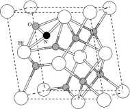
The interstitial nitrogen atom in its ground state configuration makes a covalent bond with the three-fold coordinated lattice oxygen. This ’dumbell’ structure is similar to that of the interstitial oxygen atom discussed previously in zircon Crocombette (1999), zirconia Foster et al. (2001) and hafnia Foster et al. (2002a). The structure of the defect is shown in Fig. 4, and the corresponding electron density is depicted in Fig. 3(b). The electronic ground state is a doublet. This is in contrast with atomic nitrogen in vacuum, whose quadruplet ground state is almost 3 eV lower than the doublet. An additional electron also fully localizes on the O-N bond with an affinity of 4.3 eV, increasing the bond length by about 0.1 Å. The relaxation energy after the electron trapping is about 1.2 eV, compared to over 2 eV for interstitial oxygen. In contrast to the N2 molecule and an atomic oxygen, the atomic nitrogen interstitial has no affinity for a second electron. However, atomic nitrogen is also stable as a positive ion. The local relaxation in this case is distinctly different (Fig. 3(c)). The nitrogen-oxygen pair is now very electron deficient, and in fact nitrogen forms a weak bond with a second lattice oxygen (N-O bonds are 1.46 and 1.59 Å). This is accompanied by an energy gain of 1.2 eV. Removal of another electron forces the nitrogen to a symmetric position, with two strong equivalent bonds (1.40 Å) to lattice oxygen sites and an energy gain of 0.6 eV. Thus interstitial atomic nitrogen may exist in monoclinic hafnia in four stable charge states (+2,+1,0,-1).
III.2.2 N reactions with interstitial oxygen species
In contrast with the N2, an atomic nitrogen binds to an oxygen interstitial with an energy gain of around 1.0-1.5 eV depending on the charge state (Table 3.7-10). This process is associated with the breaking of the O-O bond of the ’dumbell’ and formation of the NO2 quasi-molecule (Fig. 5b). The O-O distance is now 2.2 Å (cf. 1.5 Å in the neutral dumbell Foster et al. (2002a)), while the two N-O bonds are 1.3-1.4 Å. Interestingly, in this configuration there is no clear distinction between the interstitial and the site oxygen - the local symmetry for both oxygen ions remains similar. The energy gain in reactions of charged oxygen and nitrogen interstitial atoms is even greater (reactions 3.9,10). Note however that in contrast with N2, the electronegativity of the atomic interstitial is very close to that of the oxygen (2.14-18), so N and O interstitials are expected to have similar charges.
The stability of the interstitial NO molecular species suggests that atomic nitrogen may play an important role in immobilizing fast diffusing oxygen interstitials, especially O-, thereby inhibiting the growth of the unwanted SiO2 interfacial layer during anneal.
III.2.3 N reaction with oxygen vacancies
In considering reactions with vacancies we recall that the interstitial atomic nitrogen may accept the charge states +2, +1, 0, -1, the anion vacancy - +2, +1, 0, and the atomic nitrogen substitution: +1,0,-1. We also take into account the result that the nitrogen interstitial is substantially more electronegative than the vacancy, so the relevant reactions involve nitrogen in a charge state not more positive than that of the vacancy. These considerations leave five relevant reactions shown in Table 4.4-9. Similarly to N2, atomic nitrogen passivates the neutral vacancy with an excess energy in the range of 2-6 eV. One should also expect the vacancy passivation by atomic nitrogen to be more effective kinetically due to a higher mobility of atomic versus molecular nitrogen. Notice, however, that for the same reason reactions involving V++ will be faster than those with V+ or V0 as discussed before.
The nitrogen atom incorporation into the vacancy causes marginal outward relaxation of the three nearest Hf ions. A nitrogen atom at a vacancy has the highest electron affinity of any of nitrogen defects (see Table 1). The addition of an electron (in other words N- incorporation) causes the N-Hf bond lengths to become smaller than the O-Hf distance in the perfect lattice. The corresponding relaxation energy is about 0.6 eV. For N+ substitution the reverse relaxation occurs, i.e. the bond lengths increase, but with a similar energy gain.
An interesting and potentially important feature of both the nitrogen atom and molecule incorporated in an oxygen site is that both species can exist in the negative charge state. This means that the oxygen vacancy with N or N2 in it can effectively accommodate three electrons and the third electron is strongly bound see (Table 1).
On the other hand, our DFT calculations do not predict any electron affinity for the neutral oxygen vacancy in hafnia (see refs. Foster et al. (2002c, a) for discussion). Thus the formation of negatively charged centers is stipulated by the large electron affinity of nitrogen species. Together with interstitial nitrogen species, these centers can serve as deep electron traps and be responsible for the negative oxide charging.
However, the existence of negatively charged nitrogen species may have also some positive effect as they interact with protons. For example, reaction 6.5 clearly shows that it is energetically favorable for the interstitial N- to trap the proton and form a neutral NH interstitial. Since atomic nitrogen has a high electron affinity, and is likely to exist in the negative charge state, this provides a method for removing excess charge in the oxide due to protons - a problem often seen in experimental studies Houssa et al. (2002). However, the small energy gain of -0.6 eV for the reaction implies the possibility of some NH dissociation at higher temperatures.
| No | Reaction | Energy (eV) |
|---|---|---|
| 1 | -0.8 | |
| 2 | -1.6 | |
| 3 | -1.7 | |
| 4 | -0.3 | |
| 5 | -0.8 | |
| 6 | 0.1 |
III.3 Properties of NO and N2O in hafnia
Our calculations of the interaction of N and N2 with excess oxygen in the oxide have established that an NO interstitial binds with lattice oxygen sites. Reaction 3.5 viewed from right to left clearly suggests that N2O molecules are likely to dissociate into neutral or charged N2 species and oxygen interstitials. It is likely that nitrogen dioxide (NO2) will also dissociate to produce NO and oxygen interstitials. Therefore, PDA using nitric oxide, dinitric oxide, or nitrogen dioxide ambients will not be efficient in trapping oxygen and in preventing growth of SiOx buffer layer at the interface.
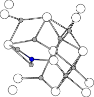
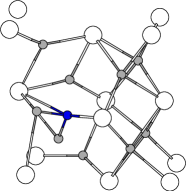
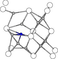
According to our calculations, the NO interstitial is a deep centre with an ionisation potential and electron/hole affinity similar to those of the N interstitial (c.f. Table 1). Being an open shell molecule, it is also stable in three charge states (+1,0,-1). The positive or negative charging of this molecule is associated with a large and not trivial lattice relaxation (Figure 5). As discussed in the previous section, an NO interstitial bonds to the 3-coordinated lattice oxygen, forming an NO-like configuration at the site. The orientation of this configuration is strongly coupled to its charge state. The angle also changes from 115∘ for a positive molecule to 108∘ for the neutral, to 103∘ for the negative molecule. The relaxation energy upon ionization is 1.3 eV, and that upon an electron trap is 1 eV, confirming the strong structural rearrangement.
NO and N2O molecules can interact with anion vacancies by incorporating with their oxygen end into the vacancy. The structure of the resulting defects is equivalent to that of atomic and molecular nitrogen interstitials discussed earlier in the paper.
Nitrogen interstitial atoms can trap interstitial oxygen according to reactions 3.7-10. However, the contribution of this sequence of reactions is likely to be small since it requires an initial vacancy as a catalyst.
III.4 Incorporation, diffusion and dissociation of NH3
Apart from its usage for PDA of hafnia films, incorporation of ammonia into oxides is an interesting example of a complex molecular defect. We shall start with the assumption that ammonia incorporates into the monoclinic hafnia lattice intact. However, we shall see, that such states are metastable and more stable dissociated configurations exist. The fact that the molecule is hydrogen rich prompts the possibility that some hydrogen-related defects can be formed. In fact protons have been implicated in hole trapping in hafnia films and at interfaces Afanas’ev and Stesmans (2004a). Therefore we pay particular attention to possible dissociation paths of ammonia in hafnia.
In contrast to the molecular species discussed previously, ammonia is a nucleophilic molecule and it binds to lattice Hf ions. The stable configuration corresponds to the ionic Hf–N bond aligned approximately along (011)-type directions (Fig. 6(a)), with the C3 axis of the ammonia molecule aligned with this bond. The equilibrium Hf–N bond length is approximately 2.1-2.2 Å . The next nearest neighbor Hf(2) ion lies approximately on the same axis and is separated from the nitrogen core by only 2.5-2.8 Å .
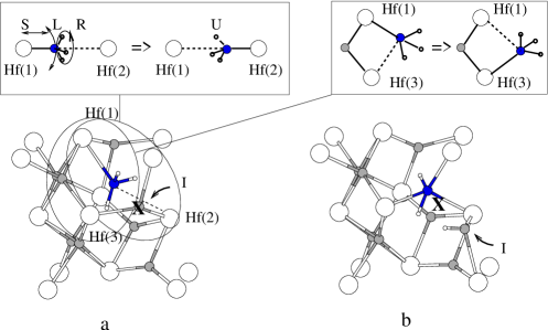
To understand the mechanism of diffusion of ammonia inside the lattice one needs to analyze its vibrations. The molecule’s thermal motion involves primarily four distinct groups of modes: stretching of the Hf(1)–N bond (S), libration of the Hf(1)–N bond (L), rotation of the NH3 around its axis (R), and the ammonia’s so-called ’umbrella’ mode (U) (Figure 6(a)). Two nearly degenerate L-type modes have relatively low frequencies and manifest themselves by large amplitude ’swings’ of the NH3 molecule, in which axis of the molecule remains collinear with the Hf(1)–N bond. These ’swings’ are coupled to the R-type rotations of similar frequencies, so the directions of NH bonds of the molecule may adjust to a local environment. This L-R type thermal motion remains reversible until the C3 axis is aligned with the Hf(1)–Hf(2) direction. Once the Hf(1)-N–Hf(2) bonds are aligned, the S-mode softens, so a swap between the short and long Hf-N bonds becomes possible. As seen in the inset of Figure 6(a), such molecular hops are controlled by S and U vibrations of ammonia and involve only a small nitrogen displacement of under 0.4 Å. The activation energy of the umbrella mode is 0.1 eV (gas phase data Manz et al. (1997)), so frequent NH3 hops between few shallow minima are readely observed in the MD simulations even at T=300K. An alternative mechanism of ammonia hops has transient states between the oxygen bridged Hf atoms (Hf(1) and Hf(3) in Fig. 6(a)). This involves direct S-L type coupling (see inset Fig. 6(a)) and has a higher activation energy. Despite being fairly frequent (at least one event in 1 ps at T=300K), S-U and S-L type hops do not contribute to molecular diffusion, since in such hops the molecule does not leave the original HfO2 interstitial cage.
We have been unable to find a diffusion path for the whole NH3 molecule. In fact, further calculations show that ammonia molecule in the m-HfO2 (Fig. 6(a)) is metastable and dissociates into NH and a proton. The compact (NH-H+) pair is best described as an NH ion replacing an oxygen ion in a 3-coordinated site, while the displaced oxygen traps the proton and relaxes towards the volume interstitial position (Fig. 6(b)). The energy of this configuration is by eV lower than that of the associated molecule. However, the energy barrier between the two configurations is substantially higher than thermal energies. This is reflected by the fact that the molecular NH3 configuration at 300K is stable during the entire MD run (at least 6 ps). However, at T = 600K, which is still below usual PDA temperatures, the dissociation occurs typically within 1-2 ps.
Stability of the dissociated configuration (Fig. 6(b)) is stipulated by the fact that the OH- (or NH) bonds are stretched by the large electrostatic potential gradient near the anion site. Dipole fields of the NH and OH- shearing a single site, mutually counterballance the crystal field effect, and stipulate stronger proton bonds and local neutrality. Consequently, although the initial NH-H+ dissociation between states a and b is exothermic, an infinite separation of H+ and (NH) is endothermic by 0.7 eV (Table 6.1). The latter can be achieved e.g. by proton diffusion away by hopping between the 3-coordinated oxygen ions (Fig. 6(b)). An alternative dissociation path, resulting in the formation of a neutral molecular hydrogen and NH (Table 6.2), is substantially less energetically favorable.
When separated from the proton, the NH radical may change its charge state when an external potential is applied. Our calculations suggest that this molecule can be either positive or negative, whilst the neutral configuration is thermodynamically unstable at any value of EF (Table 2.23). The same applies to hydrogen (2.24), which is only stable as a proton or a negative ion in hafnia (see references Van Der Walle and Neugebauer (2003); Peacock and Robertson (2003) for discussion on hydrogen). Depending on the charge state, the dissociation of NH2 may lead to the formation of a neutral nitrohydrate and a negative or positive hydrogen ion (Table 6.3,4). Both reactions are endothermic by 1.7 and 0.3 eV, respectively. Despite the apparently low dissociation energy, our MD simulations at T = 500 K shows that the NH ion is stable - indicating that the dissociation barrier may be high.
Depending on its charge state, the NH2 molecule binds to the lattice quite differently. The NH ion is iso-electronic to the OH- radical. Therefore, as expected, its most stable configuration is similar to the interstitial OH- centre, as reported for monoclinic zirconia Shluger et al. (2003). NH binds to three Hf ions with a bond length of around 2.3 Å (Fig. 7(a)). In contrast, the NH ion makes an ion-covalent bond with a 3-coordinated oxygen ion (O-N distance 1.4 Å ) and an ionic bond with only one of the cations (N-Hf distance 2.2 Å) (Fig. 7(b)).
Further dissociation of NH2 may lead to the formation of NH species. Calculations predict NH0 to be stable, while NH- is unstable with respect to electron donation to the CB, and NH+ is unstable with respect to proton release (Table 6.6). NH0 molecule forms a dumbell configuration with a 3-coordinated lattice oxygen similar to N interstitial (N–O distance is 1.47 Å ). The equilibrium angle is 107∘, but is soft. Finally, dissociation of NH0 is energetically unfavorable, as discussed previously (Table 6.5).
The presented results suggest that the likely final products of ammonia PDA are NH, NH0 as well as hydrogen. The latter is stable either as a proton or as a negative ion. The detailed dynamical behavior of hydrogen will be discussed elsewhere. NH and NH0 species are unable to trap interstitial oxygen. This agrees with experimental studies showing an increase in interface SiO2 thickness during NH3 PDA. In addition, NH and NH0 (but not NH) can react exothermally with the existing anion vacancies (see Table 4.9,10). The resultant defects create electronic levels near or inside the valence band of hafnia. Therefore, unlike atomic and molecular nitrogen species trapped in oxygen vacancy, NH and NH0 substitutions are stable in only one charge state.
IV Discussion
Our calculations identified the most stable nitrogen containing species and the corresponding energy levels with respect to the band edges of the monoclinic hafnia. It is revealed that most of the stable nitrogen contained products (as well as intrinsic defects) may have multiple charge states depending on the availability of the electrons in the system. In the MOS architecture the main source of electrons in the dielectric is the channel silicon and poly-Si or metallic gate. Therefore, to identify the most likely charge states, the calculated electric levels of defects must be aligned with the silicon bands. Such an alignment is illustrated in Figure 8, where the electric levels are adjusted to the experimental band gap energy as described in the Appendix, and the experimental band off-sets are used for the valence and the conduction bands Afanas’ev et al. (2002); Afanas’ev and Stesmans (2004b). Here we consider main effects caused by these defects.
IV.1 Structural effects
Our calculations predict that all the neutral and negatively charged stable nitrogen species (N2, N, NH, NH0, and H-) incorporate into oxygen vacancies with a substantial energy gain. However, this process is diffusion limited. Since the diffusivity of N2, NH2, NH0, and H- is unlikely to be high, the process of vacancy passivation by molecular nitrogen or ammonia may be incomplete, leaving significantly non-uniform concentrations of interstitials and anion vacancies. In contrast, atomic nitrogen is expected to be rather more mobile resulting in more effective passivation of oxygen vacancies. A similar argument applies to the processes involving anion vacancies in charge states +1 and 0. They are significantly less mobile than the bare V++ due to the electrons localized inside. Consequently, the time to attain thermodynamic equilibrium might be long, and the subtitution by the PDA agent in practical anneals may be incomplete.
IV.2 Electron trap effects
Our calculations put the oxygen vacancy electrical levels into the silicon band gap (Figure 8), which would make them type B defects. However, this attribution is a result of our calculation procedure in which the DFT band gap correction is applied to electron affinities of all defects irrespectively of their origin (see Appendix). Such approximation may become inadequate for the doubly charged oxygen vacancy whose (unoccupied) electronic state splits down from the CBM due to a strong outward displacement of the three nearest neighbour hafnium ions. Thus, a vacancy state originates from a hafnia conduction band, and its electron affinity ought to be calculated accordingly. Assuming that the vacancy level must be shifted up rigidly with CBM, one would obtain relaxed and unrelaxed electrical levels V++/V+ at 0.5 eV and 1.3 eV below CBM. These values give a lower limit for the V++ vertical electron affinity. For the sake of consistency we retain the values obtained by the defect independent procedure outlined in the Appendix, but acknowledge that anion vacancies may belong to a type A, i.e be resonant with the Si CB. Therefore, they may act as shallow traps. Accepting this as a working assumption, the role of nitrogen PDA with regard to the shallow trap problem reduces to the effectiveness of the incorporation of nitrogen species into anion vacancies.
Nitrogen incorporation into the oxygen vacancy sites leads to the lowering of the defect levels, making them less active as electron traps. In this respect, all the considered PDA will reduce the shallow trap concentration, although to a different extent as discussed before.
However, another shallow trap candidate could be a small radius electron polaron in the form of Hf3+ ion, similar to the Zr3+ centres observed in zirconia Ryabchuk (2004). The electron self-trapping if effective, may present a serious problem in the high-k MOSFETs. However, our density functional calculations do not predict this defect as stable, possibly due to the known limitations of local approximations regarding localisation problem Gavartin et al. (2003). Therefore, we leave the problem of small polaron assisted trapping for further investigation.
IV.3 Fixed charge effects
Both N and N2 interstitials and subsitions are deep centres, and according to Figure 8 their relaxed affinities (electrical levels) are all below the VBM of Si, which would make them type C defects. This means that at equilibrium they ought to have maximum negative charge. However, such an equilibrium state assumes that the electrons are supplied from the silicon valence band, which is difficult (if not impossible) for two reasons: 1. The effectiveness of the resonant tunneling strongly depends on the overlap between the states involved in the process. Therefore, defects localized far away from the interface are ineffective electron traps, even if their energy is resonant with Si VB. 2. Charging occurs predominantly via resonant electron tunneling from the Si VB, i.e. it envolves transitions on to the unoccupied defect states. These states (shown as unrelaxed levels in Figure 8) are mostly of type B. Therefore, most of the nitrogen species are unavailable for a resonant tunneling from the silicon valence band. Hence, they may retain multiple non-equilibrium charge states for a very long time, and thus contribute to either positive or negative charge. The possible exceptions are NO interstitials and N substitutions, whose electrical levels are below the Si VBM, so they will quickly achieve maximum negative charge.
The only definite source of positive fixed charge in our calculations are protons and anion vacancies. With regard to these defects, atomic nitrogen and molecular nitrogen will reduce vacancy concentration, but may themselves produce negative or positive charge states as disscussed above. Ammonia anneal will result in higher concentration of protons, but it is unclear how much of these will be evacuated during the anneal, so the increase in positive charge is expected with the NH3 PDA.
Finally, we would like to emphasise that high-k materials generally favour charged defect states, due to their large polarization energy. This is quantified for m-HfO2 in Table 2.
We conclude that nitrogen’s capacity for reducing fixed charge in hafnium oxide is limited. Therefore, the problem of fixed charge built up and VT instability is not resolved by PDA. Hinkle and Lukowsky Hinkle and Lukovsky (2003) reported that bulk only nitridation does not decrease and may even increase fixed charge in the oxide film, which is in qualitative agreement with our calculations.
IV.4 Growth of the interfacial SiOx layer
We assume that growth of the SiOx layer at the interface is controlled by a migration of oxygen towards the interface. Therefore, we considered how various PDA gases interact with oxygen interstitials. Our calculations predict N2 does not bond to oxygen interstitial in any charge state (Table 3). Therefore, interstitial oxygen is free to diffuse towards the interface. In contrast, atomic N strongly bonds to the interstitial oxygen, forming less mobile NO- molecules. As a result oxygen diffusion towards the interface is blocked, thus inhibiting growth of interfacial SiOx layer. This conclusion is consistent with data on nitrogen remote plasma deposition processing Hinkle and Lukovsky (2003), where reduction of interfacial silica growth has been observed.
Ammonia molecules in m-HfO2 dissociate spontaneously resulting in the formation of NH, NH0, H+ and possibly H2 and H-. Of these products, only protons will effectively bond to the interstitial oxygen ions and exclusively to those in the charge state -2. At the same time, the most mobile charge state of oxygen, O-Foster et al. (2002b), does not interact strongly with protons. Therefore, ammonia PDA will not inhibit effectively the growth of the interfacial SiOx layer. The same applies to the PDA with nitric oxide.
IV.5 Perspective and future work
Our calculations suggest that hafnium oxynitride might have better properties as a gate oxide. Due to the multiplicity of the NO oxidation states, this material may form stable amorphous structures with acceptable dielectric properties. Some preliminary results on hafnium oxynitride gates in MOSFET have been recently reported Choi et al. (2003); Kang et al. (2002), but a more systematic study of film composition and electrical properties is required.
In this work we have considered only bulk structures close to their thermodynamic equilibrium. There exists strong experimental evidence Hinkle and Lukovsky (2003); Afanas’ev and Stesmans (2004a) that in certain cases a significant part of the electron traps are located in the bulk of the insulator. However, fixed charge distant from the channel is well screened and therefore, has only limited effect on the channel mobility. So, to understand the processes in the channel, an extension of this work is required towards systems which include interface effects - work in this direction is currently under way. Also, we note that bulk DFT calculations only give an indication of the defect charge states that are thermodynamically possible. Some of these states may or may not be relevant depending on the values of the electron chemical potential. Moreover, charge transport through the dielectric is generally slow, so actual defect states may be controlled kinetically rather than thermodynamically. Additionally, calculations of relative energies of defects in different charge states require empirical corrections due to various limitations of the method applied (e.g ill-defined zero energy and spurious electrostatic interactions in periodic boundary conditions, underestimation of the energy band gap etc.). Such corrections must be treated with some caution, and new theoretical developments are required for a more rigorous approach.
Acknowledgements.
The funding of the EU Framework 5 HIKE project is gratefully acknowledged. This research has been supported in part by the Academy of Finland through its Centre of Excellence Program (2000-2005). The calculations were performed on resources provided by the HyperSpace supercomputer Center at University College London, HPCX UK (Materials Chemistry Consortium) and the Centre of Scientific Computing, Espoo, Finland. We are grateful to A. M. Stoneham, V. Afanasiev, A. Asenov and A. Korkin for useful discussions.Appendix A Calculation of Formation and Ionization Energies, and Electron and Hole Affinities
The formation energy of a defect in the charge state is given by:
| (1) |
where denotes the total energy calculated for the system at the equilibrium geometry and the excess supercell charge in units of the electron charge , is the energy of the perfect HfO2 crystal in the charge state , is the energy of the isolated molecule, and all energies are calculated in the same supercell. Depending on the value of , the thermodynamically stable charge state of the specific defect may change.
In order to study stable charged defect states and the possible role of defects in photo- and thermo-stimulated processes, as well as in electronic devices one needs to know the electron affinities and ionization energies of the defect states with respect to the bottom of the conduction band of hafnia and to other electron or hole sources, such as silicon.To achieve that, we compare total energies of the initial and final systems with the same number of electrons. The main inaccuracy of this approach is related to the underestimation of the band-gap in the DFT calculations. This means that the defect states appear to be closer to the valence band and conduction band edges in hafnia. The relative error in the energy level position with respect to the gap edges depends on a defect and is impossible to establish without proper calibration using experimental data.
Defining the absolute value of the defect ionization energy as the vertical excitation energy of an electron from the defect with the charge to the bottom of the conduction band, we have:
| (2) |
where the value is calculated for the geometry of the relaxed defect with charge and is a correction for the position of the bottom of the conduction band. Similarly we can define the electron affinity of the defect (i.e. the energy gain when the electron from the bottom of the conduction band is trapped at the defect) as follows:
| (3) |
Here the correction can be generally different from One can consider both “vertical” and “relaxed” electron affinities. In the latter case the lattice relaxation after the electron trapping is included in . We can also define the hole affinity of the defect , i.e. the energy gain when the a free hole is trapped from the top of the valence band to the defect as follows:
| (4) |
Again, dependent on whether the lattice relaxation in the final state is included or not, one will obtain different affinities. The vertical hole affinity provides a useful estimate of the position of the defect state with respect to the top of the valence band. One can also verify, that the relaxed affinity is related to the defect’s q+1/q electric level as defined elsewhere (e.g. Ref. Van de Walle (2004)).
To define the corrections , we use the following considerations. i) We assume that the main inaccuracy in defining the relative positions of defect states with respect to the band-gap edges is due to unoccupied Kohn-Sham states, and that the underestimated band gap is mainly due to the too low position of the conduction band minimum. Therefore, we use an approximation that = = and = 0. These conditions are difficult to fully justify without comparison with experiment. ii) Using these conditions and definitions (3) and (4) it is easy to obtain:
| (5) |
where both affinities correspond to relaxed final defect states. This condition holds in all calculations, which insures the consistency of our approach. iii) We use the experimental value of eV Balog et al. (1977) to define the difference
| (6) |
and correct the defect ionization potentials and electron affinities. This gives eV, which is used in all calculations.
Although this method is approximate, fixing the value of allows us to present the results of our calculations in one scale. Another advantage is that, in order to find defect affinities with respect to electrons at the bottom of silicon conduction band or holes at the top of silicon valence band, within the same method one can use the experimental value of band offset with Si. This scale can be changed if a more "accurate" or relevant value for will be found. This will require only a shift of our predicted values by a constant.
References
- Kingon et al. (2000) A. I. Kingon, J. P. Maria, and S. K. Streiffer, Nature 406, 1032 (2000).
- Huff et al. (2003) H. R. Huff, A. Hou, C. Lim, Y. Kim, J. Barnett, G. Bersuker, G. A. Brown, C. D. Young, P. M. Zeitzoff, J. Gutt, et al., Microelectronic Eng. 2–4, 152 (2003).
- Chau et al. (2003) R. Chau, S. Datta, M. Doczy, J. Kabalieros, and M. Metz, in International Workshop on Gate Insulator 2003 (IWGI) (2003).
- Wilk et al. (2001) G. Wilk, R. Wallace, and J. Anthony, J. Appl. Phys. 89, 5243 (2001).
- Wong (2002) H. S. P. Wong, IBM. J. Res. & Dev. 46, 133 (2002).
- Young et al. (2004) C. D. Young, G. Bersuker, G. A. Brown, P. Lysaght, P. Zeitzoff, R. W. Murto, and H. R. Huff, in IEEE Internationasl Reliability Physics Symposium (Phoenix, AZ, 2004), pp. 597–598.
- Young et al. (2003) C. D. Young, A. Kerber, T. H. How, E. Cartier, G. A. Brown, G. Bersuker, Y. Kim, C. Lim, J. Gutt, P. Lysaght, et al., in The Electrochemical Society Proceedings Series (Pennington, NJ, 2003), vol. PV 2003-22, pp. 347–362.
- Kerber et al. (2003) A. Kerber, E. Cartier, L. Pantisano, R. Degraeve, T. Kauerauf, Y. Kim, A. Hou, G. Groeseneken, H. E. Maes, and S. U., IEEE Electron Dev. Lett. 24, 87 (2003).
- Carter et al. (2003) R. J. Carter, E. Cartier, A. Kerber, L. Pantisano, T. Schram, S. De Gendt, and M. Heyns, Appl. Phys. Lett. 83, 533 (2003).
- Bersuker et al. (2004a) G. Bersuker, P. Zeitzoff, G. Brown, and H. R. Huff, Materials Today p. 26 (2004a).
- Stesmans and Afanas’ev (2004) A. Stesmans and V. V. Afanas’ev, in High-k Dielectrics, edited by M. Houssa (IOP Publishing, Bristol and Philadelphia, 2004), pp. 190–216.
- Afanas’ev and Stesmans (2002) V. Afanas’ev and A. Stesmans, Appl. Phys. Lett. 80, 1261 (2002).
- Houssa et al. (2002) M. Houssa, J. L. Autran, V. V. Afanas’ev, A. Stesmans, and M. M. Heyns, J. Electrochem. Soc. 149, F181 (2002).
- Foster et al. (2002a) A. S. Foster, F. Lopez Gejo, A. L. Shluger, and R. M. Nieminen, Phys. Rev B 65, 174117 (2002a).
- Foster et al. (2002b) A. S. Foster, A. L. Shluger, and R. M. Nieminen, Phys. Rev. Lett. 89, 225901 (2002b).
- Shluger et al. (2003) A. L. Shluger, A. S. Foster, J. L. Gavartin, and P. V. Sushko, in In Nano and Giga Challenges in Microelectronics., edited by J. Greer, A. Korkin, and J. Labanowski (Elsevier, 2003), pp. 151–222.
- Bersuker et al. (2004b) G. Bersuker, J. Barnett, N. Moumen, B. Y. C. D. Foran, P. Lysaght, J. Peterson, B. H. Lee, P. M. Zeitzoff, and H. R. Huff, Jap. J. Appl. Phys p. in press (2004b).
- Hinkle and Lukovsky (2003) C. Hinkle and J. Lukovsky, Appl. Surf. Sci. 216, 124 (2003).
- Afanas’ev and Stesmans (2004a) V. V. Afanas’ev and A. Stesmans, J. Appl. Phys. 95, 2518 (2004a).
- Afanas’ev and Stesmans (2004b) V. V. Afanas’ev and A. Stesmans, in High-k Dielectrics, edited by M. Houssa (IOP Publishing, Bristol and Philadelphia, 2004b), pp. 217–250.
- Stemmer and Schlom (2003) S. Stemmer and D. G. Schlom, in In Nano and Giga Challenges in Microelectronics., edited by J. Greer, A. Korkin, and J. Labanowski (Elsevier, 2003), pp. 129–150.
- Opila and Eng Jr (2002) R. L. Opila and J. Eng Jr, Prog. Surf. Sci. 69, 125 (2002).
- Balog et al. (1977) M. Balog, M. Schieber, M. Michiman, and S. Patai, Thin Solid Films 41, 247 (1977).
- Aarik et al. (2000) J. Aarik, A. Aidla, H. Mändar, V. Sammelsberg, and T. Uuustare, J. Cryst. Growth 220, 105 (2000).
- Neumayer and Cartier (2001) D. A. Neumayer and E. Cartier, J. Appl. Phys 90, 1801 (2001).
- Afanas’ev et al. (2002) V. V. Afanas’ev, A. Stesmans, F. Chen, X. Shi, and S. A. Campbell, Appl. Phys. Lett. 81, 1053 (2002).
- Kresse and Furthmüller (1996a) G. Kresse and J. Furthmüller, Comp. Mat. Sci. 6, 15 (1996a).
- Kresse and Furthmüller (1996b) G. Kresse and J. Furthmüller, Phys. Rev. B 54, 11169 (1996b).
- Perdew et al. (1992) J. P. Perdew, J. A. Chevary, S. H. Vosko, K. A. Jackson, M. R. Pederson, D. J. Singh, and C. Fiolhais, Phys. Rev. B 46, 6671 (1992).
- Vanderbilt (1990) D. Vanderbilt, Phys. Rev. B 41, 7892 (1990).
- Kresse and Hafner (1994) G. Kresse and J. Hafner, J. Phys.: Condens. Matter 6, 8245 (1994).
- Ruh and Corfield (1970) R. Ruh and P. W. R. Corfield, J. Amer. Ceram. Soc. 53, 126 (1970).
- Adams et al. (1991) D. M. Adams, S. Leonard, D. R. Russel, and R. J. Cernik, J. Phys. Chem. Solids 52, 1181 (1991).
- Leslie and Gillan (1985) M. Leslie and M. J. Gillan, J. Phys. C: Solid State Phys. 18, 973 (1985).
- Kantorovich (1999) L. N. Kantorovich, Phys. Rev. B 60, 15476 (1999).
- Kutzler and Painter (1988) F. W. Kutzler and G. S. Painter, Phys. Rev. B 37, 2850 (1988).
- Szymanski et al. (2001) M. A. Szymanski, A. L. Shluger, and A. M. Stoneham, Phys. Rev. B 63, 224207 (2001).
- Crocombette (1999) J. P. Crocombette, Phys. Chem. Minerals 27, 138 (1999).
- Foster et al. (2001) A. S. Foster, V. B. Sulimov, F. L. Gejo, A. L. Shluger, and R. M. Nieminen, Phys. Rev. B 64, 224108 (2001).
- Foster et al. (2002c) A. S. Foster, V. B. Sulimov, F. L. Gejo, A. L. Shluger, and R. M. Nieminen, J. Non-Cryst. Solids 303, 101 (2002c).
- Manz et al. (1997) J. Manz, P. Saalfrank, and B. Schmidt, J. Chem. Farady Trans. 93, 957 (1997), roto-vibrationally mediated chemistry of NH3 is discussed + umpbrella mode.
- Van Der Walle and Neugebauer (2003) C. G. Van Der Walle and J. Neugebauer, Nature 423, 626 (2003).
- Peacock and Robertson (2003) P. W. Peacock and J. Robertson, Appl. Phys. Lett. 83, 2025 (2003).
- Ryabchuk (2004) V. Ryabchuk, Int. J. Photoenergy 6, 95 (2004).
- Gavartin et al. (2003) J. L. Gavartin, P. V. Sushko, and A. L. Shluger, Phys. Rev. B 67, 035108 (2003).
- Choi et al. (2003) C. H. Choi, T. S. Jeon, R. Clark, and D. Kwong, IEEE Electron Device Lett. 24, 215 (2003).
- Kang et al. (2002) C. S. Kang, H.-J. Cho, K. Onishi, R. Nieh, R. Choni, S. Gopalan, S. Krishnan, J. H. Han, and J. C. Lee, Appl. Phys. Lett. 81, 2593 (2002).
- Van de Walle (2004) C. G. Van de Walle, J. Appl. Phys 95, 3851 (2004).