ESR spectrometer with a loop-gap resonator for cw and time resolved studies in a superconducting magnet
Abstract
The design and performance of an electron spin resonance spectrometer operating at 3 and 9 GHz microwave frequencies combined with a 9 T superconducting magnet is described. The probehead contains a compact two-loop, one gap resonator and is embedded in the variable temperature insert of the magnet enabling measurements in the 0- 9 T magnetic field and 1.5-400 K temperature range. The spectrometer allows studies on systems where resonance occurs at fields far above the paramagnetic condition such as in strongly interacting spin systems. The low quality factor of the resonator allows time resolved experiments such as e.g. longitudinally detected ESR. We demonstrate the performance of the spectrometer on the MgB2 superconductor and the RbC60 conducting alkaline fulleride polymer.
INTRODUCTION
Recent developments in electron spin resonance instrumentation aims at the use of high microwave frequencies and magnetic fields. This allows to obtain higher resolution and the study of magnetic field and microwave frequency dependent phenomena eatonreview ; freedsum ; hassan . Most spectrometers utilize a superconducting magnet with a resonant structure built in the bore providing high sensitivity, such as Fabry-Pérot nijmegen ; freedreson ; smith or cylindrical cavity resonators schmidt ; hill . An alternative is to use the superconducting magnet in combination with a simple pass configuration that enables temperature variability and multi-frequency operation at the cost of sensitivity nh3k3c60 ; mgb2 . Although, HF-ESR is seen to gain growing importance, the conventional low-field ESR experiments, such as X-band, are usually required to complement the spectroscopic information. It is often desired to perform the low frequency experiments under similar experimental conditions than those at the high frequencies e.g. at low temperatures (down to 1.5 K) that is usually not available in commercial X-band spectrometers. A yet unexplored domain of the frequency-field diagram is the use of low microwave frequencies ( 10 GHz) combined with high magnetic fields (6 T or higher). This would enable to obtain extra information on strongly correlated spin systems e.g. antiferromagnets. The primary obstacle for the development of such spectrometers is the small usable size for a resonant microwave structure required for measurements in superconducting magnet bores. The recent developments of the NMR instrumentation beyond 1 GHz enters the same domain with the same difficulties. A solution which satisfies all these requirements would be an X-band spectrometer combined with a superconducting magnet.
Here, we describe the development and performance of an ESR spectrometer that allows the use of low frequencies in the S (2-4 GHz) and X (8-12 GHz) bands and high magnetic fields (up to 9 T). A loop-gap resonator (LGR) with coaxial leads is embedded in the variable temperature insert of a superconducting magnet that is also used for high field/frequency ESR measurements with a simple pass probehead. The LGR design is advantageous when lower cavity quality and higher sample filling factors are required such as for time resolved experiments for these microwave bands Froncisz ; FronciszRSI ; SchweigerRSI ; MobiusRSI1997 ; MobiusRSI1998 . The instrument has two orders of magnitude lower sensitivity than a commercial ESP300 Bruker spectrometer that is compensated by the 20 times larger usable samples providing comparable signal when sufficient sample amounts are available. The apparatus has comparable sensitivity as the simple pass HF-ESR spectrometer and allows studies on the same samples. The special design of the LGR provides transparency for rf radiation ( 10 MHz) and allows longitudinally detected ESR (LOD-ESR) measurements at S and X bands. LOD-ESR complements continuous wave (cw) ESR and spin-echo methods as it allows the measurement of short longitudinal relaxation times pescia ; strutz ; atsarkin ; MuranyiJMR and to separate overlapping ESR signals of spin species schweigerAMR ; schweigerJMR ; ablart ; martinelli . The instrument detects the modulation of the longitudinal magnetization, , induced by a chopped microwave field, using a pick-up coil parallel to the external magnetic field, . LOD-ESR spectrometers were previously built at X-band and we recently reported the development of the high field version MuranyiJMR . The performance of the apparatus in the cw-ESR mode is demonstrated on the MgB2 superconductor below and in the LOD-ESR mode on the RbC60 conducting alkaline fulleride polymer.
THE SPECTROMETER
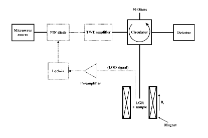
The block-diagram of the spectrometer operating in the cw-ESR mode including the optional LOD-ESR elements (dashed) is shown in Figure 1. The microwave bridge is made of commercially available coaxial elements. The coaxial microwave circuit is connected to the probehead with a flexible coaxial cable (Pasternack Enterprises, PE3481) providing sufficient mechanical stability. The source is an Agilent (Agilent 83751B) synthesized frequency sweeper (2-20 GHz, maximal output power 20 dBm) that is locked to the microwave resonator (see below). The microwaves are directed toward the sample with a 4 port circulator (DITOM D4C2040 for 2-4 GHz and D4C8012 for 8-12 GHz) whose fourth port is terminated with a precision 50 Ohm (Pasternack, PE6071). The microwave loss is 1 dB for the 2-4 GHz band and 3 dB at 8-12 GHz for the exciting and the reflected signals. The broad-band microwave detector (Agilent 8474C, 0.01-33 GHz, sensitivity 500 mV/mW) does not require microwave bias thus we do not employ a reference microwave arm. Magnetic field modulation is driven by a lock-in (Stanford Research Systems SRS830, 1 mHz-102 kHz) through a home-built U/I converter.
The instrumentation of the LOD-ESR experiments closely follows the previous design of the HF-LOD-ESR apparatus MuranyiJMR and here is only outlined. A coaxial PIN diode (Advanced Technical Materials, S1517D, 0.5-18 GHz bandwidth, switching speed: 10-90 %, 90-10 %: 10 ns, insertion loss: 3 dB at 3 GHz and 5 dB at 9 GHz) provides the rapid microwave amplitude modulation and at X-band a TWT microwave amplifier (Varian, TWTA VZX-6980GZ, 8-12.4 GHz, maximum output 40 dBm, amplification 40 dB) is also built in. The PIN diode is driven by a high frequency lock-in (Stanford Research Systems, SRS844, 0.025-200 MHz). An rf parasite component with the modulation frequency appearing on the output of the PIN diode is suppressed out with a band-pass microwave filter consisting of two facing waveguide to coaxial adapters (Agilent X281A). The LOD-ESR signal is detected with a longitudinal coil (see also below) that is part of an rf LC circuit. The capacitors are placed outside the magnet to prevent temperature drift of the rf resonance frequency. The LOD signal is amplified through a low noise rf preamplifier (Analog Modules 322-6-50, 200 Hz-100 MHz, gain 40 dB, input noise 380 pV/) and is phase sensitively detected by the SRS844 lock-in.
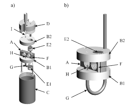
The spectrometer is based on a high homogeneity (10 ppm/cm) superconducting magnet (Oxford Instruments, 0-9 T) that is equipped with a variable temperature insert (VTI) for the 1.5-400 K temperature range and is regularly used for cw-HF-ESR measurements. Exchange gas in the sample compartment (40 mm internal diameter) thermally connects it to the VTI. Separation of the He gas in the sample compartment and the VTI avoids rapid He pressure changes inside the resonator when the cooling rate is modified. The outline of the probehead is shown in Figure 2. Its outer diameter is 38 mm. Except the LGR itself, all elements are made of brass (CuZn39Pb3). The LGR (A) is placed between a lower (B1) and an upper (B2) microwave shield which are surrounded by an on-screwable shielding cap (C). These are fixed to the upper support (D) that is connected to the top of the magnet with two stainless steel tubes (not shown). Heating resistance is also attached to the upper support, the thermometer (Lakeshore, Cernox CX1050-SD) fixed to the LGR provides precise temperature monitoring of the sample. In cw-ESR mode, two coils (E1, E2) in an almost optimal Helmholtz configuration provide modulation with 0.6 mT/A. The coils are connected with a cable that is embedded in a brass tube (F) to prevent microphonics. The upper coil is connected to a semi-rigid coaxial cable above the D support with a short section of shielded flexible coaxial cable (not shown). We also use a pair of coils to detect the LOD rf signal in a quasi-Helmholtz configuration (see below). The shielded cabling guarantees shielding from the noisy environment, which is crucial for the LOD-ESR studies MuranyiJMR .
The microwaves are directed to the sample with a semi-rigid coaxial cable (Pasternack, PE3931) that is connected to a curved coaxial cable section (G) and ends in a capacitive antenna (H). Coupling is varied by a movable grounded screw (I) that is uniaxial with the antenna following Ref. MobiusRSI1998 . The capacitive coupling is of smaller size and provides enhanced mechanical stability as compared to the inductive one MobiusRSI1998 . The fine adjustment of the coupling is performed by moving the coupling screw towards the antenna. On approaching the antenna, the coupling increases. However, the coupling screw is only 3.8 mm apart from the LGR and its movement affects the resonance frequency. To minimize the required movement of the screw, the cavity is slightly undercoupled by adjusting the effective length of the antenna before inserting the probehead into the magnet.
The synthesized sweeper enables a simple design of the automatic frequency control (AFC) as it allows the frequency control through a DC feed-back signal and also AC modulation. Thus the AFC involves an analogue lock-in (Stanford Research Systems SRS510) together with a simple circuit with passive elements only.
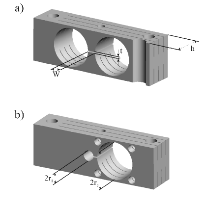
The LGRs for the different experiments are shown in Fig. 3. Fig. 3a. and b. show the resonators used for cw-ESR measurements at 3 GHz and for LOD-ESR measurements at 9 GHz, respectively. Similar LGRs were constructed for the 3 GHz LOD-ESR and 9 GHz cw-ESR (not shown). The dimensions of the LGRs together with the calculated and measured resonance frequencies and quality factors are summarized in Table I. The LGR parameter notations are taken from Ref. FronciszRSI and are shown in Fig. 3. The calculated resonance frequency, , is obtained from the equivalent LC circuit using Eq. 2. in Ref. FronciszRSI and the resonant frequency with finite size corrections, is calculated from Eq. 16 in Ref. FronciszRSI . The small space available for closing the flux inside the brass cap gives rise to a further 10 % frequency up-shift. The design allows the use of cylindrically shaped samples with diameters up to 8 mm and a height of 5 to 8 mm that are used for the simple pass HF-ESR apparatus with 8 mm stainless steel tubing, such as a loose powder contained in a Teflon sample holder of a metallic sample as RbC60 JanossyPRL or fine grains of MgB2 cast in epoxy mgb2 .
| LGR | Q(copper) | Q(brass) | ||||||||
|---|---|---|---|---|---|---|---|---|---|---|
| 3 GHz | 4.5 | 4.5 | 2 | 0.3 | 8 | 3.26 | 3.25 | 3.55 | 500 | - |
| 9 GHz | 4.5 | 1.5 | 1 | 0.3 | 8 | 8.41 | 8.33 | 8.99 | 350 | 250 |
The thin upper and lower walls of the LGR and the cuts perpendicular to the axis of the loops minimize eddy currents in the field modulation detected cw-ESR experiments. For LOD-ESR measurements, we use cavities made of the lower conducting brass to obtain better transparency for the detected rf signal. The pick-up coil is wound through the holes indicated in Fig. 3b. in a quasi-Helmholtz configuration providing good transparency for the rf signal. The interaction between microwaves and the pick-up coil does not affect the pick-up signal. In the LOD-ESR mode, we have 12 dBm at 9 GHz and 16 dBm at 3 GHz at the sample. At 9 GHz, we can use a TWT amplifier (see Fig. 1) for the LOD-ESR measurements. The 4 port circulator limits the maximum power to 36 dBm peak or 33 dBm cw power. At low temperatures the power is limited to lower values.
PERFORMANCE OF THE SPECTROMETER
The cw-ESR spectrometer
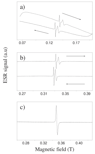
In Fig. 4, we show typical cw-ESR spectra of MgB2 in the superconducting state of this material. MgB2 is a highly conducting material in its normal state and becomes a superconductor below = 39 K akimitsu . The spectra were measured by the currently described spectrometer (a and b) at S and X-band, respectively, as well as on a Bruker ESP300 commercial spectrometer at X-band (c). In the fine powder of the MgB2 superconductor the conducting particles were separated by a powder of the non-magnetic SnO2 insulator mgb2 ; Simoncondmat . Measurement in the superconducting magnet requires a magnetic field calibrating -factor standard. We used KC60 that has a narrow line with a temperature independent intensity and -factor. Spectra of comparable quality can be obtained with the current LGR and the commercial spectrometers. The calculated sensitivity of the current spectrometer is 21013 spin/G and 51012 spin/G at for the S and X band LGRs, respectively. These values have to be compared to the 51010 spin/G of the ESP300 spectrometer determined on the same samples. The lower sensitivity can be partially compensated by the possibility of using up to 20 times larger amounts of the same sample without affecting the resonance mode of the cavity. As a result, we found that the current spectrometer provides only a factor 3-4 times smaller signal to noise ratios than the commercial apparatus when there is no limit on the sample availability. The sensitivity of the LGRs is comparable to that of the simple pass HF-ESR apparatus 1013 spin/G at 75 GHz Janossyunpublished .
An advantage of the lower of the LGR is that it allows the detection of ESR in superconductors in magnetic fields as low as 0.1 T as Fig. 4a demonstrates. The so-called vortex noise has been a limiting factor of field modulated ESR studies in superconductors using high commercial cavities that could be overcome only by avoiding magnetic field modulation JanossyPhysC . Detailed temperature dependent study of MgB2 have been published separately Simoncondmat .
The LOD-ESR spectrometer
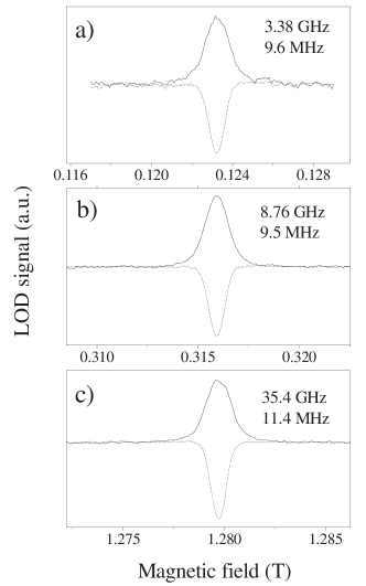
In Fig. 5, we compare the performance of our spectrometer operating in the LOD mode with the previously developed 35 GHz simple pass LOD-ESR apparatus MuranyiJMR . We used RbC60 to calibrate and test the performance of our system. The LOD-ESR signal is proportional to the ESR saturation factor, , where , , and are the electron gyromagnetic factor, exciting microwave field, longitudinal and transversal relaxation times, respectively. Compared to the simple pass () 35 and 75 GHz LOD-ESR spectrometers, a -fold increase in the signal is expected in the current spectrometer. The use of smaller magnetic fields reduces the longitudinal magnetization and the corresponding LOD signal. Altogether, one order of magnitude better performance is expected at the same power than with the 35 GHz spectrometer. However, we observed experimentally that the signal amplitudes are similar. The probable origin of the 10 times smaller sensitivity than expected is that the coil and microwave filling factors are smaller than for the 35 GHz LOD-ESR spectrometer. The quasi-Helmholtz configuration for the pick-up coils is known to have HoultJMR a smaller filling factor than the solenoid used at 35 GHz MuranyiJMR . The magnetic component of the microwave field inside the cavity is highly inhomogeneous and a substantial part of the sample is not in the maximum field position. This yields an experimentally determined 71016 spin/G3/2 at 3.5 GHz (16 dBm) and 1.51016 spin/G3/2 at 9 GHz (at 12 dBm), this has to be compared to the 35 GHz simple pass LOD ESR that had 3.31016 spin/G3/2 at 12 dBm MuranyiJMR . At 9 GHz the TWT power amplifier at 33 dBm output power allows to achieve a maximum sensitivity of 1.51014 spin/G3/2.
RbC60 has relaxation times in the 13-46 ns range that cannot be measured with usual spin-echo methods. On the other hand, LOD-ESR has been successful in determining in this compound atsarkin ; MuranyiJMR . The full method of obtaining data from the raw LOD-ESR data was reported previously MuranyiJMR and is only outlined here. In the simplest case pescia ; atsarkin when , the ratio of the in () and out-of phase () components of the oscillating longitudinal magnetization gives: . The accuracy of measuring relies not only on the magnitude of the detected LOD-ESR signal but also on the microwave amplitude modulation frequency, this latter being optimal when . The maximum modulation frequency of our apparatus is limited to 10 MHz by the bandwidth of the LGRs used and the switching speed of the PIN diode. The best accuracy is for of 16 ns. However, ’s down to 5 ns can still be measured with reduced accuracy.
CONCLUSION
In conclusion, we presented the construction and the performance of a spectrometer that utilizes low microwave frequencies and is embedded in the VTI of a superconducting magnet. The spectrometer is made of commercially available elements and its performance is comparable to the commercially available resistive magnet based S and X-band spectrometers. Thus, our system is an affordable alternative to the commercial low-frequency spectrometers and it can be readily installed at an HF-ESR laboratory. In addition, the system allows time resolved ESR experiments such as the detection of longitudinally detected ESR thus allowing the measurement of very short ’s in metallic samples. The current spectrometer completes the previously developed 35 GHz version of LOD-ESR enabling magnetic field dependent relaxation studies. We plan to perform experiments on systems where combination of low frequencies and high magnetic fields is required such as in antiferromagnets nanio2 . The approach reported here may also find applications in the emerging ultra-high field NMR applications as customary NMR frequencies approach the 1 GHz value clark where our resonator design, completed with frequency tunability appears to be a feasible design.
ACKNOWLEDGEMENTS
This work is dedicated to the memory of László Berende. The authors would like to express their gratitude to A. Jánossy for helping the development of the current spectrometer and for many useful discussions. L. Forró is acknowledged for providing the RbC60 sample and for allowing the use of the ESP300 spectrometer. C. Petrovic, S. Bud’ko, and P. Canfield are acknowledged for the MgB2 sample. A. Sienkiewicz is gratefully acknowledged for suggesting the design of the resonator. B. Horváth is acknowledged for the technical assistance. Support from the Hungarian State Grants, OTKA T043255, OTKA TS040878, OTKA NDF45172 and FKFP 0352/1997 are acknowledged. FS acknowledges the Bolyai Hungarian Research Fellowship and the PATONN Marie-Curie MEIF-CT-2003-501099 grants for support and the hospitality of the University of Vienna during the preparation of the manuscript.
∗corresponding author: simon@esr1.fkf.bme.hu
†Current address: Institut für Materialphysik, Universität Wien, Strudlhofgasse 4, A-1090, Wien, Austria
REFERENCES
References
- (1) G. R. Eaton and S. S. Eaton, App. Magn. Res. 16 (1999) 159.
- (2) J. H. Freed, Ann. Rev. Phys. Chem. 51 (2000) 655.
- (3) A. K. Hassan, L. A. Pardi, J. Krzystek, A. Sienkiewicz, P. Goy, M. Rohrer, and L. C. Brunel, J. Magn. Res. 142 (2000) 300.
- (4) E. J. Reijerse, P. J. van Dam, A. A. K. Klaassen, W. R. Hagen, P. J. M. van Bentum, and G. M. Smith, App. Magn. Res. 14 (1998) 153.
- (5) J. P. Barnes, J. H. Freed, Rev. Sci. Instrum. 69 (1998) 3022.
- (6) G. M. Smith, J. C. G. Lesurf, R. H. Mitchell, and P. C. Riedi, Rev. Sci. Instrum. 69 (1998) 3924.
- (7) J. A. J. M. Disselhorst, H. van der Meer, O. G. Poluektov, and J. Schmidt, J. Magn. Reson. 116 (1995) 183.
- (8) S. Hill, N. S. Dalal, and J. S. Brooks, App. Magn. Res. 16 (1999) 237.
- (9) F. Simon, A. Jánossy, F. Murányi, T. Fehér, H. Shimoda, y. Iwasa, G. Baumgartner, and L. Forró, Phys. Rev. B 61 (2000) 3826.
- (10) F. Simon, A. Jánossy, T. Fehér, F. Murányi, S. Garaj, L. Forró, C. Petrovic, S. L. Bud’ko, G. Lapertot, V. G. Kogan, and P. C. Canfield , Phys. Rev. Lett. 87 (2001) 047002.
- (11) W.Froncisz and J. S. Hyde, J. Magn. Reson. 47 (1982) 515.
- (12) W.Froncisz, T. Oles, and J. S. Hyde, Rev. Sci. Instrum. 57 (1986) 1095.
- (13) M. Willer, J. Forrer, J. Keller, S. Van Doorslaer, A. Schweiger, R. Schuhmann, and Th. Weiland, Rev. Sci. Instrum. 71 (2000) 2807.
- (14) V.Weis, W. Mittelbach, J. Claus, K. Möbius,and T. Prisner, Rev. Sci.Instrum. 68 (1997) 1980.
- (15) G. Elger,J. T. Törring, K. Möbius, Rev. Sci.Instrum. 69 (1998) 3637.
- (16) J. Pescia, Ann. Phys. 10 (1965) 389.
- (17) T. Strutz, A. M. Witowski, R. E. M. de Hekker, and P. Wyder, Appl. Phys. Lett. 57 (1990) 831.
- (18) V. A. Atsarkin, V. V. Demidov, and G. A. Vasneva, Phys. Rev. B 52 (1995) 1290.
- (19) F. Mur nyi, F. Simon, F. Fülöp, A. J nossy, J. Magn. Res. 167 (2004) 221.
- (20) J. Granwehr and A. Schweiger, Appl. Magn. Res. 20 (2001) 137.
- (21) J. Granwehr, J. Forrer, A. Schweiger, J. Magn. Res. 151 (2001) 78.
- (22) G. Ablart, J. Pescia, S. Clement, and J. P. Renard, Solid State Comm. 45 (1983) 1027.
- (23) M. Martinelli, L. Pardi, C. Pinzini, and S. Santucci, Solid State Comm. 17 (1975) 211.
- (24) A. Jánossy, N. Nemes, T. Fehér, G. Oszlányi, G. Baumgartner, and L. Forró, Phys. Rev. Lett. 79 (1997) 2718.
- (25) J. Nagamatsu, N. Nakagawa, T. Muranaka, Y. Zenitani, and J. Akimitsu, Nature, 410 (2001) 63.
- (26) F. Simon, A. Jánossy, T. Fehér, F. Murányi, S. Garaj, L. Forró, C. Petrovic, S. L. Bud’ko, R. A. Ribeiro and P. C. Canfield cond-mat/0302620.
- (27) A. Jánossy and R. Chicault, Physica C 192 (1992) 399.
- (28) A. Jánossy et al. unpublished.
- (29) D. I. Hoult and R. E. Richards, J. Magn. Res. 24 (1976) 71.
- (30) E. Chappel, M.D. Nunez-Regueiro, F. Dupont, G. Chouteau, C. Darie, and A. Sulpice, Eur. Phys. J. B 17 (2000) 609.
- (31) W. G. Clark, P. Vonlanthen, A. Goto, K. B. Tanaka, B. Alavi, W. G. Moulton, A. Reyes, and P. Kuhns, Int. J. Mod. Phys. 16 (2002) 3252.