Voltage Dependence of Spin Polarized Tunneling
Abstract
A mesoscopic spin valve is used to determine the effective spin polarization of electrons tunneling from and into ferromagnetic transition metals at finite voltages. The tunneling spin polarization from the ferromagnet (FM) slowly decreases with bias, but drops faster and even inverts with voltage when electrons tunnel into it. A bias-dependent free electron model shows that in the former case electrons originate near the Fermi level of the FM with large polarization whereas in the latter, electrons tunnel into hot electron states for which the polarization is significantly reduced. The change in sign is ascribed to the detailed matching of the electron wave function through the tunnel barrier.
pacs:
72.25.Ba, 72.25.Hg, 75.70.-i, 85.30.MnMagnetic tunnel junctions (MTJs) Jul ; moo1 ; miya typically consist of ferromagnet-insulator-ferromagnet (FM-I-FM) structures, often in the form CoFe-Al2O3-NiFe. The tunneling of electrons across the insulating barrier is spin polarized, and causes the so-called tunnel magnetoresistance (TMR). As an important group of “spintronics” devices, magnetic tunnel junctions are already finding applications in magnetic field sensors and non-volatile magnetic random access memories (MRAM). Recent advances in fabrication technology resulted in TMRs as high as 90% at low temperatures and above 50% at room temperature tsu ; fau . However, the physics that determines the polarization of tunneling electrons is still poorly understood. For example, although the low voltage ( 0.1V) TMR has been steadily increased over the last few years, the effect drops to zero around 1V and can even change sign. This voltage dependence has been ascribed to magnon excitations sspp1 ; magnon , the detailed interface electronic structure ng ; sharma ; jm , metal-induced gap states mav , as well as the general behavior of spin polarized free electron models for tunnel magnetoresistance davis ; mont .
In this paper we show that the voltage dependence of MTJs can be separated into cathode and anode effects by measuring the dc voltage dependence of the signal in a CoFe-Al2O3-Al-Al2O3-NiFe mesoscopic spin valve. We found that the tunneling spin polarization from the ferromagnet (FM acting as cathode) is weakly voltage-dependent, but drops strongly and even inverts with voltage when tunneling into it (FM acting as anode). A bias-dependent free electron model shows that electrons tunneling from the FM originate below the Fermi level (large polarization), whereas electrons tunneling into the FM face hot electron states with decreasing polarization. At even higher FM bias, spin polarization can change sign due to wave-vector matching effects in the transmission probability.
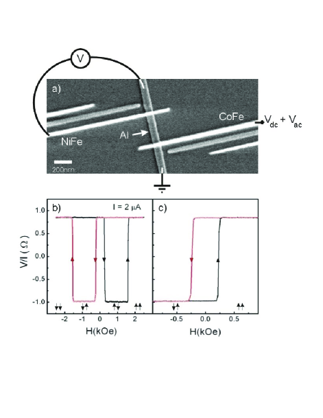
We employ mesoscopic spin valves which have been recently used to demonstrate electrical detection of spin precession and fixed bias spin polarization wees . Our spin valves (Fig. 1a) consist of a CoFe ferromagnetic electrode which “sources” spin-polarized electrons into an aluminum (Al) strip through a tunnel barrier. At a distance from the source there is a second electrode (NiFe) which detects spin polarized electrons in the Al strip by sensing a voltage (the detector is never biased in this experiment).
A current from or into the CoFe source results in an unequal density of spin-up and spin-down electrons in the aluminum wees ; vson with a difference proportional to and the effective polarization of the CoFe electrode, , which characterize the difference between the majority and minority spin populations of the electrons that participate in the tunneling (by definition, where are the tunneling currents for majority and minority electrons and is the total current). This spin imbalance will diffuse in both directions along the Al strip and will reach the detector electrode which will sense a weighted average of the two spin densities by its own polarization, . Therefore, the output voltage is related to the spin degree of freedom and is proportional to wees ; vson . changes sign when the FM relative magnetizations switch from parallel to antiparallel configuration. As described below, by applying a small ac voltage superimposed on a dc voltage and measuring the difference in the detector ac voltage between these two configurations wees , we analyze the dc-bias dependence of the polarization of injected electrons from the CoFe into the Al strip or vice versa com1 . This is analogous to studying the voltage dependence of the TMR in MTJs separating the cathode and anode effects.
We prepare the devices with electron beam lithography and a three-angle shadow evaporation technique to produce tunnel barriers in situ SOV . An aluminum strip (100 nm wide and 6 nm thick) is first deposited through a suspended mask onto a Si/SiO2 substrate using e-beam evaporation with a base pressure lower than Torr. Next, the aluminum is oxidized in pure oxygen (150 mTorr for 20 min) to generate the insulating Al2O3 barriers. Then, without breaking vacuum, the FM electrodes (60 nm wide) are deposited sequentially from two different angles forming tunnel junctions where they overlap with the Al strip. The thickness of the NiFe and CoFe electrodes were chosen to be 20 and 35 nm, respectively to geometrically enhance the difference in the coercive fields which naturally occurs in these materials. The resulting tunnel resistance of the junctions is around 50 k. A small magnetic field of 60 Oe along the FM electrodes was applied during the growth to favor the alignment of their magnetocrystalline and shape anisotropies. The distance between the FM electrodes was varied from 150 to 1,000 nm. The data shown in this paper were acquired for = 220 nm.
The measurements were performed using lock-in techniques by applying a voltage bias () to the source junction (CoFe) and measuring ac voltage at the remote detector junction as sketched in Fig. 1a. Fig. 1b shows a typical spin-valve signal at 4.2 K as a function of an applied in-plane field along the axis of the FM electrodes (). At large enough negative magnetic fields the magnetization of the FM electrodes are pointing to the same direction (parallel configuration). As the magnetic field is swept from negative to positive, a change in the sign of the detector signal is observed at 250 Oe when the magnetization of the NiFe electrode reverses and the device switches from parallel to antiparallel configuration. As the magnetic field is further increased the CoFe flips (at 1.5 kOe ) and a parallel configuration is recovered. Fig. 1c demonstrates that both configurations (parallel and antiparallel) are possible at zero magnetic field and that they can be prepared in a controlled way.
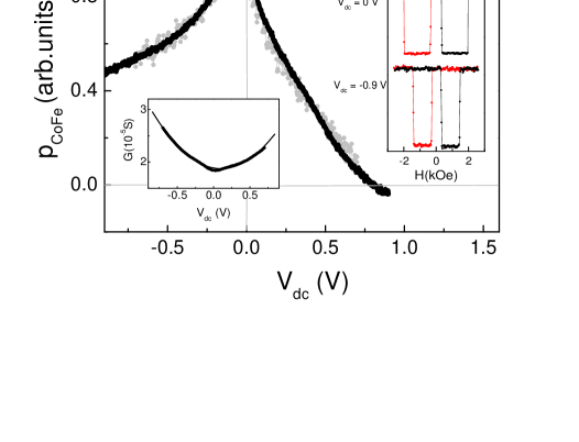
By measuring the output voltage difference between parallel and antiparallel configurations as a function of , we estimate wees the (low bias) polarization of the electrodes to be of the order of 25% at 4.2 K. Note that the larger polarization and the reduction of sample dimensions by an order of magnitude, in particular the distance between the FM electrodes and the Al thickness, help increase the detection signal by a factor of 200 as compared to reported values by Jedema et al. wees . This allows us to perform sensitive dc voltage dependent measurements. In this case, the source junction is excited with both dc and ac voltages. The small ac voltage (30 mV) is used to sense the variation of the polarization as the dc voltage is swept from negative to positive values. The difference in the output voltage for the two relative configurations of the FM electrodes with the ac technique is proportional to where (which are dependent) are the dynamic conductances of the majority and minority electrons and thus is the total dynamic conductance of the CoFe junction. Changes in the transmission of majority and minority spin electrons as a function of bias are clearly illustrated by the dynamic polarization defined as com2 . can then be obtained by dividing the difference in the output voltage for the two relative configurations of the FM electrodes by the dynamic conductance of the CoFe junction (bottom inset in Fig. 2). The magnetic configuration is prepared as shown in Fig. 1c.
The main panel of Fig. 2 shows for two different samples: one measured at 4.2 K and the other at room temperature. The same bias dependence of is observed for both samples and for 4 other samples not presented here. For negative dc biases, electrons are injected from the CoFe electrode into the Al source region. The resulting signal, shown in the main panel of Fig. 2, reaches a maximum around -50 mV and then drops but, even for the largest negative voltages that were applied, the signal is still of comparable magnitude to the one at zero bias. On the other hand, when the electrons are injected from the Al into the CoFe electrode (positive bias), the dynamic polarization drops faster. When V, the detector signal has decreased significantly; it reaches zero at approximately +0.8 V, and it is clearly negative at +0.9 V. The top inset of Fig. 2 shows the output voltage as the magnetic field is swept for different values of the voltage bias. At V, a change in the sign in the voltage switching is clearly seen which implies that, around that bias, the dynamic conductance for minority electrons dominates.
Using a free electron model described below, we calculate the spin currents in the CoFe-Al2O3-Al source junction versus bias, and discuss how these results are related to the experiments above and to the magnetoresistance in magnetic tunnel junctions in general.
The tunnel current through a barrier at finite bias is given by duk ,
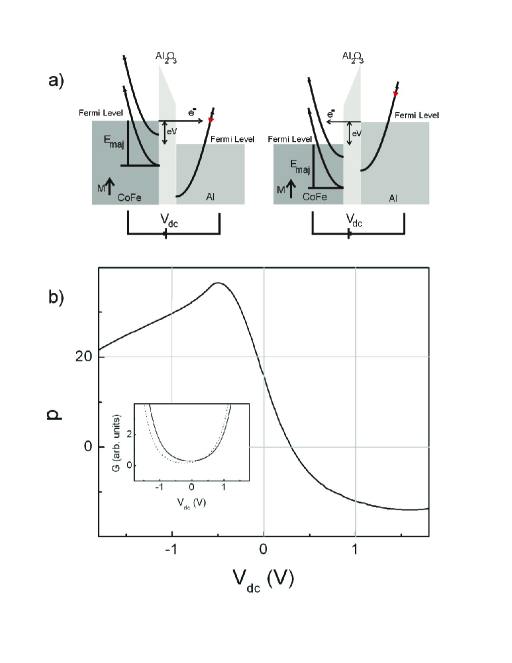
where () are the currents from the left (right) to right (left) electrodes, is the bias-dependent transmission probability, the usual Fermi-Dirac function, the electron charge and Planck’s constant. is found by exactly solving the Schrödinger equation for parabolic free-electron energy bands and a trapezoidal shape tunnel barrier using the Airy wave-function solutions gun within the tunnel barrier (Fig. 3a). In order to calculate the current, first is computed by integrating over all electrons with the same energy, but varying , the component of parallel to the barrier. Then is found by integrating over . As shown in Fig. 3a, the ferromagnetic electrode is characterized by an exchange-split parabolic energy band, which results in majority and minority bands with distinct energies and for the bottom of the bands below the Fermi energy. Note that for Al2O3 barriers, it is likely that the electron bands largely responsible for the tunneling current will have significant character and thus a free-electron like dispersion relation () is justified davis ; st .
The offset of the FM energy bands responsible for tunneling have been derived for Fe from first principles band structure calculations, namely, eV and eV davis ; st . For our calculations we use these values, a Fermi energy for the Al, eV, and a barrier with a thickness of 1.2 nm and a height eV davis . Since spin-flip scattering is neglected, the total current is comprised of two independent electron-tunneling currents associated with spin-up and spin-down electrons. For the negatively biased CoFe-Al2O3-Al junction, the total current is , where is the current from the majority (minority) band to the unpolarized band in the normal metal (Al in our experiment). To compare the simulations with the experimental results in Fig. 2, we calculate the dynamic conductances and the dynamic polarization as defined above .
As seen in Fig. 3b, the calculated dynamic polarization qualitatively follows all the essential features of the measurements in Fig. 2 allowing us to interpret their physical origin. The bias dependence at large negative voltage is weak as in the experimental results; this is a consequence of the narrow energy distribution of the injected electrons around the Fermi energy in the FM. More interestingly, calculations at positive bias show a large bias dependence of the dynamic polarization as well as a sign change as found experimentally. By analyzing the tunneling for the majority and minority spin band electrons, we conclude that the large drop in is partially caused by the decrease of density of states ratio between the two spin bands for electrons tunneling into hot states, as shown in the right panel of Fig. 3a. However, it is evident from inset in Fig. 3b that becomes larger than above 0.4 V, causing a sign change. A sign inversion cannot be explained with only a decreasing density of states ratio between minority and majority band electrons. Instead, we have found numerically that the transmission through the barrier is largest when the total electron energy is equal to the effective barrier height (this is when the absolute value of electron and (imaginary) barrier wave vectors are equal), creating a wave vector matched state which will occur at different biases for the two spin bands in the FM. Specifically, around 0.5 V, eV = 1 eV is closer to eV than eV = 3 eV. In other words, the matching of the minority band improves with increasing bias, whereas the matching of the majority band deteriorates. As a consequence the relative increase in the tunneling of minority electrons is faster than expected by simple density of state considerations.
Note that the measurements in Fig. 2 seem displaced towards positive biases as compared to the simulations in Fig. 3b. This could be accounted by an asymmetry between the CoFe-Al2O3, Al2O3-Al barrier heights that is not considered in our model brinkman .
We find that our experimental and numerical separation of the ferromagnetic electrodes forms a solid basis for understanding the physical processes responsible for voltage dependence of TMR and tunnel spin injection-accumulation in general. The presented results demonstrate that even when TMR is zero, the transfer of spin polarized electrons from the cathode is still possible and that the anode is responsible for the quenching of the magnetoresistance. This could explain recent results by Fuchs et al. fuc in nanoscale MTJs where it was shown that spin-transfer switching can occur in the absence of TMR at high bias, meaning that the junction current is still polarized. It is also worth noting that interesting and complex bias dependencies can be obtained by engineering magnetic tunnel barriers interfaces and using composite barriers fau ; sharma ; jm . This illustrates the importance of studying all the aspects of the quantum mechanical properties of the tunneling process before ascribing complex results to an unusual density of states of the material.
In conclusion, we have measured the voltage dependence of the tunneling polarization of electrons from and into a ferromagnet emphasizing the intrinsic asymmetry between these two processes. We found that the polarization is strongly suppressed for electrons tunneling into the ferromagnet due to the reduced polarization for hot electron states and a spin-dependent wave-vector mismatch.
This research was supported in part by NSF grants DMR-0244441 and NSEC-PHY-0117795 and ONR grant N00014-02-1-0055.
References
- (1)
- (2) M. Julliére, Phys. Lett. 54A, 225 (1975).
- (3) J.S. Moodera, L.R. Kinder, T.M. Wong and R. Meservey, Phys. Rev. Lett. 74, 3273 (1995).
- (4) T. Miyazaki and N. Tezuka, J. Magn. Magn. Mat. 139, L231 (1995).
- (5) M. Tsunoda et al., Appl. Phys. Lett. 80, 3135 (2002).
- (6) J. Faure-Vincent et al., Appl. Phys. Lett. 82, 4507 (2003).
- (7) S. Zhang et al., Phys. Rev. Lett. 79, 3744 (1997).
- (8) J.S. Moodera, J. Nowak and R.J.M. van de Veerdonk, Phys. Rev. Lett. 80, 2941 (1998).
- (9) D. Nguyen-Manh et al., Mater. Res. Soc. Symp. Proc. 492, 319 (1998).
- (10) M. Sharma, S.X. Wang and J.H. Nickel, Phys. Rev. Lett. 82, 616 (1999).
- (11) J.M. de Teresa et al., Science 286, 507 (1999).
- (12) P. Mavropoulos, N. Papanikolaou, and P. H. Dederichs, Phys. Rev. Lett. 85, 1088 (2000).
- (13) A.H. Davis and J.M. MacLaren, J. Appl. Phys. 87, 5224 (2000).
- (14) F. Montaigne, M. Hehn and A. Schuhl, Phys. Rev. B64, 144402 (2001).
- (15) F.J. Jedema et al., Nature 416, 713 (2002).
- (16) P.C. van Son, H. van Kempen and P. Wyder, Phys. Rev. Lett. 58, 2271 (1987).
- (17) Note that the roles of the FM electrodes are interchangeable. The NiFe and CoFe electrodes can both be used as source or detector. In either case, the results are similar; we focus on the tunneling through the CoFe.
- (18) S.O. Valenzuela and M. Tinkham, to be published.
- (19) Note that the dynamic polarization, , measures contributions from electrons within a narrow energy range for each bias voltage whereas the current polarization, , includes contributions from all electrons.
- (20) C.B. Duke, Tunneling in Solids (Academic Press, New York, 1969).
- (21) K.H. Gundlach, Solid State Electronics 9, 949 (1966).
- (22) M.B. Stearns, J. Magn. Magn. Mat. 5, 167 (1977).
- (23) W.F. Brinkman, R.C. Dynes and J.M Rowell, J. Appl. Phys. 41, 1915 (1970).
- (24) G.D. Fuchs et al., cond-mat/0404002.