The steady state in noncollinear magnetic multilayers
Abstract
There are at least two different putative steady state solutions for current across noncollinear magnetic multilayers; one has a discontinuity in the spin current at the interface the other is continuous. We compare the resistance of the two and find the solution with the continuous spin currents is lower. By using the entropic principle we can state that this solution is a better estimate of the resistance for a noncollinear magnetic multilayer
pacs:
72.25.-b,72.15.Gd, 73.23.-byear number number identifier
When current is driven across a multilayered structure in which the magnetic layers are not collinear one has to consider how the spin polarized current is transmitted between layers. In most treatments one considers the components of the spin current transverse to the magnetization of a layer is either absorbed or reflected at the interface upon entering the layer and that this is the origin of spin torque created by spin currents in magnetic multilayers slon-berger . This scenario does not envisage the existence of components of the spin accumulation that are transverse to the magnetization of the layer into which they are injected by the charge current, but it does assume a steady state of the current is reached, e.g., one posits that there is no time dependence of the current densities. An alternate proposal is to inject transverse spin currents through interfaces that propagate in transition-metal ferromagnets, e.g., in Co up to 3 nm from the interface, and to have the spatial variation of the spin currents balanced by transverse spin accumulation thereby achieving steady state.jianwei In this case the spin currents create an accumulation which acts as a torque on the background rather than directly suppling angular momentum to the background magnetization.spin diffusion When the current drives a system out of equilibrium it is not immediately obvious which of the two scattering processes around the interfaces better describe the steady state transport across a multilayered structure. To resolve this question we use the variational principle of transport that says that: “in the steady state, the currents are such that the production of entropy has the largest value consistent with its subsequent conservation.” ziman We find in the steady state transverse spin currents with their attendant accumulations do exist in magnetic layers in the immediate region about the interface, i.e., within several nm. Their existence determines the amount of spin torque created on a magnetic layer for a fixed current; therefore it changes one’s predictions of the critical current needed to switch the magnetization in a multilayered structure.expts
The experiments that have demonstrated current induced magnetization reversal have been done on nanopillars that consist of two magnetic layers separated by a nonmagnetic spacer to magnetically isolate the layers, but otherwise transmit the spin polarized current from one layer to the other, and nonmagnetic leads.expts To resolve the issue of how the spin polarized current created in one layer is transmitted to another noncollinear layer we solve for the transport across two magnetic layers and assume the nonmagnetic spacer is thin enough to be neglected, i.e., when one drives a spin polarized current across the trilayer one uses spacer layer thicknesses small compared to the spin diffusion length so that one can coherently transmit spin information from one ferromagnetic layer to the other;expts the analysis can be repeated with a finite spacer without changing our conclusions. We solve the Boltzmann equation for current across the layers by using the interface scattering matrix to relate the distribution functions across their common interface to self-consistently determine the accumulations and currents in each layer, e.g., see Waintal and Bauer.bauer The additional resistivity due to the noncollinearity of the layers is found from the change in chemical potential that develops across the structure, e.g., see Valet and Fert.vf While this is proportional to the angle between the magnetization of the layers, it also depends on whether the scattering at the interface is able to create spin flips; recently we have shown that they are induced by currents in noncollinear magnetic multilayers.levy By determining the change in chemical potential across the two layered structure we use the variational principle, that holds that the electrical resistivity is a minimum in the steady state,ziman to discern which scattering at the interface achieves the lowest resistance and therefore is the best description for a steady state spin current in noncollinear multilayers.
We consider two bands crossing the Fermi surface of a ferromagnet, a majority spin band and one minority; this is appropriate for example for Co where the two additional minority bands could be included but do not add much to the transport across the interface when the layers are noncollinear. Our Boltzmann equations for two band are,jianwei
| (1) |
| (2) |
where for majority or for minority, is the exchange splitting between the state on the Fermi surface and its partner with the same momentum and opposite spin,jianwei and and represent spin dependent but non-spin-flip and spin-flip relaxation times. Also, represent the transverse relaxation time; in our calculation we take as it does not affect the point we are making in this paper. The distribution functions and are functions of momentum and position; the angular brackets on the right hand side of Eqs.(1) and (2) denote averages over the Fermi surface. In our notation each band crossing the Fermi surface is represented by a spinor distribution function; these are statistical density matrices which characterize the out of equilibrium state of the current. The first equation refers to the longitudinal or spin diagonal component on the distribution function on the Fermi surface, and the current induced coherences with states off the Fermi surface are given by the second equation. We do not write an equation for the excited state itself as it is not occupied in equilibrium; this term corresponds to the second longitudinal or diagonal component of the spinor. As we limit our current analysis to linear response in the electric field we do not consider it further here.
As we consider two bands, , there is a spinor for each sheet of the Fermi surface. For specificity we rewrite the distribution functions as,
| (3) |
where the prime denotes an excited state. Note that although there is scattering on the Fermi surface to produce finite values for we do not consider these components because their contribution to the current cannot be calculated in the Boltzmann approach as there is no unique velocity associated with them.jianwei ; stiles-slon As we have coherences with excited states of opposite spin, and not only with states of opposite spin on the Fermi surface, we have in linear response six components of the distribution functions to keep track of in each layer which is nearly twice the number when one limits oneself to scattering on the Fermi surface. The boundary condition for these functions at the interface are,bauer
| (4) |
| (5) |
where or . The transmission and reflection coefficients ( probabilities) are
| (6) |
where , and the amplitudes should be determined from ab-initio calculations. kelly These coefficients have been determined for interfaces between ferromagnetic and normal (F/N) metals for states that exist on the Fermi surface when the system is in equilibrium; in this case states of opposite spin are coherent in the normal layer but not in the ferromagnet when one uses a single particle description for the electron states. For this reason distribution functions in the ferromagnetic layer only with exist when the components are referred to the axis of the magnetization of the layer. We have recently shown that to calculate the conductivity of noncollinear magnetic multilayers by using a local layer-by-layer approach it is necessary to include additional scattering at the F/N interfaces; this produces so called current induced coherences in the ferromagnetic layers, i.e., components of the distribution function with .levy In contrast to the case when one neglects these current induced coherences we have 16 components of to consider.
To discuss transport across a noncollinear F/N/F trilayer we write the transmission and reflection amplitudes and coefficients in terms of the F/N scattering coefficients discussed above. We will make the simplification of neglecting the additional scattering at the F/N interfaces arising from differences in the band structure between the ferromagnetic and normal layers, i.e., we overlook differences between and , but we do consider ; this oversight in no way alters the primary conclusion we arrive at. When the thickness of the normal spacer is small compared to the spin diffusion length there is no loss of spin information and one can write the scattering amplitudes and coefficients connecting the ferromagnetic layers in terms of those for the F/N interfaces.bauer We use the variational principle cited above to determine whether non spin-flip or spin-flip scattering at the interface yields the best estimate for the resistivity. To calculate the angular dependence of the reflection and transmission due to this perturbation we use the spin rotation matrices to refer the states quantized along the magnetization of one F layer in terms of states quantized along the magnetization of the other F layer. In the limit of neglecting the non-spin-flip scattering at the individual F/N interfaces in which the electron stays on the same sheet of the Fermi surface we find for the majority state the transmission amplitudes are
| (7) |
| (8) |
| (9) |
| (10) |
where are the Fermi momenta of the majority and minority bands, the angle between the magnetic layers, and parameterizes the amplitude arising from current induced spin-flip scattering at the F/N interfaces; corresponds to no spin flip scattering which is the conventional assumption. The half angle terms arise from the spin rotation matrices while the comes from the magnitude of the current induced spin-flip scattering.levy For the transmission amplitudes of the minority state we replace , and . When we include the scattering at the F/N interfaces that comes from and are less than when , but this does not change the conclusions we arrive at here.scattering
For the reflection amplitudes we write for the majority state
| (11) |
| (12) |
| (13) |
while those for the minority state are obtained by the following replacements , and .The unitary of scattering matrix can be confirmed as . Based on a specific mechanism, e.g., the current induced spin-flip suggested in Ref.(8), the values for and can be determined, but their precise values are unimportant to our argument; only their existence is crucial.
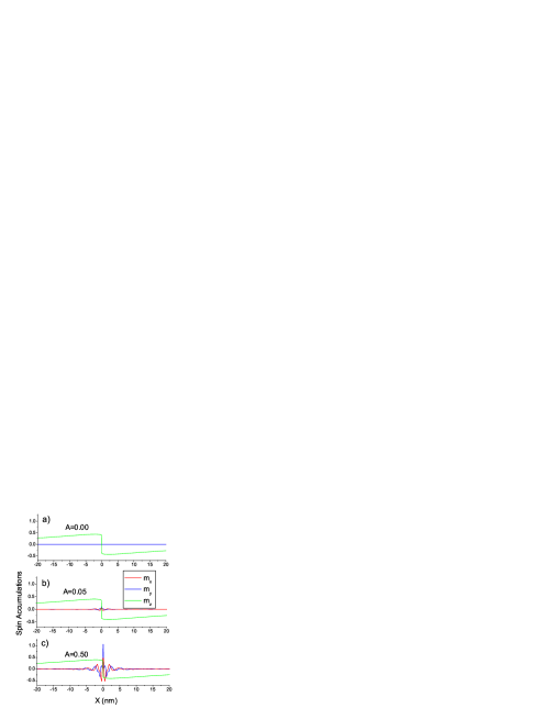
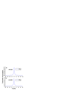
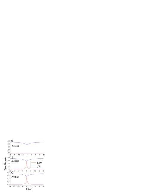
To determine whether current induced spin-flip scattering is needed to achieve steady state current conditions we compared the resistance for to the resistance one finds for ; as our result is not sensitive to the values for them, in our calculations we consider two set of values and . Also we used the Fermi momenta for Co zahn so that . We solved Eqs.(1) and (2) for the out of equilibrium spin transport across two noncollinear magnetic Co layers by using the above transmission and reflection amplitudes and the coefficients Eqs.(6) to match the out of equilibrium distribution functions across the F/N/F interface. In Figs. 1 through 3 we compare the spin accumulations and currents across the interfacial region for the three sets of , for . For there is no transverse accumulation nor current (; only the longitudinal component of the spin current exists in the ferromagnetic layers as expected. For the transverse spin current exists and is independent of the amount of spin-flip scattering at the interface; only the amount of transverse accumulation depends on the and . From Fig.2 we see that the length scale of the transverse accumulation () does not depend on ; rather it is controlled by the exchange splitting in Eq.(2) for the transverse distribution function. Note that the vertical scales for the accumulation in Figs.2 differ by a factor of ten, so that the transverse accumulation is nearly linear dependent on the spin-flip scattering parameter .
The additional resistance due to noncollinearity of layers is found from the additional voltage drop of the electrochemical potential; see Valet and Fert.vf In the present notation this electrochemical potential is defined as where the brackets denote averages over the Fermi surface, and the additional resistance is
| (14) |
where , is the mean free path in the bulk of the metal, and for Co the ratio of the Fermi velocities is . While the integral is over the entire structure we can cut it off when the chemical potential is independent of position. As the spin diffusion length for a typical 3d transition-metal, e.g., Co, is of the order of nm we have limited the integration to nm about the interface. We have calculated the resistances for the three sets of and as a function of angle and present our results in Fig.4. While the lowering of the resistance is proportional to the amount of current induced spin-flip scattering ( and ) the signal conclusion is that as long as and are nonzero the resistance is always lower than for We conclude that when the spin current is discontinuous at the F/N interfaces, i.e., the resistance is always larger than when the current is continuous (). By invoking the principle that the electrical resistance is a minimum in the steady state of the current, we conclude that the spin-flip interface scattering is necessary to achieve steady state conditions.
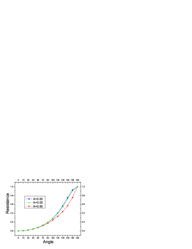
The resistance shown in Fig.4 can be written as
| (15) |
where is the resistance coming from the band mismatch at the F/N interfaces, i.e., ; we have set this to zero in our calculation. For we are able to fit our results to the form suggested bypratt
| (16) |
and we find . For ; while for this form does not provide a suitable fit to the angular dependence of the resistance. However when we use
| (17) |
we are able to obtain an excellent fit with for .
In equilibrium only states up to the Fermi level are occupied and the scattering at the F/N interfaces is characterized by . When the current is switched on the current induced spin-flip scattering at the interfaces induces coherences between states on the Fermi surface and excited states of opposite spin. This injection of transverse components of the spin current is offset by the interference coming from the individual states on the Fermi surface,fert-stiles so that after a characteristic length the current is parallel to the background magnetization; from Fig.3 we can see that .spin diffusion While in linear response we are only interested in the coherences between the spin states on the Fermi surface and the excited states of opposite spin , it follows from the inequality for density matrices representing statistical mixtures of states that
| (18) |
i.e., the presence of coherences indicate that there is an occupancy of the excited state when the system is out of equilibrium; albeit it is a higher order effect. As the transverse components of the spin current disappear close to the interface (within 3-5 nmspin diffusion ) the time required to achieve this “equilibrium” is short compared to the spin-flip time that equilibrates the longitudinal components of the spin current.
The existence of finite current induced coherences close to the interface give rise to the transverse spin accumulations found in this and previous studies; it should be stressed that our self consistent solutions of the Boltzmann equation do not mandate transverse spin accumulation, rather they are found to be necessary concomitant to achieve a steady state in noncollinear magnetic structures.spin diffusion It is in this sense that our calculations indicate that spin-flip scattering at the interfaces is necessary to achieve steady state current conditions in a noncollinear multilayered structure. Finally, the time necessary for creating the transverse spin accumulation is short compared to that for the longitudinal; this is controlled by the spin-flip time which for Co is of the order of sec. Both times are short compared to the time it takes for the background magnetization to move, sec.; therefore one can achieve steady state currents in noncollinear magnetic structures prior to magnetization reversal provided one allows for transverse spin accumulation in the regions about the interfaces. Conversely, if one does not allow this one cannot achieve steady state conditions in noncollinear magnetic structures.
In conclusion, in the calculations whose results we presented we have taken into account differences in the band structures in the ferromagnetic layers, i.e., . In the conventional approach, , there is a discontinuity in the spin current at the N/F interfaces, while in our approach, , there is none. Therefore the origin of the discontinuity cannot be the band mismatch per se; rather the key difference between the two scenarios is that we account for the coherence between states of opposite spin in the ferromagnetic layers that is lost in effective single electron treatments. When we account for these coherences in our model with spin split bands in the ferromagnetic layers the spin currents are close to those found in previous calculations based on unsplit free electron bands (which maintain coherences throughout the multilayer).
We would like to acknowledge very helpful discussions with Jerry Percus on the use of the resistivity minimum principle for steady state currents, and to Shufeng Zhang on general transport theory. This work done under a grant from the National Science Foundation(Grant DMR 0131883).
References
- (1) J.C. Slonczewski, J. Mag. Mag. Mater. 159, L1 (1996); ibid 195, L261 (1999); L. Berger, Phys. Rev. B 54, 9353 (1996); J. Appl. Phys. 89, 5521 (2001); A. Brataas, Yu.V. Nazarov, and G.E.W. Bauer, Phys. Rev. Lett. 84, 2481 (2000) and D.H. Hernando, Y.V. Nazarov, A. Brataas, and G.E.W. Bauer, Phys. Rev.B 62, 5700 (2000); Alexey Kovalev, Arne Brataas and Gerrit E.W. Bauer, ibid 66, 224424 (2002); M.D. Stiles and A. Zangwill, Phys. Rev. B 66, 014407 (2002); M.D. Stiles and A. Zangwill, J.Appl. Phys. 91, 6812 (2002); J.C. Slonczewski, J. Mag. Mag. Mater. 247, 324 (2002); Gerrit.E.W. Bauer, Yaroslav Tserkovnyak, Daniel Huertas-Hernando and Arne Brataas, Phys. Rev. B 67, 094421 (2003).
- (2) Jianwei Zhang, P.M. Levy and Shufeng Zhang, Bull. Amer. Phys. Soc. 48, 117 (2003); P.M. Levy, Jianwei Zhang and Vladimir P Antropov, ibid 48, 821 (2003); Jianwei Zhang, P.M. Levy, Shufeng Zhang and Vladimir P Antropov, to be published.
- (3) S. Zhang, P.M. Levy and A. Fert, Phys. Rev. Lett. 88, 236601 (2002); A. Shpiro, P.M. Levy and S. Zhang, Phys. Rev.B 67,104430 (2003).
- (4) See Electrons and Phonons by J.M. Ziman ( Oxford at the Clarendon Press, London 1972); see pp. 275-285.
- (5) J. A. Katine, F. J. Albert, R. A. Buhrman, E. B. Myers, and D. C. Ralph, Phys. Rev. Lett. 84, 3149 (2000); F. J. Albert, J. A. Katine, R. A. Buhrman, and D. C. Ralph, Appl. Phys. Lett. 77, 3809 (2000); J. Grollier, V. Cros, A. Hamzic, J. M. George, H. Jaffrès, A. Fert, G. Faini, J. Ben Youssef, and H. Legall, Appl. Phys. Lett. 78, 3663 (2001); B.Özyilmaz, A. D. Kent, D. Monsma, J. Z. Sun, M. J. Rooks, and R. H. Koch, Phys. Rev. Lett. 91, 067203 (2003); S. Urazhdin, Norman O. Birge, W. P. Pratt, Jr. , and J. Bass, ibid, 146803 (2003).
- (6) X. Waintal, E.B. Myers, P.W. Brouwer and D.C. Ralph, Phys. Rev.B 62, 12 317 (2000); Gerrit E.W. Bauer,Yaroslav Tserkovnyak, Daniel Huertas-Hernando and Arne Brataas, Adv. in Solid State Physics, 43, 383 (2003). Note that states only on the Fermi surface in equilibrium are considered in these references; here we include the current induced coherences found in Ref. XXXX.
- (7) T. Valet and A. Fert, Phys. Rev. B48, 7099 (1993).
- (8) P.M. Levy and Jainwei Zhang, ”Current induced spin flip scattering at interfaces in noncollinear magnetic multilayers”, to be published.
- (9) M.D. Stiles and A. Zangwill, Phys. Rev. B 66, 014407 (2002); J.C. Slonczewski, J. Mag. Mag. Mater. 247, 324 (2002); M.Zwierzycki, Y. Tserkovnyak, P.J. Kelly, A. Brataas, and G.E.W. Bauer, cond-mat/0402088 3 Feb. 2004.
- (10) K. Xia, P. J. Kelly, G. E. W. Bauer, A. Brataas, and I. Turek, Phys. Rev.B 65, 220401 (2002).
-
(11)
For the F/N/F trilayer we can take into account the
non-spin-flip scattering at the F/N interfaces, i.e., .
If we neglect multiple reflections.between the interfaces the transmission
amplitudes connecting the two ferromagnetic layers can be written as
(19) (20)
and(21)
From these we can see that the trilayer scattering has the same angle dependence as indicated above for . When we include the angular dependence coming from multiple reflections they enter in the demominator of the transmission amplitudes ( see Ref.6), and complicate its’ angular dependence. However for the 3d transition-metal normal metal interfaces we consider, e.g., Co/Cu, the dominant transmission is carried by the majority band and the reflection in this channel is small; therefore the correction due to multiple reflections is quite small.(22) - (12) Peter Zahn and Ingrid Mertig, private communication.
- (13) S. Urazhdin, R. Loloee and W.P. Pratt Jr, cond-mat/0403441, 17 Mar 2004; see their Eq.1 and reference 15.
- (14) If one injects the transverse components of the spin current at a point the ensuing radial currents move outward and do not interfere. However in a multilayered structure they are injected across a plane, i.e., the interface, so that waves emanating from different points across the surface take different times to arrive at a point away from the interface. This was first presented by Albert Fert at the International Symposium on Metallic Multilayers (MML’01) 24-29 June 2001, Aachen, Germany; see also M.D. Stiles and A. Zangwill, Phys. Rev. B 66, 014407 (2002) for an excellent discussion of how oscillating but non-decaying functions can interfere to produce a seemingly exponential decay.