Peeling from a patterned thin elastic film
Abstract
Inspired by the observation that many naturally occurring adhesives arise as textured thin films, we consider the displacement controlled peeling of a flexible plate from an incision-patterned thin adhesive elastic layer. We find that crack initiation from an incision on the film occurs at a load much higher than that required to propagate it on a smooth adhesive surface; multiple incisions thus cause the crack to propagate intermittently. Microscopically, this mode of crack initiation and propagation in geometrically confined thin adhesive films is related to the nucleation of cavitation bubbles behind the incision which must grow and coalesce before a viable crack propagates. Our theoretical analysis allows us to rationalize these experimental observations qualitatively and quantitatively and suggests a simple design criterion for increasing the interfacial fracture toughness of adhesive films.
I Introduction
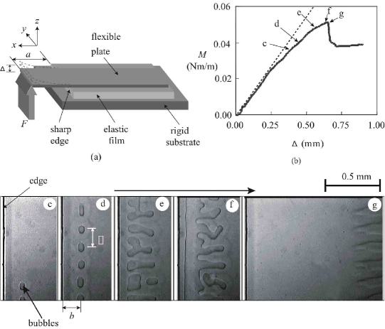
The propagation of a crack on a smooth thin layer of adhesive (Kaelble 1965, Gent et al. 1975, Kendall 1975 & Kinloch et al. 1994) has been extensively studied using peel experiments. Although this model problem is of much relevance in understanding the mechanical behavior of artificial adhesives, naturally occurring adhesive surfaces in animals and insects in particular present complex structural morphologies to alter the physics of adhesion (Scherge and Gorb 2001). To explore the mechanisms of crack initiation and propagation on these textured interfaces, we study the initiation propagation of cracks on model adhesive layers which are patterned by sharp cuts and discontinuities using a simple cantilever plate peeling experiment (see Fig. 1a). A flexible plate, in contact with a thin film of adhesive which remains strongly bonded to a rigid substrate, is lifted to initiate a crack from the edge of the adhesive and the load-displacement curve is monitored to quantify the force and energy required for crack initiation.
II Experiment
We use thin films of polydimethylsiloxane (PDMS) as a model adhesive film in our experiments. These crosslinked elastomeric films of shear modulii between 0.2 - 3.1 MPa are prepared by following the procedure described in Ghatak and Chaudhury 2003. JKR (Johnson, Kendall and Roberts, 1971) contact mechanics experiments of the networks indicate that they are purely elastic and exhibit no hysteresis. The film is strongly adhered to a rigid substrate which is attached to the stage of a microbalance. Microscope cover slips coated with self assembled monolayer (SAM) of Hexadecyltrichloro silane (HC), hexafluorodecyltrichlorosilane (FC) molecules and with long chain (MW ) PDMS molecules which can be brought into and out of contact with the adhesive layer are used to explore the mechanics of peeling. The glass plate and the adhesive elastic film are first rinsed thoroughly in de-ionized water to remove any static charge and blow dried in nitrogen gas. We use a sharp razor blade to make periodic incisions in the adhesive film (Fig. 1a) that are used to arrest cracks and provide a barrier for their nucleation. We then bring the flexible plate in complete contact with the elastic film and keep it so for thirty minutes before quasi-statically lifting the plate at a distance away from the edge (Fig. 1 a) using a micromanipulator that allows us to measure the vertical displacement of the plate end , while the microbalance allows us to simultaneously monitor the load . During this entire process, we view the contact zone near the edge of the film using an optical microscope equipped with a CCD video camera to study the morphology of adhesion during the process of crack initiation.
Crack initiation at a single discontinuity: In Fig. 1c-g we show a typical sequence of events leading to crack initiation when a glass plate is lifted at a slow but constant rate from the adhesive film. Initially the load increases linearly with the displacement () of the plate. As the displacement is increased beyond a threshold, the moment increases sub-linearly; this process is accompanied by the nucleation of a series of cavitation bubbles (Fig. 1 c) behind the edge. Although all the bubbles do not all nucleate at the same time (Fig. 1c - d) as is increased, they are periodically spaced with a well-defined separation wavelength . Once this array of bubbles is established behind the edge, a further increase in causes the existing bubbles to grow and coalesce (Fig. 1e - f) until they eventually reach the edge of the adhesive film (Fig. 1g). The almost straight crack that results moves and reaches an equilibrium position determined by the competition between plate bending and film shearing in a displacement controlled experiment. If the lift-off displacement is now reduced gradually this sequence is played out in reverse and the crack closes as the plate reattaches to the film everywhere except along a few uniformly spaced bubbles close to the edge. Over relatively long times, the bubbles disappear and homogeneous contact between the cover plate and the adhesive film results. In this confined system, cavitation does not occur randomly as thought previously (Gent et al. 1958, Kaelble 1971 & Lakrout et al. 1999); but instead is a manifestation of an adhesion induced instabilities (Ghatak et al. 2003) that leads to the formation of the periodically spaced bubbles with a wavelength (Ghatak et al. 2000).
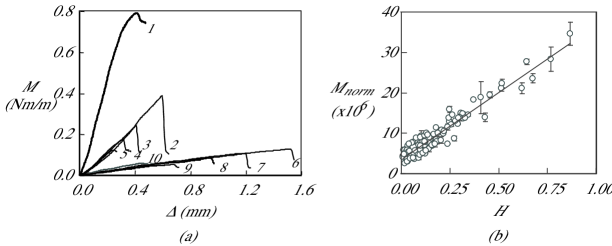
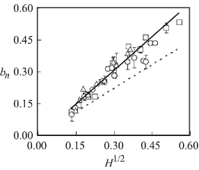
Fig. 2 shows the peeling moment, as a function of the displacement of the plate for a variety of film thicknesses (m) and cover plate rigidities ( Nm). For each cover plate, the peeling moment increases with displacement until , the maximum peeling moment corresponding to crack initiation. A further increase in causes to drop abruptly to a much lower value as the crack then proceeds to propagate on the smooth adhesive film. In Fig. 2b), we plot the scaled maximum moment ( is the van der Waals stress associated with a separation distance , being the Hamaker constant between the two surfaces) as a function of the scaled thickness and see that varies linearly with . Similar linear relationships persist when the cover plates are coated with other self-assembled monolayers such as those made of FC and PDMS. In Fig. 3, we show that the distance of the cavitation bubbles from the edge of the film follows the scaling law .
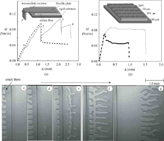
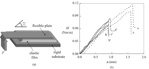
Crack Initiation at multiple discontinuities: Similar experiments were also carried out on elastic films with multiple parallel incisions ( mm apart) which span the width of the film. In Fig. 4a, we show a typical load-displacement curve for this situation and see the signature of stick slip behavior. Video micrographs in Fig. 4c-g show the sequential crack arrest and initiation on such an incision patterned film. Here, the crack initiates from one such incision at a sufficiently high load but gets arrested at the next one. Surprisingly, the crack front stops before it reaches the next incision (Fig. 4c) and remains there while bubbles nucleates on the opposite side (Fig. 4d-f) of the incision. Finally, the two fronts meet at the incision (Fig. 4g) forming a crack that then propagates rapidly. When the experiment is repeated on a two-dimensional textured and patterned surface prepared by using a mould (inset of Fig. 4b) multiple crack arrest and initiation events lead to a high peeling moment (solid line) which remains constant and does not show the stick-slip like characteristics for incisions that are widely separated. As we will see later, the disappearance of the stick-slip behaviour is associated with the fact that the characteristic length scale of the texture is smaller than a critical threshold. In such a situation, since the peeling moment is much higher than that on a smooth adhesive film, we see that the fracture toughness of the interface is also significantly enhanced by texturing, quite contrary to normal intuition.
Obliquity of the edge: To understand the role of the edge in crack initiation, we also carried out experiments on films in which the incision makes an angle different from (Fig. 5a). In Fig. 5b we plot the peeling moment as a function of displacement for various and see that changes in affect the crack initiation moment more significantly for thick films than for thin ones. As the critical peeling moment becomes smaller and smaller, consistent with the fact that when there is no edge at all so that there is no barrier for crack initiation, and suggests that is a measure of crack blunting. Further experiments are needed to quantify this effect and will be subject of future study.
III Theory
We now turn to an approximate theory to rationalize our experimental findings. Assuming that the adhesive film is incompressible, linearly elastic and loaded in plane strain, the equations of equilibrium are
| (1) |
Here and elsewhere , is the pressure in the elastic film, and are the components of displacement field in the and directions (Fig. 1 a), and is the shear modulus of the adhesive. The pressure itself is determined by the constraint of incompressibility, which in its linearized form can be written as
| (2) |
With the origin of coordinate system at the corner of the incision in the film , as shown in Fig. 1a, the corresponding boundary conditions (b.c.) are
| (3) | |||||
Here is the vertical displacement of film at , and is the distance of the line of application of the peeling force from the contact line . For a thin film with a large lateral length scale , vertical gradients in the displacement fields are much larger than horizontal gradients , so that we may use the lubrication approximation (Batchelor, 1967). Then , and and the equations of equilibrium (III) simplify to
| (4) |
| (5) |
Substituting (5) into the depth-integrated continuity equation (2) and linearizing the result leads to an equation for the vertical displacement of the cover plate in the region where it is attached to the adhesive film
| (6) |
In the region where the film is not in contact with the plate, the displacement of the cover plate satisfies
| (7) |
Since the film must be flat far away from the contact line
| (8) |
Continuity of the displacement, slope, bending moment, vertical shear force and the pressure at the contact line imply that
| (9) |
Finally, at , where the flexible plate is freely pivoted while being lifted vertically by an amount , the boundary conditions are
| (10) |
We pause briefly to consider the assumptions inherent in our approach. Lubrication theory clearly must break down over a length scale of order from the edge. However, if we consider variations over scales much larger than , these edge effects can be safely ignored. As we shall see later, this is indeed the case. The edge of the incision where the plate first loses contact with the elastic film acts to pin the contact line. This allows us to specify the deflection of the plate and the distance of the contact line from the point of application of the force independently. This is in contrast to the case of a flexible plate in contact with a smooth elastic film, where it is not possible to specify both and since there is a relation between them in terms of the work of adhesion.
Solving (6) subject to (8-10) for the interfacial displacement leads to
| (13) |
where and are two characteristic lengths that arise naturally in the problem. The scale determines the lateral extent of the film over which the peeling deformation is felt; on scales larger than (13) shows that the interface displacement decays exponentially. For typical experimental parameter values, , so that crack tip and edge effects are relatively small. Using (6) we can now determine the normal traction on the surface of the film which, in the lubrication approximation, is given by . For long wavelength deformations so that
| (14) |
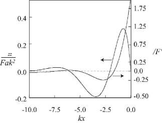
where . In Fig. 5 we show the variation of the vertical displacement and the normal traction . We note that both the displacement and the traction are oscillatory with exponentially decaying amplitudes; in particular the normal traction has a negative maximum at a distance from the edge, given by
| (15) |
where the pressure
| (16) |
This large tensile traction at some distance behind the contact line rationalizes our observations of cavitation bubbles. However the characteristic periodicity of the bubbles in the transverse direction (parallel to the contact line) with a wavelength (Ghatak and Chaudhury, 2003) requires a three-dimensional stability analysis of the planar solution and is beyond the scope of the current study. Here the role of the incisions is to pin the contact line and prevent the crack from being initiated until a threshold stress is reached, thus raising the effective toughness of the interface. Our experimental observations of the dimensionless cavitation bubble nucleation distance shown in Fig. 3 are qualitatively consistent with (15) although quantitatively there is a discrepancy of about . This could be due to the use of the particular boundary condition that the pressure is continuous at the contact line . If we replace this by a different boundary condition , and calculate by minimizing the total energy of the system, we get , in accordance with our experimental measurements. In fact, the actual condition at the contact line is determined by the details of the microscopic interaction between the two surfaces and is probably somewhat intermediate between these two cases.
The exponentially decaying stress profile (Fig. 6) also explains why the crack gets arrested before it reaches the an incision. Since the normal traction vanishes at the incision, the next crack is initiated via bubble nucleation and coalescence on the other side of the incision and the whole scenario repeats itself. When the distance between incisions becomes of the order of or less than the characteristic stress decay length the crack feels the effect of incisions continuously, and the intermittent behavior of the peeling moment is replaced by a much higher constant value for a finely textured surface (Fig. 4(b)).
To obtain the stress associated with bubble nucleation, we rearrange equation (16) so that
| (17) |
Here is the critical stress associated with bubble nucleation, which can be determined by comparing (17) with our experimental data and yields N/m2. For comparison, with a Hamaker constant J, a separation distance Å the van der Waals pressure, N/m2. The experimentally obtained low value of suggests that the two surfaces do not remain in perfect contact and are separated by an average distance of Åpossibly due to the intrinsic roughness of the adhesive films. However, our experiments even with films of very low root-mean-square roughness ( Å) results in a low critical stress ( N/m2), signifying that other factors may be responsible as well.
IV Discussion
In this note, we have demonstrated the qualitative difference between crack initiation and crack propagation in the context of peeling a flexible plate from a thin textured adhesive film. The origin of this difference may be ascribed to the formation of cavitation bubbles behind the contact line which increases the load required for peeling by creating a convoluted crack front. A different way of enhancing the load for crack initiation is to use films with oblique incisions, and leads to effective way of blunting or sharpening the crack tip. A simple theory allows us to explain these observations qualitatively and quantitatively, and leads to a design criterion for enhancing the interfacial fracture toughness of a flexible plate in contact with an adhesive film: the pattern has to be microstructured on a length scale smaller than or equal to the stress decay length .
We finally return to our motivation of biological attachment devices (Scherge et al. 2001) which show a variety of textured contact surfaces. Our experiments on model patterned systems suggest that the enhanced fracture toughness in these biological settings is a rather subtle effect owing to the difference between crack initiation and propagation on a patterned surface. Multiple crack arrest and initiation on these surfaces results in the dissipation of the elastic energy in much the same way as for fracture of soft elastomers (Lake and Thomas 1967): even if all the polymers in the film are strained, when a bond ruptures the broken parts relax under zero load leading to dissipation of energy. Nature seems to have taken advantage of these principles in designing the attachment pads of insects and other sticky surfaces for millenia, and so all that remains is for us to understand and mimic her infinite variety.
Acknowledgements.
We gratefully acknowledge discussions with M. Argentina. LM and MKC acknowledge the support of the US Office of Naval Research.References
- (1) Batchelor, G.K. Introduction to fluid dynamics. Cambridge, 1967.
- (2) Gent, A. N. & Lindley, P. B. 1958 Internal rupture of bonded rubber cylinders in tension. Proc. R. Soc. London, Ser. A, 195–205.
- (3) Gent, A.N. & Hamed, G. R. 1975 Peel mechanics. J. Adhesion 7, 91–95.
- (4) Ghatak, A. & Shenoy, V. & Chaudhury, M. K. & Sharma, A. 2000 Meniscus instability in thin elastic film. Phys. Rev. Lett. 85, 4329–4332.
- (5) Ghatak, A. & Chaudhury, M. K. 2003 Adhesion induced instability patterns in thin confined elastic film. Langmuir 19, 2621–2631.
- (6) Johnson, K. L. & Kendall, K. & Roberts, A. D. 1971 Surface energy and the contact of elastic solids. Proc. Roy. Soc. London, series A 324, 301-313.
- (7) Kaelble, D. H. 1965 Peel adhesion: Micro-fracture mechanics of interfacial unbonding of polymers. Trans. Soc. Rheol. 9, 135–163.
- (8) Kaelble, D. H. 1971 Cavitation in viscoelastic media. Trans. Soc. Rheol. 15, 275–296.
- (9) Kendall, K. 1975 Control of cracks by interfaces in composites. Proc. Roy. Soc. London, series A 341, 409–428.
- (10) Kinloch, A. J., Lau, C. C. & Williams, J. G. 1994 The peeling of flexible laminates. Int. J. Fracture, 66, 45–70.
- (11) Lake, G. J. and Thomas, A. G. 1967. The strength of highly elastic materials. Proc. Roy. Soc. London, series A, 300, 108-119.
- (12) Lakrout, H., Sergot, P. & Creton, C. 1999 Direct observation of cavitation and fibrilation in a probe tack experiment on model acrylic pressure-sensitive-adhesives. J. Adhesion 69, 307–359.
- (13) Scherge, M., Gorb, S. N. 2001 Biological Micro- And Nanotribology : Nature’s Solutions, Springer Verlag.
- (14) Movies of ”crack initiation” can be seen at http://www.lehigh.edu/mkc4