Soft lubrication
Abstract
We consider some basic principles of fluid-induced lubrication at soft interfaces. In particular, we show how the presence of a soft substrate leads to an increase in the physical separation between surfaces sliding past each other. By considering the model problem of a symmetric non-conforming contact moving tangentially to a thin elastic layer, we determine the normal force in the small and large deflection limit, and show that there is an optimal combination of material and geometric properties which maximizes the normal force. Our results can be generalized to a variety of other geometries which show the same qualitative behavior. Thus they are relevant in the elastohydrodynamic lubrication of soft elastic and poroelastic gels and shells, and in the context of bio-lubrication in cartilaginous joints.
Lubrication between two contacting surfaces serves to prevent adhesion and wear, and to reduce friction. The presence of an intercalating ”lubricating” fluid aids both, but gives rise to large hydrodynamic pressures in the narrow gap separating the surfaces and can thus lead to deformations of the surfaces themselves. For stiff materials such as metals the pressure required for noticeable deformations is very large (GPa) and under these conditions the lubricating fluid will exhibit non-Newtonian properties 111The viscosity depends on the pressure and temperature Ha94 .. However, if these surfaces are soft, as in the case of gels and thin shells, elastohydrodynamic effects can become important when the fluid is still Newtonian since the pressure required to displace the surface is appreciably less. This type of situation is also common in mammalian joints where the synovial fluid serves as the lubricant between the soft thin cartilaginous layers which coat the much stiffer bones. Motivated by these observations, in this letter we consider the coupling between fluid flow and elastic deformation in confined geometries that are common in lubrication problems.
As a prelude to our discussion we consider the steady motion of a cylinder of radius completely immersed in fluid and moving with a velocity , with its center at height above a rigid surface (see Fig. 1). The dynamics of the fluid of viscosity , and density are described using the Navier-Stokes equations
| (1) | |||
| (2) |
where is the 2-D velocity field and is the pressure. Comparing the ratio between the inertial and viscous forces in the narrow gap having a contact length 222All non-degenerate (non-conforming) contacts may be approximated as a parabola in the vicinity of the contact region, in which case the gap profile ., we find the gap Reynolds number Re Re, the nominal Reynolds number. The gap Reynolds number is small since and we can safely neglect the inertial terms and use the Stokes’ equations (and the lubrication approximation thereof Ba ) to describe the hydrodynamics. The temporal reversibility associated with the Stokes equations and the symmetry of the parabolic contact leads to the conclusion that there can be no normal force due to the horizontal motion of the cylinder. However, if there is a thin soft elastic layer on either the cylinder or the wall, the deformation of the layer breaks the contact symmetry and leads to a normal force. This then leads to an enhanced physical separation and a reduced shear so that it may be a likely cause for the low wear properties of cartilaginous joints.
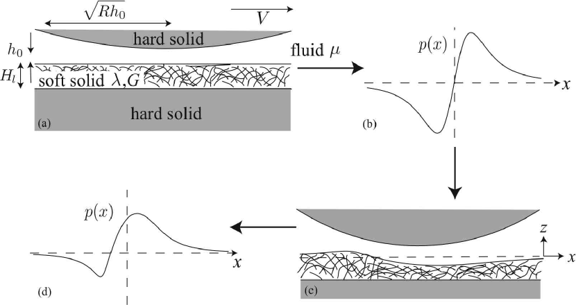
Continuing our analysis in the context of a cylinder moving along a planar wall, we take the direction to be parallel to the wall in the direction of motion of the cylinder and the direction to be perpendicular to the wall; is the fluid pressure; is the distance between the solid surfaces. Guided by lubrication theory Ba we use the following scalings
| (3) |
| (4) | |||
| (5) |
We consider steady motion in the reference frame of the cylinder, so that the boundary conditions are
| (6) |
Integrating (4,5,6) leads to the dimensionless Reynolds equation Re86 :
| (7) |
Since the gap pressure is much larger than the ambient pressure, we may approximate the boundary conditions on the pressure field as
| (8) |
Next, we consider the deformation of the elastic layer of thickness that rests on a rigid support. Balance of stresses in the solid leads to
| (9) |
with the stress given by
| (10) |
where is the displacement field and and are the Lamé constants for the solid, which is assumed to be isotropic and linearly elastic. To calculate the increase in gap thickness we use the analog of the lubrication approximation in the solid layer Jo85 . The length scale in the direction is and the length scale in the direction is . We take the thickness of the solid layer to be small compared to the thickness of the contact zone, , and consider a compressible elastic material, , to find the vertical force balance: The boundary condition at the solid-fluid interface is , so that . Using the zero displacement condition at the interface between the soft and rigid solid, leads to the following expression for the displacement of the surface
| (11) |
Then the dimensionless version of the gap thickness, , is
| (12) |
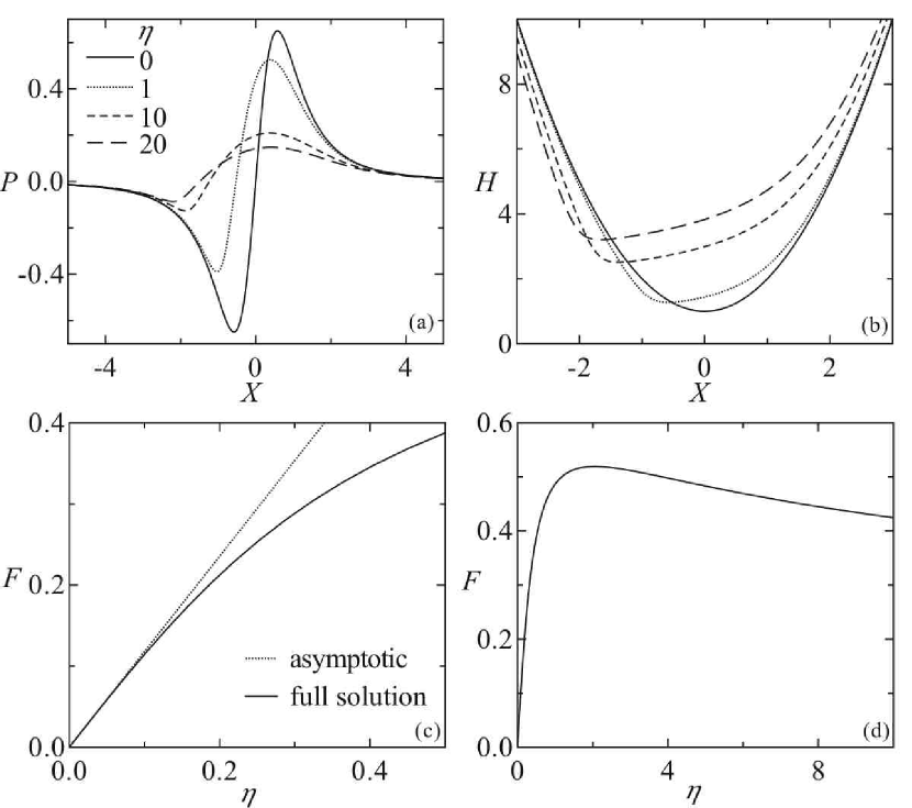
where is the dimensionless parameter governing the size of the deflection. Inspired by the some recent experiments MaCl02 in a similar geometry, we consider a cylinder of radius cm coated with a rubber layer ( cm, MPa) moving through water ( mPas, cm/s, cm). Then , so that we may use the perturbation expansion , where is the anti-symmetric pressure distribution corresponding to an undeformed layer, and is the symmetric pressure perturbation induced by elastic deformation. Substituting (12) into (7) leads to the following equations for :
| (13) | |||
| (14) |
subject to the boundary conditions . Solving (13) and (Soft lubrication) yields
| (15) |
Then the normal force is
| (16) |
In dimensional terms, whose scaling matches the result reported in SeLi93 , but with a different pre-factor. When is not small, we solve (7),(8) and (12) numerically. Figure 2 shows that as increases the mean gap increases and its profile becomes asymmetric, resembling the profile of a rigid slider bearing, a configuration well known to generate lift forces Ba . In addition, this increase in the gap size causes the peak pressure to decrease since . These two competing effects produce a maximum lift force when .
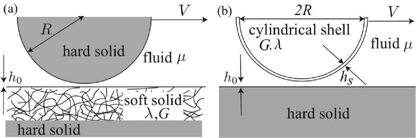
The physical basis for the previous arguments can be more easily understood using scaling and therefore allows us to generalize these results to a variety of configurations involving lubrication of soft contacts (Fig. 3; Table 1). Balancing the pressure gradient in the gap with the viscous stresses yields
| (17) |
Substituting , with , we find that the lubrication pressure is
| (18) |
Here does not contribute to the lift for the reasons outlined earlier, so that the the lift on the cylinder per unit length is
| (19) |
where is determined by the solution of the elasticity problem.
| Geometry | Material | Surface displacement | Lift force/unit length |
|---|---|---|---|
| Thin layer | Compressible elastic solid | ||
| Thin layer | Incompressible elastic solid | ||
| Thin layer | Poroelastic solid | ||
| Thick layer | Elastic solid | ||
| Cylindrical Shell | Elastic solid |
For a thin compressible layer, the case treated above, the normal strain is . Therefore,
| (20) |
In sharp contrast, a thin incompressible layer will deform via shear with an effective shear strain 333An incompressible solid must satisfy the continuity equation , which implies that .. Balancing the elastic energy with the work done by the pressure yields in terms of . Then, (17) and (19) give
| (21) |
A thick layer () may be treated as an elastic half space. The strain scales as and remains appreciable in a region of size . Balancing the elastic energy with the work done by the pressure yields in terms of . Then, (17) and (19) give
| (22) |
Finally, we consider the case of a cylindrical shell, of radius and thickness , moving over a rigid substrate. Since the shell is thin it can be easily deformed via cylindrical bending without stretching. The bending strain is so that the elastic energy . Balancing this with the work done by the pressure yields in terms of . Then, (17) and (19) give
| (23) |
We note that the above scalings for cylindrical contacts can be trivially generalized to spherical contacts for the case of small deformations, but space precludes us from discussing these in detail.
We conclude with a discussion of how our results may be applied to the lubrication of cartilaginous joints MoGu02 ; MoHo84 , where a thin layer of a fluid-filled gel, the cartilage, coats the stiff bones and mediates the contact between them. Here, electrostatic effects prevent physical contact of the surfaces under high static normal loads, while elastohydrodynamic effects could enhance separation and thus reduce wear. Inspired by the treatment of cartilage using poroelasticity Gr78 ; MoGu02 , the continuum description of a material composed of an elastic solid skeleton and an interstitial fluid Bi41 , we treat the cartilage layer as an isotropic poroelastic material 444We will ignore screened electrostatic effects to leading order in the elastohydrodynamic problem.. The gel can then be described by its fluid volume fraction , drained shear modulus and drained bulk modulus , thickness , permeability , and interstitial fluid viscosity . Using dimensional reasoning, we can construct a poroelastic time scale
| (24) |
which characterizes the time for the diffusion of stress over the layer thickness due to fluid flow. Then the response of the gel is governed by the relative size of to the time scale of the motion, . If , the motion is so slow that the interstitial fluid plays no role in supporting the load. If , the fluid supports some of the load transiently, thereby stiffening the gel. Finally, if the response of the gel will depend on the size of the Stokes’ length . If , there is no relative motion between the fluid and the solid and the gel behaves as an incompressible elastic solid SkMa04 ; BuKe81 , with shear modulus . From (20) and (21) we see that the effective modulus is
| (25) |
To find the scale of the deflection and lift force we use the same scaling analysis as for a thin compressible elastic layer but replace with , so that (20) yields
| (26) |
where . Inserting characteristic values cm/sec, g/sec2 cm, cm, cm, cm, cm3 sec/g shows that , but since significant material stiffening is prevented. Consequently, the effective modulus is and the scale of the deflection is
| (27) |
which suggests that joints could easily operate in a parameter regime that optimizes repulsive elastohydrodynamic effects. Although our estimates are based on non-conforming contact geometries; in real joints where conforming contacts are the norm, we expect a similar if not enhanced effect.
Acknowledgements.
We acknowledge support via the Norwegian Research Council (JS), the US Office of Naval Research Young Investigator Program (LM) and the US National Institutes of Health (LM) and the Schlumberger Chair Fund (L.M.). ∗Current address: Division of Engineering and Applied Sciences, Harvard University, 29 Oxford St., Cambridge, MA 02138. Email : lm@deas.harvard.eduReferences
- (1) Hamrock B.J. Fundamentals of fluid film lubrication McGraw-Hill, New York (1994).
- (2) Batchelor G.K. An introduction to fluid dynamics Cambridge University Press, Cambridge, UK (1967).
- (3) Reynolds O. Philos. Trans. R. Soc., London, Ser. A 177, 157 (1886).
- (4) Johnson K.L. Contact mechanics Cambridge University Press, Cambridge (1985).
- (5) Martin A., Clain J., Buguin A. & Brochard-Wyart F. Phys. Rev. E 65, 031605 (2002).
- (6) Sekimoto K. Liebler L. Europhys. Lett. 23, 113 (1993).
- (7) Mow V.C. Guo X.E. Annu. Rev. Biomed. Eng. 4, 175 (2002).
- (8) Mow V.C., Holmes M.H. & Lai W.M. J. Biomechanics 17, 377-394 (1984).
- (9) Grodzinsky A.J., Lipshitz H. & Glimcher M.J. Nature 275, 448-450 (1978).
- (10) Biot M.A. Journal of Applied Physics 12, 155 (1941).
- (11) Skotheim J.M. & Mahadevan L. Proc. R. Soc. Lond. (A) 460, 1995-2020 (2004).
- (12) Burridge R. & Keller J.B. J. Accoust. Soc. A. 70, 1140-1146 (1981).