Enhancement of the superconducting transition temperature in Nb/Permalloy bilayers by controlling the domain state of the ferromagnet.
Abstract
In (S/F) hybrids the suppression of superconductivity by the exchange field of the ferromagnet can be partially lifted when different directions of are sampled simultaneously by the Cooper pair. In F/S/F trilayer geometries where the magnetization directions of the two F-layers can be controlled separately, this leads to the so-called spin switch. Here we show that domain walls in a single F-layer yield a similar effect. We study the transport properties of Ni0.80Fe0.20/Nb bilayers structured in strips of different sizes. For large samples a clear enhancement of superconductivity takes place in the resistive transition, in the very narrow field range (order of 0.5 mT) where the magnetization of the Py layer switches and many domains are present. This effect is absent in microstructured samples. Comparison of domain wall width to the temperature dependent superconductor coherence length shows that , which means that the Cooper pairs sample a large range of different magnetization directions.
pacs:
74.45.+c,74.78.-w,85.25.HvProximity effects between a superconductor (S) and a ferromagnet (F) are the focus of
much current research, basically because of the possibilities for several distinct and
unusual phenomena. One is due to the fact the exchange field in the ferromagnet
gives rise to an oscillatory damped amplitude of the pairing function. In an S/F/S
geometry, this oscillation allows coupling of the superconducting banks with a phase
change of rather than 0 rado91 ; dem97 . This can be witnessed in a
nonmonotonic variation of the superconducting transition temperature as function of
the F-layer thickness tagir02 ; laz00 ; or, especially with a weak ferromagnet,
in the Josephson current of an S/F/S junction ryaz01 ; kontos02 or a superconducting
quantum interference device guich03 . Other phenomena are linked to a situation in
which the Cooper pair can sample different directions of within its coherent
volume. The best known example is an F/S/F geometry with a thin S-layer, in which the
magnetization of one F-layer can be rotated with respect to the other. The suppression of
the order parameter in S will then be larger when both magnetizations are parallel (P)
and smaller when they are antiparallel (AP). This so-called spin switch has been
discussed theoretically tagir99 ; buzdin99 and a first experimental realization was
recently reported by Gu et al. gu02 . They used a weak ferromagnet (CuNi) and
reported a small but measurable increase of with respect to (the
transition temperatures of the P and AP configurations, respectively) of about 5 mK.
However, the physics of the problem is more general. A weak ferromagnet is not an a
priori condition for the effect, and it might even be argued (although this has not been
emphasized in theoretical treatments) that ferromagnets with large exchange fields are
preferable. Also, the trilayer configuration is not the only one which can invoke
different directions for : any domain wall in the ferromagnet offers different
directions intrinsically, both in the wall and on either side. In claiming a coupling
effect between two F-layers, it might even be necessary to check the absence of in-plane
domain wall effects. Moreover, other mechanisms may be at play; inhomogeneous exchange
fields are predicted to induce enhanced superconductivity by spin-triplet excitations
kadi01 ; berge01 .
In this Letter, we investigate S/F bilayers and show that the domain state of a magnet
with strong spin polarization (Ni80Fe20, Permalloy (Py)) gives rise to an even
slightly larger increase in of the superconductor, in our case Nb, than mentioned
above. We give a qualitative discussion of the possible mechanism for the effect, which
is basically due to a lowered average exchange field seen by the Cooper pair and might
either be called an in-plane spin switch or domain wall induced -enhancement.
Samples of Nb/Py were prepared by sputter deposition in an ultrahigh vacuum system. They
were structured in simple bars of either 0.5 mm 4 mm (’large’ sample) or
1.5 m 20 m (’small’ sample). Contacts were not included in the
geometry in order to minimize problems with stray fields from contact pads or arms.
Instead, Au contacts for measuring in 4-point geometry were added by sputter deposition.
The choice of Py as ferromagnet is dictated by the wish for large (the spin
polarization is 45 % Mood98 ), but equally by the need of well-defined
magnetization switching at low fields. Since an easy axis for magnetization is induced by
the residual magnetic fields in the sputtering machine, care was taken to align the long
axis of the bars with the easy axis of magnetization êe. Magnetic fields were
applied in the plane of the sample, along the bars and therefore along êe.
Different layer thicknesses were used for both Nb and Py, which yielded similar results.
We will concentrate on samples with both the Nb and the Py thickness around 20 nm.
The zero-field resistance of a ’large’ sample of 21 nm Nb on 20 nm Py on a Si substrate
(denoted s/Py(20)/Nb(21)) as function of temperature is shown in Fig. 1. The
transition temperature is around 5.7 K, depressed from the pure Nb value by the proximity
of the F-layer. The width is about 100 mK.

After stabilizing the temperature at around 5.65 K, in the transition region, the magnetic field is swept from 65 mT down to -65 mT and back. The behavior of is shown in Fig. 2(c). From the positive field side at 15 mT, initially goes down, shows a small increase around 5 mT, but then goes down again, followed by a steep dip in a very small field regime around = -4.2 mT. Reversing the sweep from the negative field side, the behavior is symmetric, with a resistance dip now at +4.2 mT.
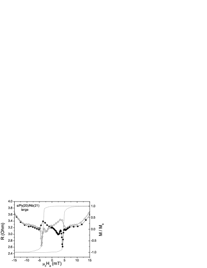
Also shown in Fig. 2 is the magnetization of the sample at 8 K, normalized by the saturation magnetization . The loop width is about 8 mT and the switch is quite sharp, although some rounding can be seen close to the coercive field which is due to the misalignment of the easy axis by a few degrees. It is clear that the deep dips in occur precisely at the switching field of the magnetic layer, which indicates that the domain state of the ferromagnet is involved, which is most prominent in the steep part of the magnetization reversal. Since the dip is very pronounced, we can also measure and compare this with in Fig. 1. We find that lies consistently below , with a maximum difference of about 10 mK. Several samples were measured which all show the same effect, and one data set for a sample s/Py(20)/Nb(19) (reversed Nb and Py) is shown in Fig. 3.
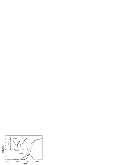
Again the deep dips in (inset in Fig. 3) are clearly present, but
there are differences in the details. For instance, is somewhat lower, around
4.85 K, presumably because Nb layer is slightly thinner. Also, the transition is sharper,
with a width of 50 mK. This necessitates a temperature stability during the field sweep
of better than 1 mK. The magnetization loop (not shown) is also wider, about 14 mT, and
the rise in before the dip is reached is higher as well. We believe both facts
may be due to the fact that the rotation of the magnetization in the covered Py-layer
proceeds slightly differently than in the free but probably oxidized Py-layer. Again,
lies consistently
below , with a smooth behavior of the difference.
The basic explanation we want to offer for our observations is that domain walls are
formed in the Py-layer during the switching of the magnetization, and that these domain
walls lead to the enhanced superconductivity. In order to argue this better, we performed
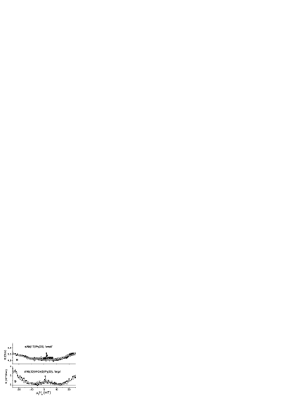
measurements on two other types of samples. Fig. 4(a,b) show data
(in the transition) on a ’small’ (1.5 m 20 m) sample
s/Nb(17)/Py(20) where no effect is found. The other is a ’large’ sample
s/Nb(20)/AlOx(8)/Py(20), where a thin Al layer was deposited and oxidized before the Py
layer was grown. No dips are found, but instead a small resistance increase is seen in
the field region of the Py loop, probably due to the effect of stray fields from the
magnetic layer on the superconducting layer. This shows that a proximity coupling is
necessary for the dips to
occur.
Before discussing the effects of domain walls on the superconductivity in more detail, it is necessary to address the characteristics of the walls. For the film thicknesses we use (around 20 nm), they are believed to be of Néel-type : the rotation of the magnetization occurs in the plane of the sample rather than out-of-plane (Bloch-wall), with the transition between the two at thicknesses around 40 nm o'hand00 ; kneller62 . We note that the magnetic flux coming out of a Bloch wall would suppress the superconductivity rather than do the opposite. The other important parameter is the width of the walls, which in Py is large due to the small magnetic anisotropy. For Bloch walls, is of the order of 0.5 m, for Néel walls and the case that it is of similar magnitude. A detailed study by scanning electron microscopy with polarization analysis on thick Py films with surface Néel walls yielded 0.25 m for the half-width of the walls scheinf91 . The fact that is much larger than the low-temperature coherence length of the superconductor (for our Nb, 12 nm) will come back in the discussion. The absence of an effect for the small samples s/Nb(17)/Py(20) can be explained by the fact that no stable domains were formed during switching of the magnetization direction. To confirm this assumption, we simulated the switching behavior for a range of Py structures with thickness 20 nm and different size and aspect ratio, using the OOMMFF code oommff . Values for the saturation magnetization and the magnetocrystalline anisotropy were determined from the magnetization measurements and taken to be = 860 [A/m] and = 500 [J/m3]. The easy axis direction was taken 6.5∘ away from the long axis of the structure in order to take the slight sample misalignment into account . Some pertinent results are shown in Fig. 5. In a structure with length and width of both 10 m, the magnetization loop is small and near the coercive field Hc (around 2 mT) stable domain configurations are present. Upon decreasing and increasing the aspect ratio , stable configurations no longer occur above = 2.5. For the 1 m 10 m structure, without a stable domain configuration, Hc has increased to 10 mT. Note that this is still below the value expected for a uniform rotation of the magnetization, which is of order according to the Stoner-Wohlfarth model o'hand00 , since domains are formed during the switching. The point is that they are not stable. Simulations on structures with larger length (above 50 m) showed stable multi-domain configurations near Hc even for structures with a 10. It is therefore the combination of small dimensions and large aspect ratio in our ’small’ samples which precludes stable domains.

The mechanism we believe to be responsible for the enhancement of the superconductivity
in the ’large’ samples is basically that the pair breaking experienced by a Cooper pair
is smaller when it samples different directions of the exchange field. In a sense, this
is the same mechanism as responsible for the F/S/F spin switch, but the simultaneous
sampling of two F-layers yields a different type of averaging. In order to estimate the
effect of the domain wall, we first consider the one-dimensional case of step-like
variation of which induces changes in the order parameter over a distance
(the coherence length in the F-layer) leading to a lowered pair breaking
parameter in the vicinity of the domain wall buzdin84 and superconductivity which
is enhanced with respect to the depression of the uniform F-layer. The situation
resembles -enhancement by twin planes khly87 ; abri88 and can be treated
accordingly. An estimate for the order of magnitude of the enhanced critical temperature
can be made as follows. The variation in pair breaking occurring over a distance
induces a superconducting order parameter over a distance around
the wall. In that case, the effective change in pair-breaking will be , and the -enhancement is correspondingly , with the critical temperature
due to the homogeneous suppression of the F-layer. Taking into account that
, we obtain . With 12 nm and for the strongly magnetic Py
1 nm, the effect is in the range of 1 %. The assumption of a step-like change
in is not correct, given the large value for , but it gives a feeling
for the orders of magnitude. For larger , the effect will increase as long as
, but for still larger it has to decrease to zero
again : the Cooper pair cannot sense the variation in any longer. In this limit,
the relative increase of is of order buzdin03 ,
which is again about 1 %. Another way of arguing that the experiment is sensitive to
domain wall formation comes from considering the temperature dependent (Ginzburg-Landau)
directly. Since we are measuring very close to , is actually much
larger than the low-temperature value. From a fluctuation analysis of we estimate
to be close to the top of the transition. In Fig. 3 it would be at
4.83 K, where the 0-field and in-field curves start to separate. With a typical
transition width of 30 mK, the relative temperature at the zero of resistance is , which makes about
0.15 m. In the transition, therefore, the condition is ,
and the Cooper pair samples a considerable part of the rotation of the magnetization.
This implies that in the case of Py the in-plane switch will only be visible close to
, since at lower temperature the magnetization is homogeneous on the scale of
. It is of interest to note that enhancement of critical currents below has
been reported for the case
of Nb/Co, where the domain walls are considerably smaller kinsey01
This work was supported by the ”Stichting FOM”. We thank A. Timofeev and S. Habraken for assistance in some of the experiments.
References
- (1) Z. Radovic, M. Ledvij, L. Dobrosavljevic-Grujic, A. I. Buzdin, and J. R. Clem, Phys. Rev. B. 44, 759 (1991).
- (2) E. A. Demler, G. B. Arnold,and M. R. Beasley, Phys. Rev. B. 55, 15174 (1997).
- (3) L. R. Tagirov. et al., J. Magn. magn. Mat. 240, 577 (2002).
- (4) L. Lazar, K. Westerholt, H. Zabel, L. R. Tagirov, Yu. V. Goryunov, N. N. Garifyanov and I. A. Garifullin, Phys. Rev. B 61, 3711 (2000).
- (5) V. V. Ryazanov et al., Phys. Rev. Lett. 86, 2427 (2001).
- (6) T. Kontos et al. Phys. Rev. Lett. 89, 137007 (2002).
- (7) W. Guichard et al. Phys. Rev. Lett. 90, 167001 (2003).
- (8) L. R. Tagirov, Phys. Rev. Lett. 83, 2058 (1999).
- (9) A. I. Buzdin, A. V. Vedyayev and N. V. Ryzhanova, Europhys. Lett. 48, 686 (1999).
- (10) J. Y. Gu et al., Phys. Rev. Lett. 89, 267001 (2002).
- (11) A. Kadigrobov, R. I. Shekter and M. Jonson, Europhys. Lett. 54, 394 (2001).
- (12) F. S. Bergeret, A. F. Volkov and K. B. Efetov, Phys. Rev. Lett. 86, 4096 (2001).
- (13) J. S. Moodera, J. Nowak and R. J. M. vandeVeerdonk, Phys. Rev. Lett. 80, 2941 (1998).
- (14) R. O’Handley, Modern Magnetic Materials, Wiley & Sons (2000).
- (15) E. Kneller, ’Ferromagnetismus’, Springer 1962.
- (16) M. R. Scheinfein et al., Phys. Rev. B 43, 3395 (1991).
- (17) M. Donahue and D. Porter, see URL http://math.nist.gov/oommff/.
- (18) A. I. Buzdin, L. N. Bulaevskii and S. V. Panyukov, Sov. Phys. JETP 60, 174 (1984).
- (19) I. N. Khlyustikov and A. I. Buzdin, Adv. in Physics 36, 271 (1987).
- (20) A. A. Abrikosov, ’Fundamentals of the theory of metals’, Chapter 20, p489, North-Holland, 1988.
- (21) A. I. Buzdin, unpublished result.
- (22) R. J. Kinsey, G. Burnell and M. G. Blamire, IEEE Trans. Appl. Superc. 11, 904 (2001).