Colloidal hard-rod fluids near geometrically structured substrates
Abstract
Density functional theory is used to study colloidal hard-rod fluids near an individual right-angled wedge or edge as well as near a hard wall which is periodically patterned with rectangular barriers. The Zwanzig model, in which the orientations of the rods are restricted to three orthogonal orientations but their positions can vary continuously, is analyzed by numerical minimization of the grand potential. Density and orientational order profiles, excess adsorptions, as well as surface and line tensions are determined. The calculations exhibit an enrichment [depletion] of rods lying parallel and close to the corner of the wedge [edge]. For the fluid near the geometrically patterned wall, complete wetting of the wall – isotropic liquid interface by a nematic film occurs as a two-stage process in which first the nematic phase fills the space between the barriers until an almost planar isotropic – nematic liquid interface has formed separating the higher-density nematic fluid in the space between the barriers from the lower-density isotropic bulk fluid. In the second stage a nematic film of diverging film thickness develops upon approaching bulk isotropic – nematic coexistence.
pacs:
61.30.Gd, 61.20.-p, 82.70.DdI Introduction
There is growing interest in properties of suspensions of colloidal particles near structured walls because of useful applications such as selective deposition of particles dins:98 and controlled growth of colloidal crystals yin:02 . While experimental dins:98 ; yin:02 , theoretical kino:02a ; kino:02b ; bryk:03 ; cast:03 , and computer simulation shoe:97 ; boda:99 ; dies:00 ; scho:02 studies have been devoted to the understanding of the behavior of spherical colloidal particles near geometrically structured substrates, suspensions of rodlike colloidal particles in contact with such substrates have not been investigated yet, despite the importance of rodlike colloids for both biological and materials application. From a theoretical point of view, as compared with fluids consisting of spherical particles the study of rods is more difficult because of the additional orientational degrees of freedom.
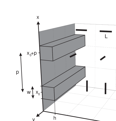
Here we study hard-rod fluids near geometrically structured walls within the Zwanzig approximation zwan:63 . In this model the allowed orientations of the rods are restricted to three mutually perpendicular orientations rather than a continuous range of orientations in space (see Fig. 1); the positions of the rod centers are continuous variables. The advantage of this model is that the difficult determination of spatially inhomogeneous density and orientational order profiles becomes feasible allowing one to study various aspects of hard-rod fluids near structured walls in detail. On the basis of recent theoretical studies on fluids of hard rods near planar hard walls roij:00 ; roij:00a ; harn:02c , we expect to find results which remain qualitatively correct even in the absence of the restriction to discrete orientational directions. In Sec. II we describe the density functional theory which is used to analyze a hard-rod fluid in contact with an individual right-angled wedge or edge (Sec. III) or with a periodically patterned wall (Sec. IV).
II Model and density functional theory
We consider an inhomogeneous fluid consisting of hard rods of length and diameter . The number density of the centers of mass of the rods at point with orientation of the normal along their main axis of symmetry is denoted as . The equilibrium density profile of the inhomogeneous liquid under the influence of an external field minimizes the grand potential functional
where is the thermal de Broglie wavelength and is the chemical potential. Within the Onsager second virial approximation the free energy functional in excess of the ideal gas contribution reads onsa:49
| (2) | |||||
where is the Mayer function of the interaction potential between two rods. The Mayer function equals if the rods overlap and is zero otherwise.
In the present application of density functional theory we concentrate on the ordering effects induced by surfaces geometrically structured such that the resulting depends on two spatial coordinates. For the model system displayed in Fig. 1, apart from the possibility of surface freezing at high densities, non-uniformities of the density occur only in the - plane, so that . Minimization of with respect to leads to the following Euler-Langrange equation:
| (3) |
This equation can be solved numerically for a given chemical potential and a given external field . For computational purposes, the density profile has to be specified on a sufficiently fine four-dimensional grid. In order to reduce this computational effort we use the Zwanzig model for rods zwan:63 . Within the Zwanzig model the rods are represented by rectangular blocks of size . The positions of the center of mass vary continuously, while the allowed orientations of the normal of each rod are restricted to directions parallel to the , , and axis (see Fig. 1). Using the notation , , and with , the Euler-Langrange equations for a fluid consisting of thin Zwanzig rods () can be written as
| (4) | |||||
| (5) | |||||
and
| (6) | |||||
which allow for a straightforward iterative numerical computation on a two-dimensional grid. We note that the meaning of the terms on the right side of Eqs. (4)-(6) can easily be inferred from considering the various orientations of the rods (see Fig. 1). It is convenient to introduce the variable . In the following sections numerical data are given in terms of and we drop the star in order to avoid a clumsy notation.
The bulk phase behavior of this model was studied a long time ago by Zwanzig zwan:63 , who found a first-order isotropic – nematic phase transition similar to Onsager’s result for freely rotating rods onsa:49 . Recently, the Zwanzig model has been used to investigate the phase behavior of monodisperse roij:00 ; roij:00a and binary harn:02c rod fluids near a single planar hard wall and confined in slit pore. These calculations yield a wall-induced continuous surface transition from uniaxial to biaxial symmetry. Complete wetting of the wall – isotropic liquid interface by a biaxial nematic film has been found. For the fluids confined by two parallel hard walls, at large slit widths a first-order capillary nematization transition occurs, which terminates in a capillary critical point upon decreasing the slit width.
III Hard-rod fluid near a right-angled wedge and edge
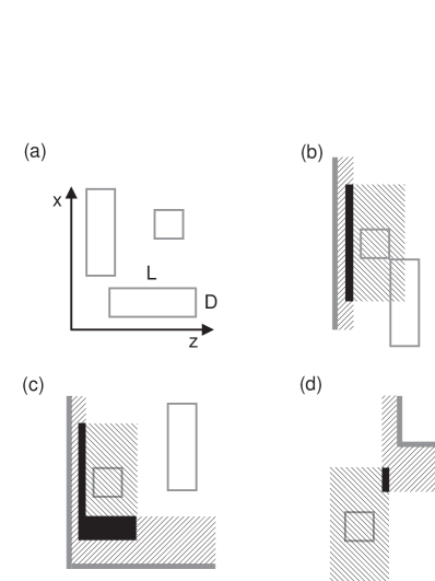
Before studying the hard-rod fluid near the geometrically structured surface shown in Fig. 1 it is instructive to analyze first the fluid around an individual right-angled wedge or edge (see Fig. 2).
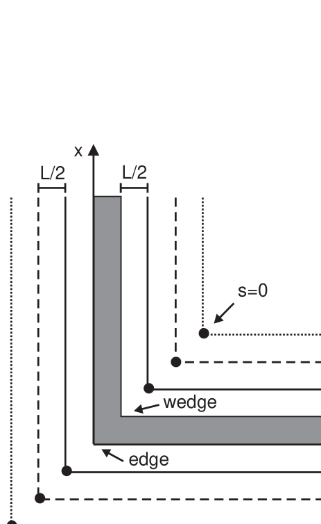
These simple geometrical structures constitute the building blocks of the structured surface displayed in Fig. 1. An analysis of the size dependence leads to the following decomposition of the grand canonical potential functional of the fluid which in its bulk is taken to be in the isotropic phase:
| (7) |
where is the bulk grand canonical potential density, is the wall – isotropic liquid surface tension at a planar wall and is the line tension of the isotropic liquid with for the wedge and for the edge. The extension of the system in direction is defined as the length available to the rim of the particles at closest approach to the boundary.
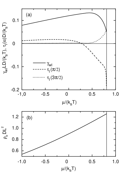
We restrict our analysis to chemical potentials smaller than the chemical potential at bulk isotropic – nematic coexistence. Figure 3 displays the surface tension as well as the line tensions and as a function of the chemical potential. The steric interaction between the particles increases the surface tension with increasing chemical potential. On the other hand, the onset of the surface-induced nematic ordering of the particles leads to a decrease of the surface tension for larger chemical potentials. In the limit of large negative chemical potentials, i.e., for non-interacting particles, the wall – isotropic liquid surface tension as well as the line tensions vanish. The line tension for the fluid near a right-angled wedge exhibits a change of sign with increasing chemical potential while for all values of . We note that by construction . As a function of the line tension corresponds to the work done per unit length, against the fluid, to change the dihedral angle from to some value hend:02 ; hend:04 . The corresponding solvation torque is .
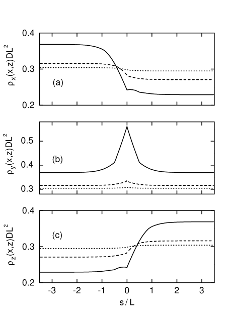
Figures 4 and 5 show the density profiles at the right-angled wedge and edge for a chemical potential . The profiles are evaluated along lines parallel to the confining walls (see Fig. 2), using a linear parametrization such that corresponds to the position of the corner. For the density profiles at a planar hard wall are recovered. As is apparent from Fig. 4 the density profile exhibits a maximum at for the right-angled wedge. This maximum increases upon approaching the corner of the wedge. For a right-angled edge a significant depletion of rods lying parallel to the axis is found near the corner (see Fig. 5). The sharp features of the density profiles in the presence of the right-angled edge are caused by the vanishing of and which is due to the presence of the impenetrably hard walls.
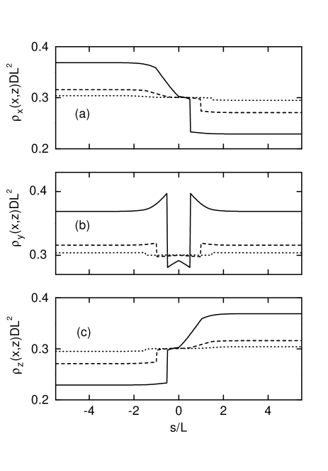
Such cusps and discontinuities – although less pronounced – have already been found for the density profiles near a planar hard wall using the Zwanzig model roij:00 ; roij:00a ; harn:02c , while the interfacial profiles between demixed fluid phases, as calculated for the same model, exhibit neither cusps nor discontinuities bier:04 . We do not expect to observe discontinuities in the density profiles for freely rotating rods near an edge, similar to our findings for hard rods near a planar hard wall harn:02a (see discussion below). Although the calculated density profiles presented in Figs. 4 and 5 can only be considered to be of qualitative significance we expect that the main features, namely the enrichment [depletion] of rods lying parallel and close to the corner of a wedge [edge] as well as the asymmetry of the density profiles and with respect to the line , remain valid for freely rotating rods.
In order to understand the structure of the density profiles displayed in Fig. 4 and 5, it is instructive to apply the idea of entropically driven forces (see, e.g., Ref. roth:00 ) to the Zwanzig model. We consider rods of a given orientation along the x, y, and z axis as belonging to one of three ”species”. Such a three-component fluid maximizes its entropy by maximizing the volume accessible per rod. Although there exist only steric repulsions between pairs of particles, maximizing the entropy in the fluid mixture can lead to an effective entropic attraction between the rods and the walls. Figure 6 (b) demonstrates that, when a rod of a given species approaches a planar wall (represented in grey), the total volume available to rods of the other species increases. This increases the total entropy of the mixture by an amount proportional to the size of the excluded-volume overlap region (represented in black) multiplied by the pressure. For a rod lying close and parallel to a right-angled wedge [edge] the corresponding excluded-volume overlap region is increased [decreased] (see Figs. 6 (c) and (d), respectively) leading to an enrichment [depletion] of such rods close to the corner of a wedge [edge]. The results may be interpreted in terms of a repulsive barrier of an effective potential repelling a rod, which is oriented parallel to the corner of an edge, approaching the edge from the side and practically preventing it from passing around the corner. On the other hand the effective potential acting on a rod which is oriented parallel to the corner of a wedge is ”pushing” it into the corner. For a detailed analysis of these mechanisms acting on mixtures of hard spheres near edges and wedges see Ref. bryk:03 and in particular Figs. 5 - 7 therein.
The simple illustration in Fig. 6 (d) is also helpful for understanding the aforementioned discontinuities in the density profiles near the right-angled edge (see Fig. 5). When a thin rod (), which is oriented parallel to the edge, approaches the edge from the side, the excluded-volume overlap drops abruptly to zero before the rod is passing around the corner. This causes the discontinuities in the density profiles along the paths specified in Fig. 2. For freely rotating rods the corresponding excluded-volume overlap decreases smoothly to zero because of the huge number of differently oriented rods acting on the rod which is oriented parallel to the edge.
Finally, we briefly discuss the phase behavior of hard rods confined in a hard pore of square cross-section. The immediate consequence of the pore is that rods oriented perpendicular to the confining walls cannot approach closer than a center-of-mass distance . There is a pronounced increase of the density of rods orientated parallel to the main axis of the pore in the corners of the pore because of the aforementioned effective entropic attraction.
For sufficiently large cross-sections of the pore, we observe coexistence between an isotropic phase and a capillary condensed nematic phase. The density profile of the capillary condensed nematic phase is characterized by a nematic phase throughout the pore, whereas the density profile of the coexisting phase decays toward an isotropic phase in the middle of the pore. For small pore cross-sections a sharp capillary nematization transition no longer occurs and is replaced by a steep but continuous filling upon increasing the chemical potential. For the same fluid confined in a slit pore the confinement effects are weaker. Thus, in the slit pore we observe capillary nematization at a higher chemical potential corresponding to a higher particle number density of the bulk fluid. However, the spatially averaged particle number density of the coexisting inhomogeneous isotropic phase in the slit pore is smaller than the corresponding one in the pore of square cross-section.
IV Hard-rod fluid in contact with a periodically structured hard wall
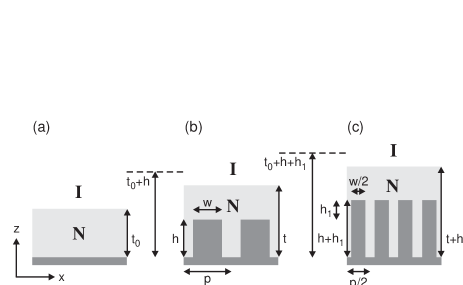
We now turn our attention to the properties of the hard-rod fluid in contact with the hard wall shown in Fig. 1. The surface of the wall is periodically patterned with rectangular hard barriers of width and height , where the periodicity is denoted by . We focus on the numerically determined orientationally averaged number density profile
| (8) |
and the excess adsorption defined as
| (9) |
where is the total particle number density of the homogeneous bulk fluid. The volume of the system is defined as the total volume of the container, i.e., the left boundary of the system displayed in Fig. 1 is taken to be the surface of the substrate wall which implies that the trenches between the barriers contribute to . Figure 7 displays for various values of the barrier height and two values of the barrier width at a fixed periodicity of the surface pattern. For non-interacting rods (), the calculated excess adsorption reveals a slight depletion close to the surface () because there is less space available to the rods in the presence of the impenetrably hard walls. For the same reason this depletion becomes more pronounced with increasing height of the barriers (i.e., increasing the actual exposed solid area). Upon increasing the chemical potential, the excess adsorption increases and exhibits a change of sign because of the aforementioned entropic attraction between the rods and the surface [see Fig. 6]. For small barrier heights, increases smoothly upon increasing the chemical potential, while a pronounced variation of the excess adsorption is found for large barrier heights at a chemical potential smaller than the chemical potential at bulk isotropic – nematic coexistence. Moreover, the calculation renders to diverge logarithmically as . Near the excess adsorption can be fitted by , with fit parameters and , where turns out to be independent of the surface pattern.
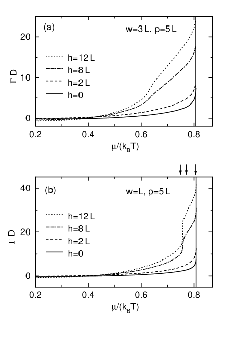
The logarithmic divergence of is consistent with complete wetting of the wall - isotropic fluid interface by a nematic film in the absence of algebraically interaction potentials diet:88 . A similar behavior of the excess adsorption close to has been found for the same fluid near a planar hard wall roij:00 ; roij:00a ; harn:02c .
To understand the origin of the calculated excess adsorptions, it is instructive to study the variation of the density profiles with increasing chemical potential. The orientationally averaged density profiles shown in Fig. 8 demonstrate that the wetting of the non-planar wall – isotropic liquid interface by a higher-density nematic film occurs as a two-stage process where first the nematic phase fills the space between the barriers until an almost planar isotropic – nematic liquid interface has formed separating the higher-density nematic fluid in the space between the barriers from the lower-density isotropic bulk fluid. In the second stage a nematic film of diverging film thickness develops upon approaching the chemical potential at bulk isotropic – nematic coexistence. In the presence of the patterned wall, the director (the average orientation of the rods) of the nematic phase is parallel to the -axis because of the aforementioned effective entropic attraction between rods oriented parallel to the right-angled wedges of the barriers [see Fig. 6 (c)].

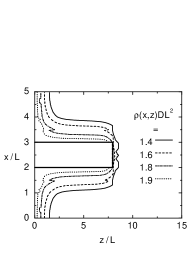
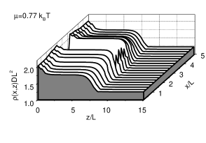
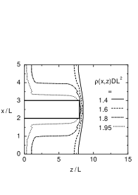
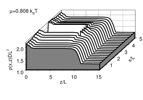
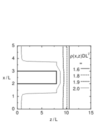
Upon approaching the chemical potential at bulk isotropic – nematic coexistence, i.e., in Fig. 7 (with this value of the kink position being largely independent of ), the calculated density profiles at the isotropic – nematic interface become virtually indistinguishable from the free isotropic – nematic interface between coexisting bulk phases, as expected for the case of complete wetting. In this limit this holds irrespective of the actual values of the width , height , and periodicity . However, the thickness of the emerging nematic film depends on the aforementioned model parameters and the chemical potential.
A very thin nematic liquid layer – corresponding to a large undersaturation – follows the substrate pattern, whereas a sufficiently thick layer is essentially flat (see Fig. 8). In the following, we will be exclusively concerned with thick nematic films, allowing us to define an -independent film thickness defined as the distance between the midpoint of the density profile for the planar isotropic – nematic interface and the substrate surface ; is a scaling function appearing on the basis of dimensional analysis. The minimal film thickness for which a planar isotropic – nematic liquid interface is still possible is . We consider the situation as illustrated in Fig. 9 (a), where for a given chemical potential a nematic (N) film of thickness intrudes between a planar hard wall and an isotropic (I) bulk fluid. At the same chemical potential the film thickness of the fluid in contact with a geometrically patterned wall is larger than the height of the barriers and smaller than (see Fig. 9 (b)). For it follows that as expected on physical grounds. It is worthwhile to mention that as function of for given , , and exhibits a discontinuity upon approaching because the ratio of the actual substrate area (including the side planes of the rectangular blocks) per period over the one projected onto the plane drops abruptly from to for . Hence, due to geometric constraints the film thickness in the presence of infinitely thin barriers differs from the one in the absence of the barriers. Moreover, we find the following properties, which are schematically visualized in Figs. 9 (b) and (c):
| (10) |
and for fixed and
| (11) |
Equation (10) states that upon varying the barrier width and the periodicity such that the ratio of the substrate area at the bottom over the substrate area at the top is kept fixed, the film thickness does not change for a given barrier height , chemical potential , and . This result is reminiscent of the Cassie equation cass:48 . Cassie considered a simple liquid in contact with a smooth but chemically striped surface with periodicity such that on stripes of width one has a contact angle and in between . The apparent average contact angle is given by
| (12) |
Since , , and are determined uniquely by , , and via the corresponding effective interface potentials (see Eq. (4.56) in Ref. diet:88 ), Eq. (12) states that the apparent film thickness depends only on the ratio , which is the analogue of Eq. (10).
Whereas Eq. (10) is valid for all values of , , and , for molecular-scale surface patterns with barrier heights we find deviations from Eq. (11).
The wetting of the non-planar wall – isotropic liquid interface by a nematic film is driven by the steric interaction of the rods with the solid substrate which is mediated by the fluid occupying the space between the barriers. As the barrier height increases the interaction between rods located at and the part of wall which is located at weakens, such that for large height and small width , wetting is dominated by the interaction with the fluid in the space between the barriers and not by that with the solid substrate at . However, one has to take into account that the rods in the trenches between the barriers interact not only with the part of the substrate wall which is located at but also with the side planes of the rectangular blocks which are parallel to the plane.
V summary
We have studied hard-rod fluids near geometrically structured walls using Zwanzig’s model of square parallelepipeds with only three allowed orientations (Fig. 1). Within the framework of a density functional theory, the grand potential functional is minimized numerically and density profiles, excess adsorptions as well as surface and line tensions are determined leading to the following main results:
(1) The line tension for the isotropic fluid in contact with a right-angled wedge (see Fig. 2) exhibits a change of sign with increasing chemical potential while the line tension for the fluid in contact with a right-angled edge as well as the wall – isotropic fluid surface tension at a planar hard wall are positive (Fig. 3).
(2) Figures 4 and 5 demonstrate an enrichment [depletion] of rods lying parallel and close to the corner of a right-angled wedge [edge]. On the basis of effective entropic forces between the rods and the walls (see Fig. 6), the results may be interpreted in terms of a repulsive barrier of an effective potential repelling a rod, which is oriented parallel to the corner of an edge, and approaches the edge sidewise, and practically preventing it from passing around the corner. The effective potential acting on a rod which is oriented parallel to the corner of a wedge is larger than the one close to a planar wall. Building on the effects demonstrated in Figs. 4, 5, and 6, it seems possible to devise structures that create localized and directional entropic force fields for both natural and synthetic rodlike colloids.
(3) Coexistence between an isotropic and a capillary condensed nematic phase is observed for the fluid confined in a hard pore of square cross-section, provided the cross-section is sufficiently large. The density profile of the capillary condensed nematic phase is characterized by a nematic phase throughout the pore, whereas the density profile of the coexisting phase decays towards an isotropic phase in the middle of the pore. For the same fluid confined in a slit pore the confinement effects are weaker, i.e., in the slit pore one observes capillary nematization only at a higher chemical potential.
(4) From the calculated excess adsorptions (Fig. 7) and density profiles (Fig. 8) of a fluid consisting of hard rods near the geometrically structured wall shown in Fig. 1, we conclude that complete wetting of the non-planar wall – isotropic liquid interface by a nematic film occurs as a two-stage process. In the first stage the nematic phase fills the space between the barriers until an almost planar isotropic – nematic liquid interface has formed separating the higher-density nematic fluid in the trenches between the barriers from the lower-density isotropic bulk fluid. In the second stage a nematic film of diverging film thickness develops upon approaching the chemical potential at bulk isotropic – nematic coexistence. The film thickness, defined as the distance between the midpoint of the density profile for the almost planar isotropic – nematic interface and the substrate bottom at , is larger for the fluid near the geometrically structured wall than the one for the fluid near a planar wall at the same chemical potential (Fig. 9).
Finally, we note that phenomena which emerge from the contact of a rod fluid which is in its bulk in the nematic phase are also interesting because of the possibility to deliver external lateral structures deep into the bulk of the adjacent fluid which offers a convenient means to image patterned surfaces. Density functional theory will allow one to study also such a system.
References
- (1) A. D. Dinsmore, A. G. Yodh, and D. J. Pine, Nature 383, 239 (1996).
- (2) Y. Yin and Y. Xia, Adv. Mater. 14, 605 (2002).
- (3) M. Kinoshita and T. Oguni, Chem. Phys. Lett. 351, 79 (2002).
- (4) M. Kinoshita, J. Chem. Phys. 116, 3493 (2002).
- (5) P. Bryk, R. Roth, M. Schoen, and S. Dietrich, Europhys. Lett 63, 233 (2003).
- (6) R. Castaneda-Priego, A. Rodriguez-Lopez, and J. M. Mendez-Alcaraz, J. Phys.: Condens. Mat. 15, 3393 (2003).
- (7) M. Schoen and S. Dietrich, Phys. Rev. E 56, 499 (1997).
- (8) D. Boda, K.-Y. Chan, D. Henderson, D. T. Wasan, and A. D. Nikolov, Langmuir 15, 4311 (1999).
- (9) D. J. Diestler and M. Schoen, Phys. Rev. E. 62, 6615 (2000).
- (10) M. Schoen, Colloids Surf. A. 206, 253 (2002).
- (11) R. Zwanzig, J. Chem. Phys. 39, 1714 (1963).
- (12) R. van Roij, M. Dijkstra, and R. Evans, Europhys. Lett. 49, 350 (2000)
- (13) R. van Roij, M. Dijkstra, and R. Evans, J. Chem. Phys. 113, 7689 (2000).
- (14) L. Harnau and S. Dietrich, Phys. Rev. E. 66, 051702 (2002).
- (15) L. Onsager, Phys. Rev. 62, 558 (1942); L. Onsager, Ann. (N.Y.) Acad. Sci. 51, 627 (1949).
- (16) J. R. Henderson, Physica A 305, 381 (2002).
- (17) J. R. Henderson, J. Chem. Phys. 120, 1535 (2004).
- (18) M. Bier, L. Harnau, and S. Dietrich, Phys. Rev. E. 69, 021506 (2004).
- (19) L. Harnau and S. Dietrich, Phys. Rev. E. 65, 021505 (2002).
- (20) R. Roth, R. Evans, and S. Dietrich, Phys. Rev. E 62, 5360 (2000).
- (21) S. Dietrich, in Phase Transitions and Critical Phenomena, edited by C. Domb and J. L. Lebowitz (Academic, London, 1988), Vol. 12, p. 1.
- (22) A. B. D. Cassie, Discuss. Faraday Soc. 3, 11 (1948).