Velocity Fluctuations in Dynamical Fracture: the Role of Microcracks
Version of
Abstract
We address the velocity fluctuations of fastly moving cracks in stressed materials. One possible mechanism for such fluctuations is the interaction of the main crack with micro cracks (irrespective whether these are existing material defects or they form during the crack evolution). We analyze carefully the dynamics (in 2 space dimensions) of one macro and one micro crack, and demonstrate that their interaction results in a large and rapid velocity fluctuation, in qualitative correspondence with typical velocity fluctuations observed in experiments. In developing the theory of the dynamical interaction we invoke an approximation that affords a reduction in mathematical complexity to a simple set of ordinary differential equations for the positions of the cracks tips; we propose that this kind of approximation has a range of usefulness that exceeds the present context.
I Introduction
Classical linear elasticity fracture mechanics provides clear cut predictions for the dynamical evolution of cracks in stressed materials. Under pure mode I loading a crack is expected to remain straight, and to exhibit a tip velocity that increases monotonically towards the Rayleigh wave speed . Reality shows that this is but a pipe dream. When the crack velocity exceeds a finite fraction of the velocity of typical cracks exhibits wild fluctuations, the crack surfaces lose their smoothness and the mean velocity never asymptotes towards . The fundamental understanding of the discrepancy between the prediction of the classical theory and experiments remains an open problem of considerable interest and importance.
A number of studies 84R-CK_1 ; 84R-CK_2 ; 95SF ; 96SF ; 97R-CY ; 98R ; 99SF ; 99FM point towards a close correspondence between the onset of velocity fluctuations and the appearance of secondary damage like micro cracks (appearing ahead of the tip), microscopic side branches etc. Conical markings which are observed on crack surfaces offer a good indication that micro cracks exist before the arrival of the crack, although it is not determined whether the former stem from material imperfections or from stress instabilities. The fact that the density of conical markings increases during the crack evolution 97R-CY suggests that the level of stress is responsible in some way for the activation of the micro cracks. The aim of this paper is to explore the connection between velocity fluctuations and the putative existence of micro cracks ahead of the crack tip. To this aim will study the dynamical interaction between a macro crack and a micro crack and focus on the velocity of the tip of former under the influence of the latter.
To actually solve exactly the dynamical equations for the displacement field with boundary condition on both macro and micro cracks up to coalescence is a very taxing quest. Building upon experience in the field we will propose here an approximate methodology that will allow us writing down ordinary differential equations for the positions of the tips of both macro and micro cracks. While sensible, the approximate methodology is not established in a controlled fashion, requiring therefore simulational support. Indeed, we will offer in this paper lattice simulations to back the analytic considerations. We will show that the correspondence is excellent.
In Sect. II we introduce the problem at hand, being an infinite 2-dimensional stressed material with one macro crack and one colinear micro crack of length . In Sect. III we describe the approximate method of solution, motivating it by the exactly soluble cases of straight and bifurcating cracks. The Section culminates with approximate equations of motion for the tips of the macro and micro cracks. In Sect. IV we describe the solution of the model problem, stressing the velocity of the tip of the macro crack. We show that the net result of the interaction is a rapid and large up and down fluctuation in this velocity, in correspondence with the observed fluctuations in dynamical crack propagation. Sect. V provides a simulational support to the approximate theory; by performing lattice simulations we study the same model problem and compare the results. The close correspondence between approximate theory and simulations lends support to the former. Sect. VI offers a summary and conclusions.
II The problem
The problem that we want to consider is sketched in Fig.
1. We consider a macro crack and a micro crack that
at a given time extend along the intervals and
respectively. The distance between them is given by . The
length of the micro crack is . We
expect on physical grounds that the micro cracks in typical
materials are at most of the size of the process zone, and
therefore we always consider the limit .

The aim of the calculation is to determine the simultaneous motion of the three crack tips (the macro crack tip, the inner and outer tips of the micro crack) as a function of time. In full generality this entails the general solution of the field equations for an arbitrary motion, specifically the determination of the dynamic stress intensity factors at the cracks tips and then to apply a fracture criterion to obtain the actual dynamics. We cannot offer an exact solution to this problem. Instead, we will introduce an approximate method that provides analytic insight to the problem.
III Approximate method of solution
To motivate our approximate methodology we will recall some exact classical results obtained for ideal (mode I) straight dynamical cracks and more recent results pertaining to (mode III) bifurcating cracks.
III.1 Motivation I: Ideal Straight Cracks
As said above, linear elasticity fracture mechanics provides exact solutions for straight cracks under mode I loading. The stress field , measured in polar coordinates relative to the tip, is expected to have a universal form in the vicinity of the crack tip 98F ,
| (1) |
Here and are the time-dependent crack velocity and length respectively, are known universal functions 98F , and is the “stress intensity factor” which is predicted to depend on the instantaneous crack velocity and length only. For notational simplicity we drop the dependence. At each moment in time the velocity is expected (for plane stress conditions) to be determined by the energy balance equation 98F
| (2) |
The LHS here is the fracture energy and the RHS is the energy release rate into the crack tip region, resulting from a path integral over the total energy flux. is Young’s modulus and is a mode I universal function. The exact result that we refer to is the decomposition of the dynamic stress intensity factor for a semi-infinite crack under time independent loading, in the form 98F ; 72F ; 75Kos
| (3) |
where is a universal function of and is the stress intensity factor of a static crack of length under the same loading (when is large enough to be considered as semi-infinite). This important result is the basis of the classical theory of straight crack motion. The calculation of the static stress intensity factor is a much easier task than the evaluation of its dynamical counterpart, since it requires solutions of bi-Laplace equations with boundary conditions. Rewriting Eq. (2) in the light of this result one obtains,
| (4) |
A further serendipitous simplification arises from numerical evaluations of the combination , showing that it is well approximated by 98F
| (5) |
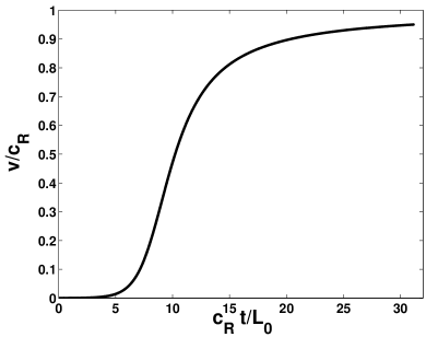
This approximation leads to an ordinary differential equation for the crack length. If one asserts that the fracture energy is -independent this differential equation becomes explicit,
| (6) |
It should be stressed again that the decomposition property of the dynamic stress intensity factor (Eq. (3)) is essential in deriving this basic equation. This equation predicts a monotonic increase in the tip velocity asymptoting towards . There is no crack motion as long as the stress intensity factor does not exceed a material dependent threshold
| (7) |
For the sake of illustration we show in Fig. 2 the solution of this equation for the simple case , where is the load at infinity.
III.2 Motivation II: Bifurcating Cracks
The bifurcation of fast cracks is observed in many experiments, and understanding it theoretically is a problem of some importance in the theory of fracture. One interesting problem that was addressed recently 03A-B in this context is the determination of the stress intensity factors at the tips of symmetrically branched cracks in terms of the stress intensity factor prior to branching. Ref. 03A-B presented a solution to this problem for mode III (anti-plane) conditions. In this solution the stress intensity factor at the tips of two symmetric branches emerging from a macro crack at a velocity and creating an angle relative to the macro crack line, was given in the form
| (8) |
Here is the mode III universal function, whose mode I counterpart is , is the shear wave speed, is the stress intensity factor of the macro crack prior to branching and carries the information regarding the dynamic interaction. Note that the macro crack velocity is absent here as in the branching scenario adopted in 03A-B the macro crack stops suddenly before branching and a static stress distribution is established behind a wave front travelling at the characteristic wave speed . If the decomposition in Eq. (3) is of some generality then we expect the main interaction effect to be contained in the static stress intensity factors for the bifurcated configuration given by . Indeed, Fig. 4 in ref. 03A-B shows that ratio
| (9) |
is very close to unity (up to ) for all the values of and . Therefore, we conclude that even for this complex configuration the dynamic stress intensity factor admits an approximate decomposition in the form of a product of its static counterpart and a universal function of the local crack tip velocity,
| (10) |
This result suggests that a very good approximation for the dynamic stress intensity factor can be obtained by calculating the static stress intensity factor for the same instantaneous configuration and a knowledge of a universal velocity function characteristic of the local symmetry conditions at the crack tip.
III.3 The Decomposition Approximation for our Problem
For advancing the problem posed in this paper we need to consider the stress field in the vicinity of three crack tips. In the vicinity of the tip of the macro crack we write (in the local polar coordinates around that tip)
| (11) |
where is the stress intensity factor that in principle depends on the positions and velocities of all the tips [i.e. ] and maybe other derivatives. Near the tips of the micro crack we write similarly (in local polar coordinates around each tip)
| (12) |
where are again the stress intensity factors that depend on all the time dependent functions and maybe other derivatives.
Our basic approximation is now motivated by the two examples Eqs. (3) and (10); we assume that the dynamic stress intensity factors can be decomposed according to
| (13) |
Here the universal function is the same function appearing in Eq. (3) and all the stress intensity factors with superscript refer to the solution of the static problem with a frozen geometry which is given by the crack tip positions . On physical grounds we expect this approximation to be good when , and to lose its validity as this ratio increases. The numerical simulations presented in Sect. V lend a strong support to this expectation.
IV Solution of the model
IV.1 The static problem
A prerequisite to the solution of the set of equations (14) is the calculation of the static stress intensity factors for a general configuration of two colinear cracks. We employ the available solution for two colinear cracks consisting of segments and with under a remote mode I loading . The component of the stress tensor along the cracks line, outside the cracks, is given by 99B
| (15) | |||||
Here
| (16) |
and and are the complete elliptic integrals of the first and second kind bluebook . The stress intensity factor at any one of the tips is obtained by taking the limit
| (17) |
where is any one of positions of the tips.
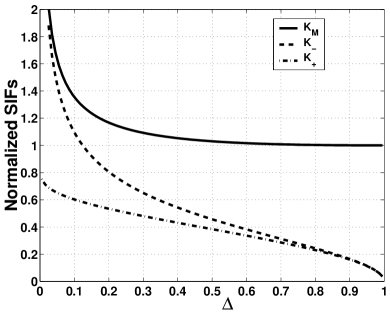
In order to adapt the general configuration to our macro crack and micro crack configuration we set , , , . Taking the limits in Eq. (17), under the assumption , we can extract the stress intensity factors at the three tips
| (18) | |||||
Note that the common pre-factor is just the stress intensity factor of the macro crack in the absence of the micro crack and serves here as the scale of the three stress intensity factors. In Fig. 3 we present the three stress intensity factors as a function of . In this example we kept the macro tip at and the right micro tip at fixed while was changed. We note that the stress intensity factor of the macro crack goes to the single crack result (unity in the reduced coordinates of Fig. 3) when . Similarly, the stress intensity factor at goes to unity when , since also in that limit we remain with one crack. This last fact is not easily seen in Fig. 3 since the upturn towards unity is very rapid, occurring just before coalescence.
IV.2 The dynamic problem
Using the static stress intensity factors Eqs. (18) in Eqs. (14) we can solve numerically for the dynamics of the three tip positions. An example of the ensuing dynamics is exhibited in Fig. 4.
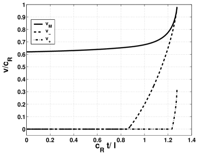
We note that what is seen in this picture is typical to all the conditions that we have considered: the macro crack is first accelerated, then the left tip of the micro crack meets the fracture criterion Eq. (7) and accelerates towards the macro crack; after some time lag, the right tip meets the fracture criterion and starts to move and attains at coalescence a lower velocity than the original macro crack.
To connect to velocity fluctuations observed in experiment we reinterpret the data in Fig. 4 as it would be seen by an observer. We are physically motivated by the fact that as a result of a finite measurement resolution, below a critical separation the macro crack tip and the outer tip of the micro crack are indistinguishable and the measured velocity is a result of some averaging. Therefore, let us define the experimental velocity as
| (19) |
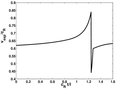
Figure 5 shows the experimental velocity during an interaction event. The rise in velocity after the steep decline is the second of Eqs. (19). The last branch in which the velocity returns to the pre-collision value is out of the scope of the present model and had been added by hand for the sake of illustration. The point to stress is that the dynamic interaction event generates a typical large and rapid velocity “fluctuation”. It should be noted that we do not consider here the effect of the nucleation of the micro crack on the macro crack velocity. Physically we expect this effect to produce a sudden deceleration of the macro crack prior to the effect shown in Fig. 5; this is expected since the energy supply to the crack tip region should be partitioned between the nucleation process of the micro crack and the fracture process of the macro crack. This effect will be taken into account in future work where our current model will be coupled to a reasonable nucleation theory.
V Simulational support
Since our reduction to ordinary differential equations rests on the assumption of the product structure (13) for the dynamic stress intensity factors, we must test the quality of the approximation by numerical simulations. We employ lattice simulations as described bellow.
V.1 Lattice simulations
Lattice models slepyan-mode3 ; slepyan-mode1 ; marder1 ; marder2 ; kess-lev ; kess ; kess-lev-pech provide a convenient, concrete, and physically sensible method of realizing crack dynamics. The material is represented by a lattice of mass points connected by Hookean springs. Fracture is achieved when a spring exceeds a certain critical extension. In certain special cases, analytic solutions for static and steadily moving cracks can be obtained. In general, the model can be easily simulated. A major advantage of this class of models is that the process zone is quite small, on the order of a few lattice spacings. Thus, already on scales of 50 or so lattice spacings, continuum dynamics is very well realized. It has been recently demonstrated kess-lev-univ that the universality assumption underlying linear elastic fracture mechanics, namely that the instantaneous crack velocity is only a function of the stress intensity factor at that moment, is extremely well satisfied by the lattice dynamics.
For our present purposes, we use the machinery developed in kess-lev-univ . We work with a square lattice with nearest- and next-nearest- neighbor bonds, with the ratio of the spring constants chosen to give isotropic elasticity. As we are interested in cracks that propagate along the midline, we allow only bonds that cross the midline to break. We start with a lattice under fixed-displacement loading at the top and bottom, with bonds broken according to the desired initial configuration, Fig. 1. We relax this lattice using a multi-grid approach to accelerate convergence. At this point, we manually break the bond at the end of the macro crack, and monitor the subsequent sequence of bond breakings.
V.2 Results of lattice simulations
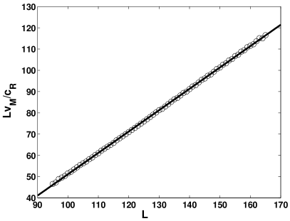
In order to test the quality the product structure approximation we should first show that the analytic equation (6) for the dynamics of a single macro crack describes correctly the corresponding dynamics in the lattice simulations. Multiplying Eq. (6) by we obtain
| (20) |
where is predicted to equal one. The parameter relates the material properties and boundary conditions of the lattice experiment to those in the continuum model. We simulated a single crack propagating without any additional damage, and measured as a function of . Next we fitted the data to Eq. (20). Figure 6 shows that the functional form given by Eq. (20) describes well the single crack dynamics in the lattice simulation. Moreover, we found that ; thus our procedure appears internally consistent. It should be noted that, notwithstanding the excellent agreement evidenced in Figure 6, there are a number of uncontrolled approximations at play here. First, the functional form in Eq. (20) is based on the assumption of a constant fracture energy. In fact, the fracture energy for our theoretical “lattice” material has been calculated, and it is not constant. Second, the simulation employs constant displacement boundary conditions in a finite strip (though, in order to mimic infinite medium, we specialized for times that do not allow wave interactions with the outer boundaries), and the theory assumes fixed stress at infinity. The excellence of the fit despite all this is somewhat unexpected, and bears further study.
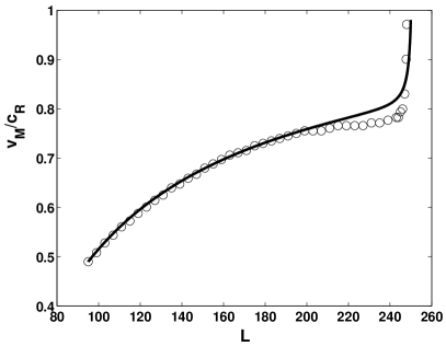
To directly test our product structure approximation Eqs. (13) we used the value of obtained by the linear fit and performed lattice simulation where a macro crack interacts with a colinear micro crack. We encounter a difficulty in the simulations since the micro crack tips were trapped even when the stress intensity factor exceeds the material threshold (7). This known phenomenon of lattice trapping is an artifact of the lattice structure; to overcome it we fixed the micro crack tips also in the analytic calculation. An example of the comparison between the simulation data and the analytic approximation is shown in Fig. 7. We found that our analytic approximation agrees with the simulated data, with deviations that are typically small. The largest errors are smaller than about even for . For larger ratios, which is the expected physical regime, we expect better approximations. Note that the fact that the analytic approximation overestimates the velocity of the macro crack is expected on physical grounds. Our product structure approximation relies on the fact that for short distances the information on the positions of the cracks tips, carried by elastic waves, flows almost instantly even if the typical cracks propagation velocities are of the order of . In reality it takes finite time for the stresses to reorganize themselves according to the new cracks tips positions and generally the energy release rate is lower than in our approximation.
The main conclusion of this section is that the product structure approximation Eqs. (13) gives very good predictions for the model problem studied here. We propose to interpret this in a broader way, and to test the applicability of this approximation in other contexts.
VI Summary and conclusions
This study has two aims; on the one hand, we are interested in the velocity fluctuations seen in dynamical crack propagation, and proposed here that the linear-elastodynamics interactions with micro cracks may very well be responsible for them. We did not address the reasons for the existence of the micro cracks - these may be there ab-initio or get born by the high stresses near the tip of the advancing cracks. On the other hand, we are after simplified methods of analysis of crack propagation in non-trivial environments. The technical difficulty of solving the full dynamical equations calls for approximate methods that work. With the motivation presented in Sect. III we demonstrated how the assumption of product structure for the stress intensity factors reduces the dynamics to a set of ordinary differential equations that are easily solved. The gratifying agreement with the lattice simulations emboldens us to propose this as an approach that may find applications in other contexts of interest. Only future work will help to strengthen or delineate the usefulness of this approach.
To further connect the interaction model to experimental observations one should couple our theory to a physically motivated model that will determined the conditions for micro cracks nucleation. Such a model will potentially predict the appearance of distributed damage in the process zone and the interaction with the macro crack may be related to the roughness of crack surfaces and the quasi-periodicity of the velocity fluctuations.
References
- (1) K. Ravi-Chandar and W.G. Knauss, Int. J. Frac. 26, 65 (1984).
- (2) K. Ravi-Chandar and W.G. Knauss, Int. J. Frac. 26, 141 (1984).
- (3) E. Sharon, S.P. Gross and J. Fineberg, Phys. Rev. Lett. 74, 5096 (1995).
- (4) E. Sharon and J. Fineberg, Phys. Rev. B 54, 7128 (1996).
- (5) K. Ravi-Chandar and B. Yang, J. Mech. Phys. Solids 45, 535 (1997).
- (6) K. Ravi-Chandar, Int. J. Frac. 90, 83 (1998).
- (7) E. Sharon and J. Fineberg, Nature 333, 397 (1999).
- (8) J. Fineberg and M. Marder, Phys. Rep. 313, 1 (1999).
- (9) L. B. Freund, Dynamic Fracture Mechanics, (Cambridge, 1998).
- (10) L.B. Freund, J. Mech. Phys. Solids 20, 141 (1972).
- (11) B.V. Kostrov, Int. J. Frac. 11, 47 (1975).
- (12) M. Adda-Bedia, Preprint, (2003).
- (13) K. B. Broberg, Cracks and Fracture, (Academic Press, 1999).
- (14) M. Abramowitz and I.A. Stegun, Handbook of Mathematical Functions (Dover, 1975).
- (15) L. I. Slepyan, Sov. Phys. Dokl. 26 538 (1981).
- (16) Sh. A. Kulamekhmetova, V. A. Saraikin and L. I. Slepyan, Mech. Solids 19, 102 (1984).
- (17) M. Marder and X. Liu, Phys. Rev. Lett. 71, 2417 (1993).
- (18) M. Marder and S. Gross, J. Mech. Phys. Solids 43, 1 (1995).
- (19) D. A. Kessler and H. Levine, Phys. Rev. Ebf 59, 5154 (1998).
- (20) D. A. Kessler, Phys. Rev. Ebf 61, 2348 (2000).
- (21) L. Pechenik, H. Levine andD. A. Kessler, J. Mech. Phys. Solids 50, 583 (2002).
- (22) D. A. Kessler and H. Levine, Phys. Rev. E68, art. no. 036118 (2003).