Spin polarization of electrons by non-magnetic heterostructures : basics of spin-optics.
Abstract
We propose to use the lateral interface between two regions with different strengths of the spin-orbit interaction(s) to spin-polarize the electrons in gated two dimensional semiconductor heterostructures. For a beam with a non zero angle of incidence the transmitted electrons will split into two spin polarization components propagating at different angles. We analyze the refraction at such an interface and outline the basic schemes for filtration and control of the electron spin.
pacs:
72.25.Dc, 72.25.Mk, 71.70.Ej, 73.23.AdThere is considerable interest in generating spin polarized current in semiconductor devices for the purposes of spintronics. The central idea is to polarize electrons using ferromagnetic materials with the subsequent injection of the polarized electrons into a semiconductor device for further applications DattaDas1990 . Despite the noticeable progress in the understanding the physics of this problem, the technology of the injection of the spin polarized electrons into a semiconductor system still remains unsettled; for a review see Ref. Wolf2001DasSarma2003Ohnol2003 .
In this letter we propose an alternative way to generate a spin polarized current in heterostructures using non magnetic semiconductor materials only, see also Ref. nonmagnetic2002 . We exploit the effect of the spin-orbit interaction(s) BychkovRashba84 ; Dresselhaus to polarize the electron beams. The principal element of the proposed spin polarizer contains an interface between two regions with different strengths of the spin-orbit interaction(s). As a result of the refraction at such an interface, for an electron beam with a non zero angle of incidence the transmitted electrons split into two beams with different spin polarizations propagating at different angles, and consequently, one can spatially separate the beams with different polarizations. The further applications of this effect are similar to that in optical devices exploiting the polarization of light. The proposed polarizing element can be realized in a two dimensional (2D) electron (hole) gas confined by an inhomogeneous quantum well. Such a well can be created either by manipulating the gates Nitta1997 ; Engels1997 ; Sato2001 ; Papadakis2001 , or by fabricating a laterally varying heterostructure.
Typically, the potential well has the shape of an asymmetric triangle, and, consequently, there is a direction of asymmetry, , perpendicular to the electron gas plane. This leads to the appearance of the Rashba spin-orbit interaction term BychkovRashba84 in the Hamiltonian, . We will study the case when the parameter varies along the -direction, and there is an interface at The direction of is chosen as Then the Hamiltonian has the form:
| (1) |
Here describes the varying bottom of the conduction band which may be controlled by gates. The current operator corresponding to this Hamiltonian contains a spin-dependent part, . The presence of spin in the current operator implies that in the process of scattering at the interface with varying the continuity conditions for the wave function will involve the spin degrees of freedom of the electrons. The situation is analogous to the refraction of light where the polarization of light enters the conditions determining the amplitudes of the refraction (Fresnel formulas).
To diagonalize the Hamiltonian with one has to choose the axis of the spin quantization along the direction . Then the electron states are described by their chiralities (referred to as and ). For an electron in a state with a definite chirality the spin polarization is perpendicular to the direction of motion. The dispersion relations of the two chiral modes are
| (2) |
Notice that for both modes the velocity depends on the energy in the same way Molenkamp2001 , and therefore under the stationary conditions the two spin components can be separated only if they are forced to move in different directions Halperin2003 .
Let us analyze the kinematical aspects of the scattering at the interface between the two regions with different All the waves participating in scattering have the same energy which determines their momenta as follows:
| (3) | |||||
Here we introduce a small dimensionless parameter which we will use throughout the paper. The conservation of the projection of the momentum on the interface together with Eq. (3) determine the angles of the transmitted and reflected beams (Snell’s law). Figure 1 illustrates the scattering for the simplest case when . The region without (or suppressed) spin-orbit term is denoted as N while the region with a finite is denoted as SO, and the directions of spin polarizations are indicated by the small arrows. In Fig. 1(a) an incident (unpolarized) beam comes from the N-region and when transmitted into the SO-region splits into two beams of different chirality that propagate at different angles. Thus the interface acts as a spin polarizer.
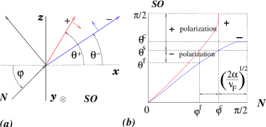
In Fig. 1(b) the angles of the two beams transmitted into the SO-region vs. the angle of incidence are plotted for the case . From Eq. (3) it follows that the SO-region is optically more dense for the mode (i.e., it has a smaller wave vector) and less dense for the mode. Correspondingly, the mode is refracted to larger angles than the one. Moreover, the mode exhibits a total reflection for an angle of incidence in the interval where is a critical angle for total internal reflection. We will use this fact in the discussion of spin filtration devices (see Figs. 3 and 4).
Another important fact for the spin filtration is that the mode has a limited aperture in the SO-region. Hence, there exists an interval of outgoing angles, , where only the component can penetrate. If it is possible to collect electrons from this interval, one will have an ideal spin filter. Potentially promising for spin filtration is an interval of incident angles . For an angle of incidence within this interval the transmitted beams of different chirality do not overlap. Namely, the mode scatters into the interval while the mode fills the interval , where is the angle of separation of the two polarizations [see Fig. 1(b) for a graphical definition of the angles , and ].
Remarkably, all angle intervals indicated in Fig. 1(b) are not so narrow as their widths have a square root dependence on . It follows from Snell’s law that . Actually one can reduce even further. With the gates acting selectively on the different regions of the electron gas, , one can alter the position of the bands relative to the Fermi level in the N- and SO-regions. A simple analysis based on Eq. (3) shows that with an increase of (i.e., lowering in the normal region) the angle interval grows and reaches . However, at that moment, which is optimal for spin filtration, the angle for total internal reflection reaches . Starting from this point the angle interval suitable for spin filtration narrows and eventually becomes , instead of
Let us analyze the scattering of electrons at the interface between two regions with different magnitudes of the Bychkov-Rashba term. The problem will be considered for the two cases of sharp and smooth interfaces Matsuyama2002 . For the clarity of the presentation we limit ourselves to the case of the interface between the N- and SO-regions only, and it will be assumed in what follows that . The scattering states of an electron coming from the N-region in the incident state is given by
| (4) |
where are spinors corresponding to the chiral modes in the N/SO-regions, and and are the amplitudes of the reflected and the transmitted waves. A similar expression holds also for which evolves from the incident state
For the sharp interface the amplitudes can be found from the continuity conditions that follow from the Schroedinger equation:
| (5) |
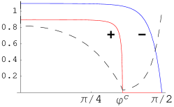
where denote . Analysis of Eq. ( 5) shows that in the course of refraction at the interface with transitions between waves with different chiralities are strongly suppressed. Namely, the amplitude , and similarly for . An extra factor of in the off diagonal amplitudes is a consequence of the fact that angles of deviation of the refracted electrons are small, and therefore the overlap of the spinors of different chiralities tends to vanish. The amplitudes and reach their maximal values at where deviation angles are maximal and . The intensities of the transmitted electrons without change of their chirality are plotted in Fig. 2. The drop of the intensities occurs practically only due to the reflection which becomes decisive for . Similar to and , the amplitudes of the reflection with a change of the chirality, and , are negligible at any angle. These amplitudes get their maximal value at Therefore, when total reflection occurs for the mode at its intensity is left mostly in the same mode.
At angles the amplitude is close to unity, while is still small (as well as ). It appears that for the angle of incidence equal to the ratio has a cusped minimum. For small this ratio has a limiting value at the minimum. Therefore, an unpolarized electron beam, when reflected, acquires a significant level of spin polarization at (see the dashed line in Fig. 2). The situation is analogous to the Brewster angle in the reflection of light. An angular interval around where the degree of polarization of the reflected beam remains large enough is not so narrow, see Fig. 2. This fact opens an opportunity to use reflection for the purposes of spin polarization.
Now we discuss the case of a smooth interface when changes weakly on the scale of the electron wavelength . One can conduct the analysis of the refraction at a smooth interface using a small parameter where is a characteristic scale of the variation of (i.e., an effective width of the interface). Due to the smoothness of the interface the electron spin will adjust itself adiabatically to the momentum keeping its polarization in the direction perpendicular to the momentum. In addition, for the reflected wave can be neglected if . Having these arguments in mind, we seek a solution which evolves from the state in the form which generalizes the WKB ansatz to include the spin degrees of freedom:
| (6) |
with and
To obtain an admixture of the wave with the opposite chirality, and , one has to analyze the Shroedinger equation up to first order in . This equation is similar to the one describing transitions in a two-level system subjected to an oscillating perturbation (the Rabi problem Rabi1937 ). The latter arises due to the phase difference of the two WKB waves in Eq. (6). The analysis shows that the admixture of a wave with different chiralities due to a smooth interface is very small, or (, whichever is smaller. In addition, the shape of the lines on Fig. 2 becomes more rectangular.
Summarizing the above consideration, one can state that for both the discussed cases each of the spin chiralities propagates along its own trajectory, while the change of the chiralities is very inefficient. Hence, the construction of spin filtering devices should be based on the kinematical separation of the trajectories of different chiralities. The N-SO interface analyzed so far for the case of the Rashba spin-orbit interaction was taken mostly for illustration purposes. Actually, any lateral interface in the presence of the spin-orbit interaction (of any kind BychkovRashba84 ; Dresselhaus ) will result in splitting of the trajectories which can be used for the purpose of spin polarization and filtration.
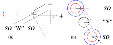
We now consider a spin polarization device presented schematically in Fig. 3a. The geometry of the device is analogous to the Glan style optical polarizers made of uniaxial crystals. A stripe with a reduced strength of the Bychkov-Rashba term is imposed across the SO conductor (SO-N-SO junction). The direction of the stripe is chosen in such a way that the angle of incidence of the electron beam exceeds the angle for total internal reflection for the mode. (It is the mode that can be totally reflected at the SO-N interface.) The mode will pass through the junction mostly unaffected, while the mode is redirected as shown in Fig. 3a. The reflected mode carry almost all of its initial intensity as the change of the chirality is inefficient: and . We do not show in Fig. 3a additional beams emerging on each side of the stripe as their intensity is negligible.
In Fig. 3b the kinematics of the refracted electrons is illustrated. The concentric circles represent spin split Fermi surfaces in each of the regions of the junction. The dashed lines are directed perpendicular to the stripe. They show that the projection of momenta on the direction of the interfaces is conserved. The kinematically allowed wave vectors in each of the regions are given by the intersection of the dashed lines with a circle. It is clear from this geometrical construction that for one of the electron modes to be totally reflected the corresponding dashed line should not have an intersection with the Fermi surfaces inside the stripe region.
The total internal reflection of electrons can be also used as a basis for the construction of a sort of a spin guide. In a narrow bending stripe of the “N”-region tangent electrons in the state will be trapped through total internal reflection, while electrons of chirality will leak out nanotech2003 . This guide acts also as a spin polarizer. The possibility of such device is based on the fact that the intensity of repolarization is very small.
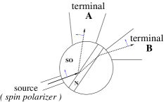
The high sensitivity of the trajectories of electrons to the magnitude of the parameter near the angle for the total internal reflection can be exploited for the construction of a switch of the spin current (spin transistor); see Fig. 4. Suppose the spin polarized electron beam is incident on SO-N (or N-SO) interface with an the angle of incidence very close to . Then the spin current can be switched between the terminals A and B by a small change of with the gate voltage. In this way an effective modulation of the spin current can be achieved.
Let us address the question of temperature. The effects under discussion are mostly controlled by the kinematics. Since the angle for total internal reflection is different for electrons with different energies, the temperature leads to a smearing of . The polarizing properties will not be influenced noticeably until the smearing . This leads to the condition: . Remarkably, this condition is not sensitive to the smallness of
In Ref. Sato2001 a large spin splitting in a gate controlled electron gas at In0.75Ga0.25As/In0.75Al0.25As heterojunction was reported. The observed splitting corresponds to . It was also demonstrated that the parameter may be reduced by a factor of with the gate voltage. If across the interface is chosen to be , the interval suitable for spin filtration can be as large as , which is wide enough for the feasibility of this proposal.
The size of the setup presented in Fig. 4 is determined by the distance between the spin polarizer and a stripe controlling the magnitude which can be of the order This distance should be shorter than a spin relaxation length.
Finally, we would like to point out the potential advantages of the proposed method. The spin polarized current can be comparable with the incoming unpolarized current. The compactness of the proposed setup makes it not very sensitive to the spin relaxation and disorder. The present experience of control of ballistic electrons Stormer2003 makes the proposed method of spin manipulations feasible.
The authors gratefully acknowledge the discussions with M. Heiblum and Y. Levinson.
References
- (1) S. Datta and B. Das, Appl. Phys. Lett. 56, 665 (1990).
- (2) S.A. Wolf et. al., Science 294, 1488 (2001); H. Ohno, F. Matsukura, and Y. Ohno, JSAP International 5, 4 (2002); S. Das Sarma, E.H. Hwang, and A. Kaminski, Solid State Commun. 127, 99 (2003).
- (3) M. Governale, D. Boese, U. Zulicke, and C. Schroll, Phys. Rev. B 65, 140403(R) (2002); T. Koga, J. Nitta, H. Takayanagi, and S. Datta, Phys. Rev. Lett. 88, 126601 (2002).
- (4) E.I. Rashba Fiz. Tverd. Tela (Leningrad) 2 ,1224 (1960) [Sov. Phys.-Solid State 2, 1109 (1960)]; Yu.A. Bychkov and E.I. Rashba, Pis’ma Zh. Eksp. Teor. Fiz. 39, 66 (1984) [Sov. Phys.-JETP Lett. 39, 78 (1984)].
- (5) G. F. Dresselhaus Phys. Rev. 100, 580 (1955).
- (6) J. Nitta, T. Akazaki, H. Takayanagi, and T. Enoki, Phys. Rev. Lett. 78, 1335-1338 (1997).
- (7) G. Engels, J. Lange, Th. Schäpers, and H. Lüth, Phys. Rev. B 55, R1958 (1997).
- (8) Y. Sato, T. Kita, S. Gozu, and S. Yamada, J. Appl. Phys. 89, 8017 (2001).
- (9) S.J. Papadakis, E.P. De Poortere, M. Shayegan, and R. Winkler, Physica E 9, 31 (2001).
- (10) L.W. Molenkamp, G. Schmidt, G. Bauer, Phys. Rev. B 64, 121202 (2001).
- (11) A way to create split packets by applying an ac perturbation was suggested by E.G. Mishchenko and B.I. Halperin, Phys. Rev. B 68, 045317 (2003).
- (12) The case of a sharp interface is studied here mostly for illustration purposes; for a useful discussion of a scattering through a sharp interface between a ferromagnet material and SO semiconductor see T. Matsuyama, C.-M. Hu, D. Grundler, G. Meier, and U. Merkt, Phys. Rev. B 65, 155322 (2002).
- (13) I.I. Rabi, Phys. Rev. 51, 652 (1937).
- (14) In the limit of the quantized transverse motion a spin guide was discussed by M. Valin-Rodriguez, A. Puente, and L. Serra, Nanotechnology 14, 882 (2003).
- (15) J. Spector, H.L. Stormer, K.W. Baldwin, L.N. Pfeifer, and K.W. West, Appl. Phys. Lett. 56, 967 (1990).