Stripe Order and Magnetic Transitions in La2-xSrxNiO4
Abstract
Magnetic order has been investigated in stripe-ordered La2-xSrxNiO4 () by d.c. magnetization and by polarized- and unpolarized-neutron diffraction. In the magnetically ordered phase, all three compositions exhibit a magnetic transition consistent with a spin reorientation in the plane. For , the spin axes rotate from an angle of 37.7 0.3∘ to the stripe direction at K, to 52.3 0.2∘ at K. The and compounds were found to undergo a similar spin reorientation. A spin reorientation has now been observed to occur for five different doping levels in the range , suggesting that this spin transition is an intrinsic property of the stripe phase.
I Introduction
La2-xSrxCuO4(LSCO) and La2-xSrxNiO4(LSNO) are isostructural, but it is well known that LSCO superconductsBednorz when sufficiently doped whereas LSNO does not. In LSNO the doped charges are known to localize in the form of charge stripes, i.e. periodically spaced lines of charges at to the Ni-O bonds. Antiferromagnetic ordering of the Ni spins between the charge stripes sets in at lower temperatures.yoshizawa-PRB-2000 The charge-stripes act as antiphase domain walls to the antiferromagnetic background. The pattern of incommensurate magnetic fluctuations in LSCOsuper resembles the magnetic order seen in LSNO, and this has been attributed to the existence of dynamic stripes in LSCO. The fluctuations in superconducting LSCO are centred on wavevectors parallel to the Cu-O bonds,yamada-PRB-2002 but the fluctuations in the non-superconducting state, , are centred on wavevectors at to the Cu-O bonds.superstripe These parallels suggest that charge stripe correlations may play an important role in superconducting LSCO. tranquada-Nature-1995
Charge-stripe order has been studied in LSNO by neutronneutron ; yoshizawa-PRB-2000 ; lee-PRB-2001 ; kajimoto-PRB-2001 ; kajimoto ; me and x-rayx-ray ; pash-PRL-2000 ; HATTON diffraction for doping levels in the range 0.135 0.5. As well as being static on the time scale probed by neutrons and x-rays, the charge stripes are found to be well correlated with correlation lengths in excess of 100 Å for certain levels of doping.yoshizawa-PRB-2000 ; pash-PRL-2000 ; HATTON These two properties make LSNO a good system for studying the basic properties of spin-charge stripes.
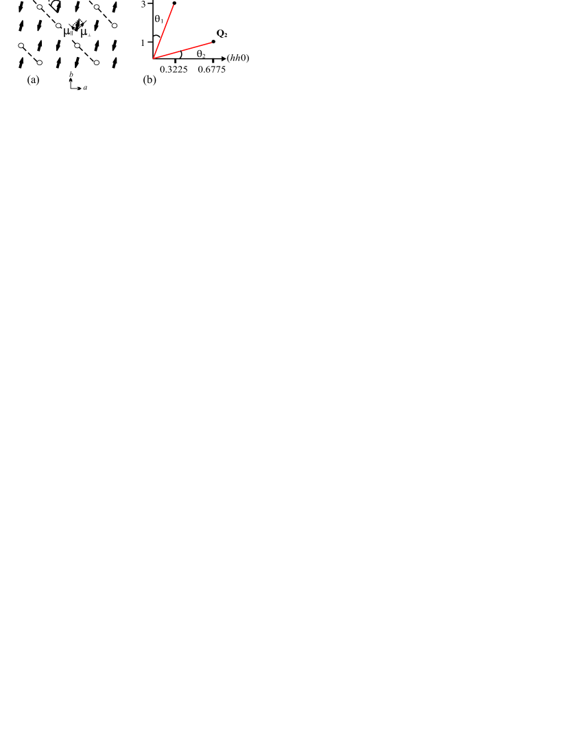
These studies have revealed many key facts about charge-stripe ordering including the variation of the stability of charge-ordering with doping. LSNO with = 1/3 has stripe order that is particularly stable owing to a commensurability effect that pins the charges to the lattice.ramirez-PRL-1996 ; yoshizawa-PRB-2000 ; kajimoto-PRB-2001 Figure 1(a) shows the commensurate charge-ordering that occurs for = 1/3. Although this figure shows the charge stripes only residing on the Ni sites, recent tunnelling electron microscopy work has shown the charge stripes can also reside on the O sites.Li-PRB-2003 The charge order is even more stable for , forming a ‘checkerboard’ pattern in the Ni-O2 layers at temeratures below , which becomes slightly incommensurate below .chen-PRL-1993 ; kajimoto
Lee et al.lee-PRB-2001 studied the magnetic order in LSNO crystals with and with polarized neutrons in order to determine the direction of the ordered moment. They concluded that at K the spins in the Ni-O2 layers are aligned at an angle to the stripe direction, where for and for . However, for the they found a reorientation transition at K such that on warming the spins rotate by an angle of towards the stripe direction. Freeman et al.me studied a sample with and observed a similar spin reorientation transition: in this case at , K, and .
Although this much is known about the spin orientation in LSNO the trends have not yet been fully established, and the mechanism driving the spin reorientation is not understood. Our new study was undertaken to try to address these questions by studying doping levels other than and .
We studied single crystals of La2-xSrxNiO4 grown by the floating-zone method,Prab using the techniques of magnetometry, (), polarized-neutron diffraction () and unpolarized-neutron diffraction (). The charge and magnetic ordering temperatures were found to be in good agreement with previous work on samples of similar doping.yoshizawa-PRB-2000 ; kajimoto The data reveal a spin reorientation similar in size and orientation to that in La5/3Sr1/3NiO4, but which is slower and occurs at lower temperatures, , for all three doping levels studied. These spin reorientations, unlike those in the or doped materials, all occur for incommensurate doping levels.
II Magnetization Measurements
Magnetization data were collected with a superconducting quantum interference device (SQUID) magnetometer (Quantum Design), with the field applied parallel to the plane of the crystal. The crystals used for the magnetization measurements had typical dimensions mm3. We carried out dc measurements either by cooling the sample in an applied field of 500 Oe parallel to the plane (FC), or by cooling in zero field then measuring while warming in a field of 500 Oe (ZFC).
In figure 2 we show the variation of the FC and ZFC magnetizations for . A subtle change of slope at K, marks the charge-ordering temperature, with a more pronounced gradient change at K marking the spin-ordering temperature. We observe from these results that this material exhibits irreversible magnetic behaviour, with a large FC–ZFC difference below K and a much smaller difference that persists to the charge-ordering temperature K with a slight widening around the magnetic ordering temperature, K. This is a typical feature for magnetization results on LSNO compounds that will be reported in detail elsewhere.unpublished Of most concern to the present work is the small but sharp drop in magnetization observed at K. The inset of figure 2 shows the field dependence of , which can be seen to decrease when increasing the applied field.
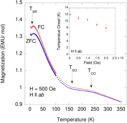
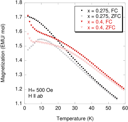
Figure 3 shows the variation of FC and ZFC magnetizations for the and . Like , both these materials are observed to have irreversible magnetic behaviour. The ZFC magnetization of the crystal has a rounded maximum at K. For there is no maximum, but the increase in magnetization with decreasing temperature first slows down and then begins to rise sharply below 5 K. The increase below 5 K could be due to a small amount of paramagnetic impurity in the crystal.
III Neutron Diffraction Measurements
The polarized neutron experiments were performed on the triple-axis spectrometer IN20 at the Institut Laue-Langevin. The energies of the incident and elastically scattered neutrons were selected by Bragg reflection from an array of Heusler alloy crystals. The data were obtained with initial and final neutron wavevectors of 2.66 Å-1. A PG filter was present between the sample and the analyzer to suppress scattering of higher-order harmonics. The unpolarized neutron experiments were performed on the triple-axis spectrometer RITA-II at SINQ at the Paul Scherrer Institut. The energies of the incident and elastically scattered neutrons were selected by Bragg reflection from a PG crystal. The data were obtained with initial and final neutron wavevectors of 1.55 Å-1, and a Be filter operating at 77 K was present between the sample and the analyzer to suppress scattering of higher-order harmonics.
For , single crystal rods of 7–8 mm diameter and 45 mm in length were used, and for the crystal was a slab of dimensions mm3. In this work we describe the structural properties of LSNO with reference to a tetragonal unit cell, with unit cell parameters , . The samples were mounted with the [001] and [110] crystal directions in the horizontal scattering plane. Scans were performed in reciprocal space either parallel to the (, , 0) direction at constant , or parallel to the (0, 0, ) direction at constant .
We begin by discussing the polarized-neutron diffraction results for . Initially, the neutron polarization was arranged to be parallel to the scattering vector , by an adjustable guide field of a few mT at the sample position. In this configuration a neutron’s spin is flipped during an interaction with electronic magnetic moments, but remains unchanged when scattered by a non-magnetic process, e.g. a lattice distortion. Thus by measuring the spin-flip (SF) and non-spin-flip (NSF) channels one can identify whether observed scattering is magnetic or not in origin.
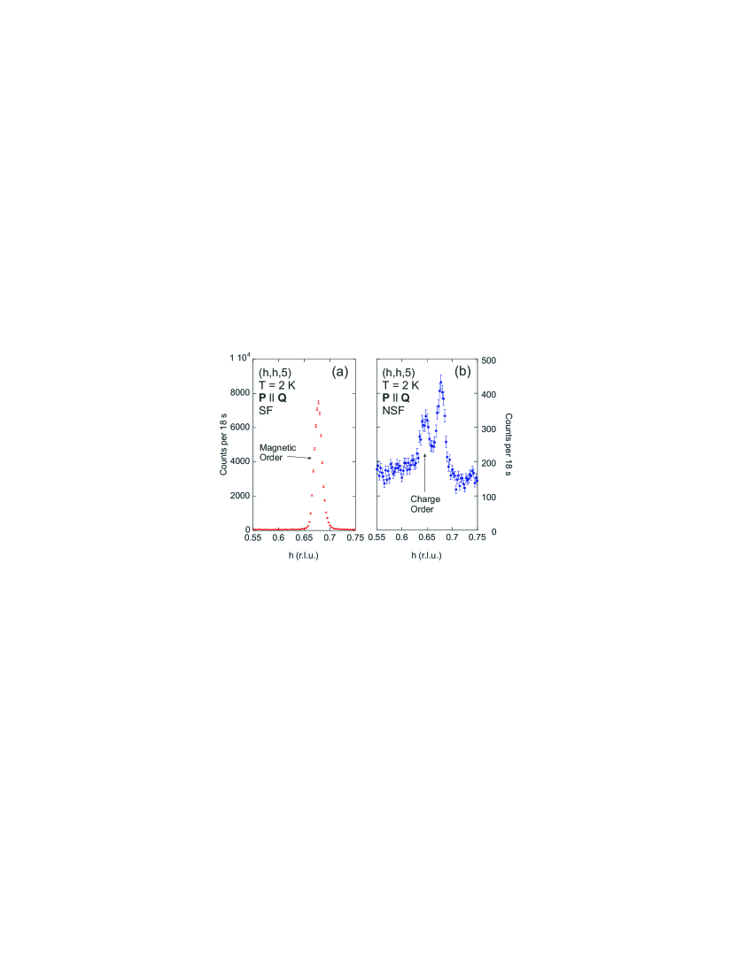
Magnetic order Bragg peaks were observed at (, , ) positions for all integer . This can be seen in figure 4(a), which shows the SF scattering for a scan parallel to ( 0) for = 5 at K. The peak positions corresponds to , consistent with previous measurements. yoshizawa-PRB-2000
Figure 4(b) shows the NSF scattering for the same scan as Fig. 4(a). The scan contains 2 weak peaks, one at 0.646 0.001 corresponding to charge ordering with an incommensurability of = 0.354 0.001, and the other at 0.678 corresponding to magnetic ordering. The latter appears in the NSF channel due to imperfect polarization of the neutron beam. We searched for the charge order peak at other equivalent positions, but only at 3 and 5 was there a measurable peak. From the temperature dependence of the charge peak in Fig. 4(b) we found K. By performing scans parallel to we were able to obtain the in-plane charge-order correlation length perpendicular to the stripe direction of 70 6 Å. This compares with a correlation length of 49 5 Å along the axis. These results show that the charge order is relatively three-dimensional.
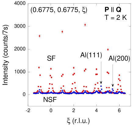
Figure 5 shows a scan parallel to through the magnetic order peaks. The widths of the peaks in this scan relate to the correlation length along the c-axis, however we observed that the correlation lengths for even and odd differ by a factor 2. That is, for even we obtain a correlation length of 53.2 1.4 Å and for odd we obtain a correlation length 108 2 Å . We performed scans parallel to on odd peaks, for which we obtained an in-plane correlation length perpendicular to charge stripe direction of 112.6 1.1 Å .
The intensities of the even and odd magnetic peaks were discussed in work on La2NiO4+δ, by P. Wochner et al..wochner-PRB-1998 For a commensurate stripe spin-ordering, such as , the stripes stack in a body centred arrangement and only the odd magnetic peaks are observed, with the systematic absence of the even peaks. However, for incommensurate spin-ordering with the stripes either pinned to the Ni or O sites,Li-PRB-2003 perfect body-centred stacking cannot be achieved. The disorder thus created, along with the additional disorder introduced due to differing Coulomb interactions between the layers, result in the presence of even peaks. Hence, odd peaks have a long correlation length as they come from the ideal long range body-centred stacking, whereas even peaks are a result of the disorder created on the smaller length scale of the non-ideal stacking.
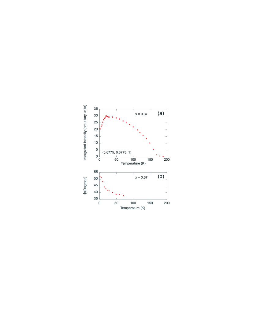
In figure 1(b) are shown the positions of two magnetic reflections Q1 = (0.3225,0.3225,3) and Q2 = (0.6775,0.6775,1). The vectors Q1 and Q2 are directed close to and , respectively. Since magnetic neutron diffraction is sensitive to spin components perpendicular to Q, the scattering at Q1 arises mainly from the total in-plane spin moment, while that at Q2 comes mainly from the spin components parallel to the stripe direction and along the c axis. Hence, we performed scans parallel to through Q2 at different temperatures to give a first indication as to whether there exists an in-plane spin reorientation like those observed for and 1/2. Figure 6(a) shows the temperature dependence of the magnetic reflection Q2. The magnetic ordering transition can be seen to occur at 170 K. On cooling below the intensity of Q2 can be seen to increase monotonically until it reaches a maximum at 20 K, then it is seen to decrease in intensity continuously to our base temperature. This anomalous behaviour correlates well with the transition observed in the magnetization, Fig. 2, and indicates a spin reorientation below 20 K.
To fully analyze the direction of the spins over this temperature range we varied the direction of the neutron polarization P relative to the scattering vector Q, measuring at the and positions. The method is described in Ref me, , where the expressions used to obtain the spin direction are given. A correction for the slightly non-ideal performance of the polarization elements of the instrument was calculated from the flipping ratio of 18 1 measured on the magnetic Bragg peaks.
Polarization analysis of both the Q1 and the Q2 Bragg peaks revealed that the moment lies in the plane to within 1∘ in the temperature range K. Having established this, we subsequently assumed the -axis component to be zero and analyzed the polarization at Q1 to determine the in-plane moment. From this analysis we determined that the spins rotated from an angle of 37.7 0.3∘ to the stripe direction at = 71 K to 52.3 0.2∘ at = 2 K, as shown in Fig. 6(b). The transition occurs mainly between 10 and 20 K, but slowly develops from below K.
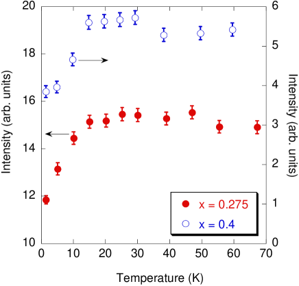
We performed unpolarized neutron diffraction at equivalent Q1 and Q2 positions on the single crystals with and , using the instrument RITA-II at SINQ. We found a similar behaviour to the results just described. In particular, the temperature dependence of the Q2 = (0.645,0.645,0) magnetic Bragg peak for , and of the Q2 = (0.685,0.685,1) magnetic Bragg peak for , both have a maximum similar to that shown in Fig. 6(a) for . By contrast, the intensities of the Q1 Bragg peaks are almost constant below 20 K. The temperature dependence of the Q2 intensity is shown on Fig. 7 for both and . The drop in Q2 intensity at low temperature implies a spin reorientation in and similar in nature to that in .
Unpolarized neutron diffraction cannot accurately determine without a detailed analysis of the intensities of many diffraction peaks, but we can estimate from the drop in intensity of the Q2 peak below K and the value of for , assuming the ordered moment remains in the plane and fixed in magnitude in this temperature range. Taking above for ,lee-PRB-2001 and using for (based on the observations for at ). We find for both and , similar to .
IV Discussion and Conclusions
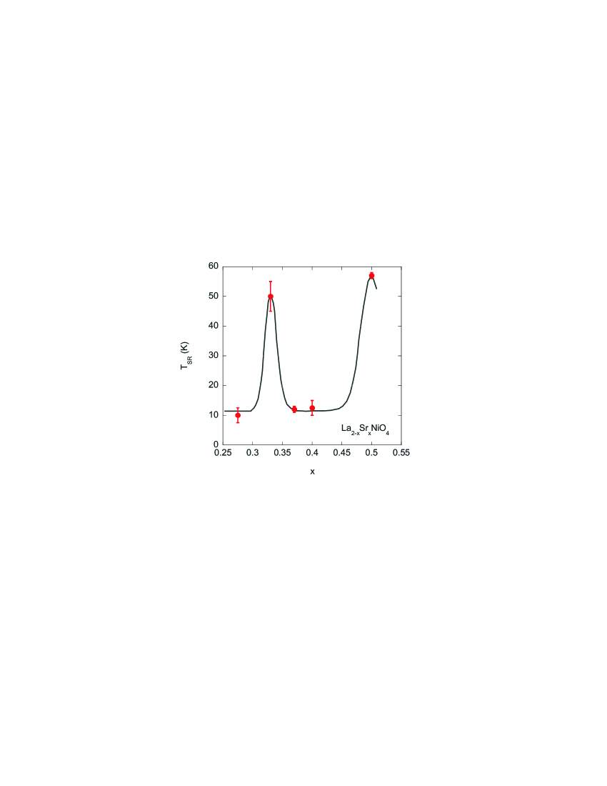
There are differences and similarities between the spin reorientations reported here for = 0.275, 0.37 and and those that occur for = 1/3,lee-PRB-2001 and .me In each case the spins rotate in the same sense, away from the stripe direction on cooling. The size of the reorientation in = 0.37 ( ) (and more approximately in and ) is similar to that in = 1/3 ( ), but smaller than in = 1/2 ( ). However, in and the spin reorientation occurs at a much lower temperature, K, compared with K for = 1/3 and K for = 1/2. Figure 8 summarises the variation of with that has so far been established for the doping range . The results indicate that if there is no commensurate charge ordering the spin reorientation occurs K, but if there is a commensurate charge ordering the spin reorientation occurs at K.
There is also evidence of a trend in the direction of the ordered moment. The base temperature spin orientations are for = 1/3, for , and for = 1/2, with charge ordering temperatures of K, K, K respectively. We can add to this list an estimate of for , (charge ordering temperature ) based on the angle of at 11 K found by Lee et al. lee-PRB-2001 , with an additional due to the spin reorientation on cooling to 2 K. Hence, there seems to be a correlation between the spin orientation angle and the charge-ordering temperature. Further measurements on samples with doping levels between and 0.5 would be useful to confirm this trend.
Up to now, spin reorientations in La2-xSrxNiO4 had only been observed in materials with especially stable charge order ( and 1/2). The existence of a spin reorientation in = 1/2 has shown that a commensurate spin-stripe order is not required for a spin reorientation to occur.me The new results on = 0.275, 0.37 and 0.4 presented here further show that not even commensurate doping is required. It is likely that LSNO at all doping levels in the range undergo a spin reorientation, but that is larger at the commensurate doping compositions.
This work was supported in part by the Engineering and Physical Sciences Research Council of Great Britain. Some of this work was performed at the Swiss Spallation Neutron Source SINQ, Paul Scherrer Institute (PSI), Villigen, Switzerland.
References
- (1) J. G. Bednorz and K. A. Müller, Z. Phys. B 64, 189 (1986)
- (2) H. Yoshizawa et al., Phys. Rev. B 61, R854 (2000)
- (3) T. R. Thurston et al., Phys. Rev. B 40, 4585 (1989); S-W. Cheong et al., Phys. Rev. Lett. 67, 1791 (1991); T. E. Mason, G. Aeppli, and H. A. Mook, Phys. Rev. Lett. 68, 1414 (1992); T. R. Thurston et al., Phys. Rev. B 46, 9128 (1992);
- (4) K. Yamada. et al., Phys. Rev. B 57, 6165 (1998).
- (5) S. Wakimoto et al., Phys. Rev. B 60, R769 (1999); S. Wakimoto et al., Phys. Rev. B 61, 3699 (2000); M. Matsuda et al., Phys. Rev. B 62, 9148 (2000); M. Fujita et al., Phys. Rev. B 65, 064505 (2002).
- (6) J. M. Tranquada et al., Nature (London) 375, 561 (1995).
- (7) S. M. Hayden et al., Phys. Rev. Lett. 68, 1061 (1992); V. Sachan et al., Phys. Rev. B 51, 12742 (1995); J. M. Tranquada, D. J. Buttrey, and V. Sachan, Phys. Rev. B 54, 12318 (1996);
- (8) S-H. Lee et al., Phys. Rev. B 63, 060405 (2001)
- (9) R. Kajimoto et al., Phys. Rev. B 64, 144432 (2001)
- (10) R. Kajimoto et al.,Phys Rev B 67, 014511 (2003)
- (11) P. G. Freeman et al., Phys. Rev. B 66, 212405 (2002)
- (12) E. D. Isaacs et al., Phys. Rev. Lett. 72, 3421 (1994); A. Vigliante et al., Phys. Rev. B 56, 8248 (1997)
- (13) Yu. G. Pashkevich et al., Phys. Rev. Lett. 84, 3919 (2000)
- (14) P. D. Hatton et al., Physica B 318, 289 (2002)
- (15) A. P. Ramirez et al., Phys. Rev. Lett. 76, 447 (1996)
- (16) Jianqi Li et al., Phys. Rev. B 67, 012404 (2003)
- (17) C. H. Chen, S-W. Cheong, and A. S. Cooper, Phys. Rev. Lett. 71, 2461 (1993)
- (18) D. Prabhakaran, P. Isla, and A. T. Boothroyd, J. Cryst. Growth 237, 815 (2002)
- (19) P. G. Freeman et al., to be published in J. Magn. Magm. Mat.; P. G. Freeman et al., unpublished work.
- (20) P. Wochner et al., Phys. Rev. B 57, 1066 (1998)