Role of wave interaction of wires and split-ring
resonators for the losses in a left-handed composite
Abstract
In this work the analytical model explaining the losses in the known two-phase lattice of D. Smith, S. Schultz and R. Shelby representing a uniaxial variant of left-handed medium (LHM) at microwaves is presented. The role of electromagnetic interaction between split-ring resonators (SRRs) and straight wires leading to the dramatic increase of ohmic losses in SRRs within the band when the meta-material becomes a LHM is clarified. This paper explains why in this structure, rather high transmission losses are observed in the experimental data, whereas these losses in a separate lattice of SRRs and in a lattice of wires are negligible at these frequencies.
pacs:
41.20.Jb, 42.70.Qs, 77.22.Ch, 77.84.Lf, 78.70.Gq1. Introduction
In his seminal work Veselago68 V. Veselago summarized an extensive study of electromagnetic properties of media with real and negative parameters called as left-handed materials (LHM). Since 2000 this topic has become a subject of an abundant discussion initiated by J. Pendry lens . In 2001, the negative refraction (a feature of LHM that allows to distinguish these media from conventional ones) was demonstrated in the microwave range by the group of D. Smith Shelby2001 . Since 2001 this result has been several times reproduced (see Lu and Houck ) and now is considered as reliable. The material designed in Shelby2001 is essentially a two-phase composite, where the two phases are respectively responsible for electric and magnetic polarization effects. The negative real part of effective permittivity was created by an array of parallel conducting wires (whose direction determines the optical axis of the composite medium), which is known to behave similarly to a free-electron plasma at enough low frequencies. The negative value of the real part of permeability was provided by double split-ring resonators (SRRs), see also Pendry1999 . This negative permeability arises due to the resonance of the magnetic polarizability of SRRs within a very narrow sub-band which belongs to their resonant band. This sub-band lies in the wide frequency range where (more exactly the real part of a component of the permittivity tensor is negative). The meta-material becomes a LHM within this sub-band for waves polarized along and propagating orthogonally to this axis. These electromagnetic waves suffer the magnetic and dielectric losses. There has been a whole literature written about these losses since the work by N. Garcia and M. Nieto-Vesperinas Garcia . In this work the structure tested in Shelby2001 is treated as opaque and an exotic explanation of negative refraction is presented. Comparing the results obtained in the group of N. Garcia (Garcia , Garcia1 , etc) or the results obtained in the group of A.L. Efros (e.g. in Pokrovsky ) with the data of the group of C. Soukoulis (e.g. in Soukoulis ) one can see that different simulations of the same lattice give very different results for the transmission losses per unit thickness (from practical absence to huge values). Experimental data do not fit with all these simulations and give moderate values for transmittance in the LHM regime. The disagreement of the data from Soukoulis with the experiment is referred in this work to the influence of the dielectric board, but it is only a guess. It has not been clearly stated which losses dominate in this meta-material: ohmic losses or dielectric losses. However, it is clear that the losses are rather significant and should be studied once more.
Note, that few alternative versions of a LHM at microwaves were suggested in the literature, e.g. sim1 and book . In sim1 the self-consistent analytical theory of the quasi-isotropic lattice of metal bianisotropic (Omega) particles has been presented, and the negative parameters predicted within the band GHz. However, the losses were neglected in this work. In book the experimental testing of a LHM made from SRRs combined with capacitively loaded strips (instead of long wires) has been done. The aim of this work (as well as sim1 ) was to obtain an isotropic variant of LHM and to match this medium to free space. The losses in this structure are very high (the mini-pass-band corresponding to negative material parameters is almost invisible within the band of the resonant absorbtion of SRRs), and the band in which both material parameters extracted from measured data have negative real parts is rather narrow. A MHz band has been detected at GHz and another one were located around GHz (however at these frequencies the lattice period becomes longer than and the local constitutive parameters are not physically sound.) In proceedings the transmittance through the layer of a racemic medium from resonant chiral particles is calculated. This medium also exhibits negative real part of constitutive parameters within the resonant band. However, the result for resonant transmission losses in proceedings is pessimistic.
Therefore in the present paper we return to the structure suggested by the group of D. Smith. We use a self-consistent analytical model for its material parameters taking into account ohmic and dielectric losses. The similar structure in its lossless variant has been already studied in sim2 where the analytical model was presented for its material parameters. The difference of the structure suggested in sim2 with that from Shelby2001 was another geometry of a SRR. We considered in sim2 the SRRs suggested by R. Marques instead of SRRs of J. Pendry. The resonator of R. Marques is not bianisotropic, whereas the lattice of D. Smith, S. Schultz and R. Shelby is in fact a weakly bianisotropic medium within the resonant band of SRRs (see Marques ). The aim of sim2 was to find the band-gap structure of the meta-material. In the present paper we consider the SRRs of J. Pendry assuming that these are prepared from a wire with round cross section. In Shelby2001 the SRRs were prepared from a thin metal strip. However, this is not a principal difference in what concerns the scattering properties of a SRR as was clearly shown in Bruno and Bruno1 . Our choice of the usual wire instead of a strip wire is explained by absence of an analytical model of losses for curved strip wires. We consider at the first step the lattice of parallel SRRs and at the second step we study the meta-material from Shelby2001 . Comparing the result for the effective permeability of two meta-materials: SRRs with wires and SRRs only we can see the role of the electromagnetic interaction in the two-phase material.
2. Calculations of magnetic losses in a lattice of SRRs
In the model of the dense lattice of SRRs presented in Pendry1999 , the calculation of ohmic losses did not take into account the curvature of wires. In this section we calculate these losses, using the Landau formula for a wire ring Landau . To find the permeability, we apply the rigorous model of the dipole lattice developed in JOSA for electric dipoles and in PRE for non-reciprocal magnetic dipoles. The result we obtain in this section confirms the result from Pendry1999 : the resonant absorption in this lattice is rather small in the frequency band where .
We study the case of coplanar SRRs suggested in Pendry1999 . The model of a single SRR is needed to calculate a magnetic polarizability which enters into dispersion equation of a lattice of magnetic dipoles derived in PRE . The magnetic polarizbility is defined as a relation of its magnetic moment to the local magnetic field (polarized along the axis, i.e. orthogonally to the SRR plane)
We consider SRRs consisting of two wires with round cross section. The model of such SRRs was developed and validated by numerical simulations in our works Bruno ; Bruno1 for the lossless case. The conductivity resistance of the ring can be calculated using the formula Landau
| (1) |
Here is the radius of the wire cross section and is the effective complex conductivity which is expressed through the metal conductivity as follows:
where is the skin depth. The model of a lossless SRR from Bruno1 is rather accurate but sophisticated. It takes into account the non-uniformity of the current induced in both rings and allows to calculate not only the magnetic polarizability of a single SRR but also electric and magneto-electric polarizabilties. Since formula (1) implies the uniform distribution of the current around the rings of SRR (and we want to obtain a self-consistent model of losses), we put in formula (47) of Bruno1 . These coefficients describe the non-uniformity of the induced current around the rings of SRR. When we neglect them, the long formula (12) from Bruno1 for magnetic polarizbility of a single SRR simplifies to a classical two-time derivative Lorentz relation (formula (19) from Bruno1 ):
| (2) |
, is the averaged area of SRR, where and are radii of the outer and inner rings (which are assumed to be close to one another), is the averaged proper inductance of rings and is their mutual inductance.
Let us first consider the lossless case. Then the factor in (2) determines radiation losses in the random medium of SRRs Bruno and is proportional to the radiation resistance of the SRR, . Here is the wave impedance and is the wavenumber of the host medium. Consequently, (see formulae (17,20) from Bruno1 ). This result allows to our model to satisfy the basic condition for any magnetic dipole (for electric dipoles this condition introduced by Sipe and Kranendonk in Sipe ):
| (3) |
Notice, that this condition (which is obvious for both classical and quantum scatterers and fits with the well-known Landau correction to the Lorentz theory of dispersion) was violated in the approximate model introduced in Pendry1999 .
Let us now study the cubic lattice of parallel lossless SRRs with period . To find of the lattice we use the relation , where is the refraction index related with the propagation factor of the basic propagating mode . Factor (within the basic Brillouin zone) can be found from the known dispersion equation for modes propagating along or axes in a lattice of magnetic dipoles PRE . Equation (21) from PRE for a simple cubic lattice of parallel magnetic dipoles can be written in our notations as
| (4) |
where and . The same equation can be obtained from JOSA using the duality principle. This equation was obtained using the method of the local field. It gives the band-gap structure of the lattice with real in pass-bands and negative imaginary in stop-bands. Within the resonant band of a scatterer when the well-known complex mode (inherent to metallic photonic crystals) appears and . One can see from equation (4) that the radiation resistance of the scatterer does not influence the final parameters of a lattice. This results from the electromagnetic interaction in regular structures. The imaginary part of the interaction constant of arbitrary regular lattice exactly compensates the contribution of the radiation resistance into inverse polarizability of scatterers JOSA . In (4) the term has disappeared since it is totally compensated by the imaginary part of the lattice interaction factor PRE .
Now consider the case when is non-zero. In this case the relation (3) naturally generalizes to
| (5) |
First term of (5) is still totally compensated by the interaction constant of the lattice, but the second term remains and modifies (4). In this lossy case we should substitute into (4) the value instead of . Here is given by (2) with the substitution .
Our numerical example corresponds to the following parameters: relative permittivity of the host matrix , mm, mm, wire radius mcm (it is still times as larger as at GHz). Copper conductivity . The period of a lattice of SRRs was taken equal mm. The dispersion plot (see Fig. 1, on top), shows the normalized propagation factor versus frequency and contains two results. The first one (straight dashed line) corresponds to the polarization of electric field along and of magnetic field in the plane . Then the SRRs are not excited. The second one corresponds to another polarization of the mode, when the SRRs are excited. There is practically the lossless complex mode within the lower half of the resonant frequency band of SRRs and the usual stop-band within its upper half. The difference with the lossless case exists but is not visible in the plot. In fact, the losses make be complex at all frequencies, however this correction is maximally of the order .
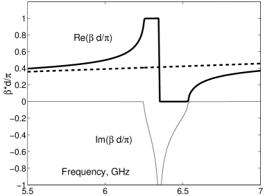
Therefore the result for presented in Fig. 1, on bottom, is optimistic. Within the band GHz we obtained whereas . Though we have considered SRRs from wires with round cross section, we have chosen a very small value for . We expect that our results correspond to a strip wire with width of few tenth of mm. However, we will see below that this result cannot be expanded to the lattice of SRRs and wires. Though the quasi-static interaction between SRRs and wires is absent in the lattice Shelby2001 , the wave interaction exists. It was clearly demonstrated in sim2 that this interaction (in the lossless case) strongly influences the real part of the material parameters. In the next section we will find its influence to their imaginary parts.
3. Lattice of wires and SRRs
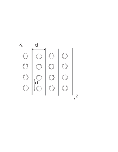
In this section we study the effective material parameters of the two-phase lattice of SRRs and wires. It is almost the same structure as in sim2 but the metal of SRRs is not perfect (e.g. a copper) and the background dielectric has small losses. We assume that the wires and SRRs are located in a uniform host medium (see Fig. 2, on top). Our goal is not to calculate the true losses in the meta-material described in Shelby2001 but to understand the impact of the electromagnetic interaction on these losses. In fact, in sim2 the structure uses the modified SRRs of R. Marques, whose electric polarizability is very small at the resonance of , and magnetoelectric polarizability is zero. In the present paper we consider the SRRs of J. Pendry, the ones used in Shelby2001 . However, it does not change the dispersion equation from sim2 since we neglect the electric and magnetoelectric polarizabilities of SRRs. These are not negligible for quantitative calculations but are not important enough for our purposes. All we need to modify in the theory is to add the term to the radiation resistance of a SRR denoted as in formula (10) of sim2 . Repeating the steps which led from equation (10) to (29), we obtain the following dispersion equation for waves propagating along the axis
| (6) |
Relation (6) results of sim2 with the only substitution . In (6) is the radius of straight wires. Longitudinal component of the effective permittivity and are determined (respectively) by formulas (35) and (36) of sim2 .
In our numerical example, the lattice of SRRs is the same as in the precedent section and it is assumed that . The result for permeability dramatically differs from the previous result ; this due to the electromagnetic interaction of SRRs and wires. This interaction is described by the parameter in equations (27) and (28) of sim2 . If one formally puts , the problem splits in two independent dispersion equations, one for the medium of SRRs and one for the wire medium. Then keeps the same values as in Fig. 1.
On Fig. 2, we have shown the dispersion plot of the structure. This plot corresponds to same permittivity of host medium as in the previous section. Comparing this plot with similar plot for lossless structure (Fig. 5 of sim2 ) one finds that the complex mode (in Fig. 5 it corresponds to the lower half of the resonant band of SRRs) disappears. Instead, the forward wave with strong attenuation appears in this resonant sub-band. This forward wave corresponds to and , and the propagation is possible due to the complexity of constitutive parameters. The attenuation factor is larger than the propagation one in this band. The upper half of the resonant band of SRRs contains the backward wave as well as in Fig. 5 of sim2 . The ohmic losses broaden the frequency band of this backward wave, however these also produce the visible imaginary part of the propagation factor in this band. This imaginary part is not so high as in the lower half of the resonant band and is related with ohmic losses in SRRs. It is practically not affected by imaginary part of (until the threshold , when the influence of the dielectric losses in the matrix becomes visible in the dispersion plots). In this sub-band decreases if one increases the wire radius and increases if one decreases .
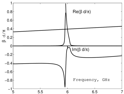
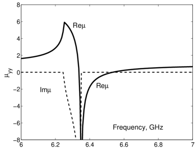
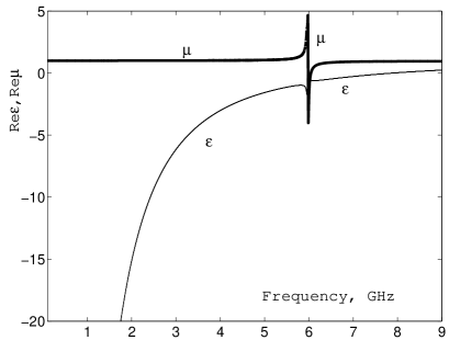
In Fig. 3 we present the frequency behavior of and for the structure under study. Here means the component of tensor , and similarly . On top the wide-band frequency dependence is shown for real parts of (thin line) and (thick line). One can see that both parameters are resonant. This is the result of the electromagnetic interaction between wires and SRRs (which also leads to the small shift of the resonant frequency for compared to that of a single lattice of SRRs). Though the resonance of permittivity is weak, it remains negative within the resonant band of SRRs. This resonance confirms once more that the very simplistic approach, in which the constitutive parameters of the meta-material are obtained with the trivial superimposition of of SRRs and of wires, is not applicable in most of cases sim2 . On the bottom of Fig. 3, both real and imaginary parts of these parameters are presented within the resonant band of SRRs. The band of the backward wave (the upper sub-band of the resonant band of SRRs) is the one in which the meta-material becomes the LHM. Unlike in the precedent section, in this sub-band the absolute value of is quite high. We obtained within the frequency band of the backward wave (i.e. of the negative material parameters). This result explains the experimental data for transmittance that can be found in the literature.
Note, that introducing the finite conductivity for straight wires practically does not change the result. The ohmic losses in straight wires do not pose a difficult problem since the negative permittivity of wire lattice is not resonant. But the permeability of the lattice of SRRs is resonant and it makes possible the strong influence of wires to SRRs. This is the reason of high magnetic losses in the backward-wave regime.

4. Conclusion
In this paper we considered the problem of the influence of ohmic losses in the metal and dielectric losses in the host matrix to the magnetic and dielectric losses in the two-phase composite medium formed by a square lattice of infinitely long parallel wires and a cubic lattice of symmetrically located SRRs. It has been shown that the electromagnetic interaction between wires and SRRs together with ohmic losses in SRRs give rather significant magnetic losses. These losses are absent from the single lattice of SRRs. This way we suggest an explanation of the rather significant transmission losses in the structure from Shelby2001 which is considered as a uniaxial variant of left-handed material. We do not deny the significance of the losses in the dielectric board, which support the SRRs prepared from copper strips. However, the contribution of ohmic losses is also rather important.
We have shown that the wave interaction of electric and magnetic components of the meta-material is harmful for its transmittance. It is impossible to avoid this interaction. The transmittance can be improved reducing the ohmic resistance of SRRs. Increasing the width of the strip wire or the radius of the usual wire one can obtain the better transmission properties of the meta-material over the whole resonant band in spite of the electromagnetic interaction in the meta-material.
References
- (1) V.G. Veselago, “The electrodynamics of substances with simultaneously negative values of and ”, Soviet Physics Uspekhi, vol. 10, pp. 509-514, 1968. (originally in Russian in Uspekhi Fizicheskikh Nauk, vol. 92, no. 3, pp. 517-526, July 1967)
- (2) J.B. Pendry, “Negative refraction makes a perfect lens”, Phys. Rev. Lett., vol. 85, no. 18, pp. 3966-3969, 2000.
- (3) R.A. Shelby, D.R. Smith and S. Schultz, “Experimental verification of a negative index of refraction”, Science, vol. 292, pp. 77-79, 2001.
- (4) K. Lu, J. McLean, R. Gregor, C. Parazzoli and M.H. Tanelian, “Free space focused beam characterization of left-handed materials”, Appl. Phys. Lett., vol. 82, pp. 2535-2537, 2003.
- (5) A. Houck, J. Brack, I. Chuang, “Experimental observation of a left-handed material that obeys Snell’s law”, Phys. Rev. Lett., vol. 90, pp. 137401(1-4), 2003.
- (6) J.B. Pendry, A.J. Holden, D.J. Robbins, and W.J. Stewart, “Magnetism from conductors and enhanced nonlinear phenomena”, IEEE Trans. Microw. Theory Tech., vol. 47, no. 11, pp. 2075-2084, 1999.
- (7) N. Garcia and M. Nieto-Vesperinas, “Negative refraction does not make perfect lens”, Phys. Rev. Lett., vol. 88, no. 12, pp. 122501(1-3), 2002.
- (8) E.V. Ponizovskaya, M. Nieto-Vesperinas and N. Garcia, “Losses for microwave transmission metamaterials for producing left-handed materials. The strip wires”, submitted to Phys. Rev. B, available at cond-mat/0206429.
- (9) A.L. Pokrovsky and A.L. Efros, “Electrodynamic of metallic photonic crystals and the problem of left-handed materials”, Phys. Rev. Lett., vol. 89, no. 10, pp. 093901(1-4), 2002.
- (10) P. Markos and C.M. Soukoulis, “Transmission studies of the left-handed materials”, Phys. Rev. B, vol. 65, pp. 033401, 2002.
- (11) C.R. Simovski and S. He, “Frequency range and explicit expressions for negative permittivity and permeability for an isotropic medium formed by a lattice of perfectly conducting Omega-particles”, Phys. Lett. A, vol. 311, pp. 254-263, 2003.
- (12) R.W. Ziolkovski, “Design, fabrication and testing of double negative metamaterials”, IEEE Trans. Antennas. Propag., vol. 51, no. 7, pp. 1516-1529, 2003.
- (13) S.A. Tretyakov, I.S. Nefedov, C.R. Simovski and S.I. Maslovski, “Modelling and microwave properties of artificial materials with negative parameters”, in Advances in electromagnetics of complex media and meta-materials, S. Zouhdi, A. Sihvola and M. Arsalane (eds), NATO Series II, vol. 89, Kluwer Academic Publishers, pp. 99-122, 2002.
- (14) S.A. Tretyakov and A.J. Viitanen, Plane waves in regular arrays of dipole scatterers and effective medium modelling, JOSA, vol. 17, No 10, pp. 1791-1797, 2000.
- (15) L.D. Landau, E.M. Lifshitz, Electrodynamics of continuous media, Pergamon Press, NY, 1986.
- (16) C.R. Simovski, P.A. Belov and S. He, “Backward wave region and negative material parameters of a structure formed by lattices of wires and split-ring resonators”, IEEE Trans. Antennas. Propag., vol. 51, no. 10, pp. 2582-2591, 2003.
- (17) R. Marques, F. Medina and R. Rafii-Idrissi, “Role of bi-anisotropy in negative permeability and left-handed metamaterials”, Phys. Rev. B, vol. 65, pp. 144440(1-4), 2002.
- (18) C.R. Simovski, B. Sauviac, “Toward creating the isotropic left-handed material”, Radio Science, 2004 (in print).
- (19) B. Sauviac, C.R. Simovski, S.A. Tretyakov, “Double split-ring resonators: analytical modeling and numerical simulations”, Electromagnetics, 2004 (in print).
- (20) P.A. Belov, S.A. Tretyakov and A.J. Viitanen, “Non-reciprocal microwave band-gap structure”, Phys. Rev. E, vol. 66, pp. 016608(1-6), 2002.
- (21) J.E. Sipe and J. van Kranendonk, “Macroscopic electrodynamic theory of resonant dielectrics”, Phys. Rev. A, vol. 9, pp. 1806-1822, 1974.