Optical properties of photonic crystal slabs with asymmetrical unit cell
Abstract
Using the unitarity and reciprocity properties of the scattering matrix, we analyse the symmetry and resonant optical properties of the photonic crystal slabs (PCS) with complicated unit cell. We show that the reflectivity is not changed upon the 180∘-rotation of the sample around the normal axis, even in PCS with asymmetrical unit cell. Whereas the transmissivity becomes asymmetrical if the diffraction or absorption are present. The PCS reflectivity peaks to unity near the quasiguided mode resonance for normal light incidence in the absence of diffraction, depolarisation, and absorptive losses. For the oblique incidence the full reflectivity is reached only in symmetrical PCS.
pacs:
42.70.Qs, 42.25.BsThe physics of photonic crystal slabs (PCS) Maradudin and McGurn (1993); Labilloy et al. (1997); Astratov et al. (1999) receives much attention in recent years because of many interesting possibilities they open to control the light interaction with matter. The tendency is toward the PCS sophistication: nanostructured metals or semiconductors are included, and the unit cell geometry, using modern technology, becomes more complicated. As a result, new tools for photonic engineering become available. A well known example is the extraordinary optical transmission through sub-wavelength hole arrays in metal films Ebbesen et al. (1998); Ghaemi et al. (1998). Another promising example are polaritonic crystal slabs with nanostructured semiconductors Fujita et al. (1998); Yablonskii et al. (2001); Shimada et al. (2002). The physics behind is the coupling between photonic and different electronic resonances in such structures. They manifest themselves via pronounced resonant Wood’s anomalies Wood (1902); Fano (1941); Hessel and Oliner (1965) in the optical spectra, due to the excitation of quasiguided Labilloy et al. (1997); Astratov et al. (1999); Paddon and Young (2000); Ochiai and Sakoda (2001); Fan and Joannopoulos (2002); Tikhodeev et al. (2002) or surface plasmon Ritchie et al. (1968); Ebbesen et al. (1998); Schroeter and Heitmann (1999); Dykhne et al. (2003) or both Christ et al. (2003) modes. On the other hand, making complicated unit cells, e.g., characterized by a lack of 180o-rotational symmetry in the PCS plane Schroeter and Heitmann (1999); Fujita et al. (2000) adds new ways to control the interaction with light.
Thus, the understanding of the symmetry and resonance properties of the optical response in PCS with a complicated unit cell becomes important, also for their optical characterization. Measuring reflection from asymmetric structure appears to be not a promising method for the PCS optical characterization, and a question arises, which optical properties are more sensitive to the PCS structure? Meanwhile, notwithstanding a long history of the investigations (see, e.g., in Hessel and Oliner (1965); Nevière et al. (2000)), starting actually from the optical gratings, which can be understood as one-dimensional (1D) PCS, their properties look sometime amazing and even contradictory.
One example is the nontrivial symmetry properties of reflection and transmission from asymmetric PCS. Namely, it was demonstrated Schroeter and Heitmann (1999) experimentally and numerically that the reflectivity from 180o-rotationally non-invariant (in the PCS plane) metal gratings on a dielectric substrate is always symmetric, whereas the transmission is not. However, the transmission appears to be independent on the side of the illumination, whether it is from the air or from the substrate (see also in Refs. Ebbesen et al., 1998; Ghaemi et al., 1998). The authors Schroeter and Heitmann (1999) find this astonishing, because the calculated fields distributions inside the PCS appear to be very different for the illumination from different sides.
Another example is the so called anomalous full reflection in zeroth diffraction order in transparent PCS, when reflectivity peaks to unity resonantly Hessel and Oliner (1965). It is established that excitation of surface or quasiguided modes in PCS is responsible for this resonant behavior. Such resonances, being Fano-type discrete states in the continuum background, are characterized by a finite frequency linewidth due to radiative losses even in transparent materials. The existence of radiative losses seems to exclude a possibility of full reflectivity, however, all the models Hessel and Oliner (1965); Golubenko et al. (1985); Mashev and Popov (1985); Wang and Magnusson (1993); Peng and Morris (1996); Fan and Joannopoulos (2002) show this effect in transparent PCS. Moreover, it appears that very different physical models, with only one common thing, the existence of any resonance, predict a qualitatively similar behavior of the PCS optical response, see, e.g., discussions in Porto et al. (1999); García-Vidal and Martín-Moreno (2002); Fan and Joannopoulos (2002); Dykhne et al. (2003).
The most general reasons of such behavior are hidden in the most general properties of the scattering matrix operator of the PCS. These general properties are actually well known for many years, but, to the best of our knowledge, their consequences for the photonic crystal slabs with complicated unit cell have not been yet investigated in detail. In this Letter, we recall the most general properties of the S-matrix of the transparent arbitrary PCS and use them to analyse the symmetry and resonance properties of the optical response, including the conditions of the anomalous full reflectivity.
Starting from a general scattering matrix operator of a planar periodic system made of transparent materials, we note that many scattering channels are closed, e.g., the backscattering for inclined light incidence, as well as all non-Bragg scattering channels. In order to keep all nonzero general S-matrix elements, it is convenient to define the scattering matrix operator as a unitary -dimensional matrix , , coupling the amplitudes of incoming and outgoing harmonics (main and diffracted). Here , the augend 2 stands for the main harmonic (in air and substrate), and are the numbers of open diffraction orders (into the air and substrate claddings). Due to two polarisation states per each harmonic (for example, and , or and ), there are incoming as well as outgoing amplitudes (we assume isotropic air and substrate claddings). is a function of the real incoming photon frequency and in-plane wavevector , where are the azimuthal and polar angles of light incidence. The wavevectors of the diffracted photons are
| (1) | |||||
| (2) |
where is the reciprocal 2d PCS lattice, and or , depending on the PCS side; is real for open diffraction channels. Such unitary scattering matrix can be constructed from the infinitely-dimensional “large” scattering matrix accounting for the near-field coupling between all the propagating and evanescent harmonics and defined, e.g., in Ref. Tikhodeev et al., 2002. has to be reduced Nevière et al. (2000) to a “small” -dimensional matrix for propagating harmonics only and transferred into any energy-flow-orthogonal basis (e.g., of or polarisations), we do not dwell into details here.
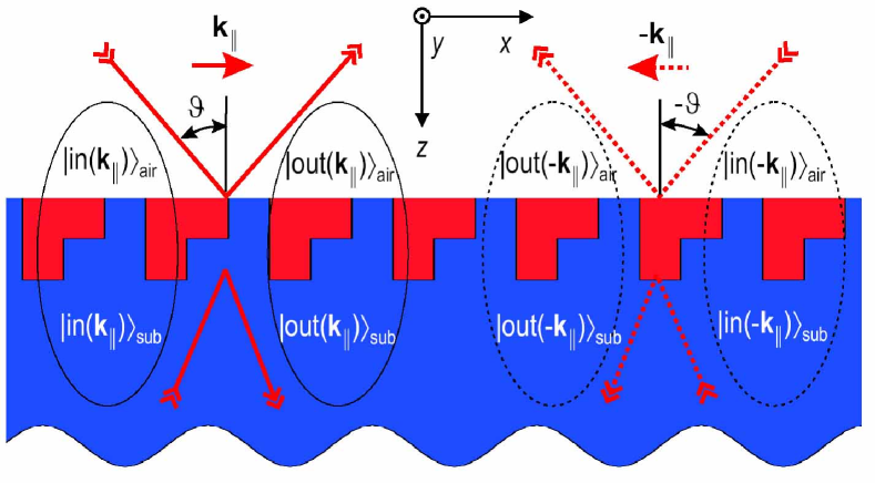
The symmetry of the system with respect to the time reversal in the case of PCS made of non-gyrotropic transparent materials [compare with Ref. Figotin and Vitebsky, 2001], means that for any solution of Maxwell equations for electric and magnetic fields, remains a valid solution. This property, as well known Landau and Lifshitz (1966), leads to the reciprocity between the input and output channels. In the definition of the unitary it makes sense to fix the ordering of the channels in such a way that the input channels in transfer into the output ones in and vice versa, upon time reversal, see a scheme in Fig.1. In the case of -polarisations basis, this can be written as endnote31
| (3) |
Note the important complex conjugates in Eq. (3). Then, the reciprocality of the unitary matrix means that endnote32
| (4) |
where ⊺ stands for the matrix transpose. The most general form of allowing for the time reversal can be then written as
| (5) |
where the input (output) orthogonal bases () and the scattering phases are functions of which are characteristic for the given PCS. The phases are actually even functions of , . Equation (5) means the existence of a special “diagonal” input and output basis sets, which do not mix up in the process of scattering.
It follows from Eq. (4) that, with the change of sign of in any asymmetric PCS, the reflection with linear polarisation conservation is always symmetric, ( is the amplitude reflection coefficient). Whereas the reflection with depolarisation from to (if exists) is asymmetric but equals to that from to , Simultaneously, the transmission (for ) with the conservation of linear polarisation from the air to substrate equals always to that in the inverse direction (for and from the substrate to air).
To the contrary, in the case of circular polarisations, because now the time reversal switches from to , the reflection with change of polarisation is symmetrical, Simultaneously, but the reflection with conservation of polarisation is asymmetrical, . Additionally,
These symmetry properties of the reflection (and transmission in reverse direction) are independent of how many diffraction channels are open. They are even more general and hold for PCS with absorptive materials, simply because any absorption channel can be included into a more general unitary S-matrix of the full system as an additional scattering channel. The symmetry of transmission in reverse direction is just what was found in Refs. Ebbesen et al. (1998); Ghaemi et al. (1998); Schroeter and Heitmann (1999). There is no contradiction here with the different field distributions, because the reciprocity exists between the time-reversal channels only. Whereas the full solution is not reciprocal, due to different reflected waves in the cases of incidence from the air and the substrate.
As to the symmetry of transmission for illumination from the same side of the PCS, in case of asymmetric PCS it holds at frequencies when all diffraction channels are closed, and only in transparent PCS, because the and transmission processes from the same side of the PCS are not reciprocal, see in Fig 1.
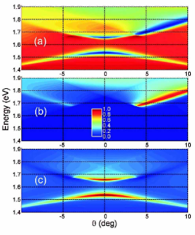
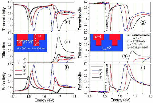
We give an example of such asymmetric optical response in Fig. 2(a-f) of a model transparent asymmetric 1D PCS, see the schematic crossection in panel (e). The incoming light is -polarised (electric field parallel to the PCS grooves). The calculations are done via -matrix method from Ref. Tikhodeev et al. (2002) using 21 harmonics in Eq. (1) with accuracy better than 10-3. Note that so far the diffraction is absent (for photon energy below 1.65 - 1.75 eV, depending on the angle of incidence) the transmissivity is symmetrical with the sign of . Note also that, in agreement with the discussion above, the reflectivity is always symmetric, see in panels (c,f).
The transmissivity dips in Fig. 2 are Wood’s anomalies Wood (1902); Fano (1941); Hessel and Oliner (1965) due to quasiguided modes in PCS. Near such resonances the reflectivity can become full in the zeroth diffraction order. Numerical examples of such a full reflectivity can be seen in Figs. 2c,f for normal incidence in asymmetric 1D PCS, and for any in a symmetric PCS, Fig. 2i. The full reflectivity is achievable unless the first diffraction channel opens, compare with panels (b,e,h).
These properties of the resonant reflectivity in transparent PCS can be deduced from the general properties of the unitary scattering matrix . Let has a zero at in the lower half of complex energy plane, corresponding to the guasiguided photonic mode Tikhodeev et al. (2002)
| (6) |
where is the resonant output eigenvector in the “large” basis. Here we analyse the simplest case of a nondegenerate quasiguided mode.
has to be unitary for real , and it imposes significant restrictions on its possible form. In fact, near the resonance one of the scattering phases (the resonant phase) is a quickly changing function of energy, and Eq.(5) can be rewritten in a form
| (7) | |||
| (8) |
where , i.e., the resonant “small” outgoing vector in the orthogonal basis corresponding to the “large” resonance vector , , and are the output basis vectors in the subspace orthogonal to . To ensure (the reciprocity of the reflection near the resonance), we have to set . However the resonant vectors and can be different if there is no additional symmetry of the structure transforming to . Equation (7) is the most general form of the Breit-Wigner formula (see, e.g., in textbook Landau and Lifshitz (1966)) for the resonant optical response in a transparent PCS. Except , all quantities in Eq. (7) are slow functions of ; neglecting this dependence gives a very good resonant approximation for in the vicinity of NAG .
In the zeroth diffraction order Eq. (7) can be simplified further. In this case is a matrix. However, in the case of 1D PCS, and for linearly polarised light with plane of incidence perpendicular to the grating grooves (), the and polarisations are decoupled. Then, becomes effectively a matrix. By a proper selection of the outgoing harmonics phases, the corresponding 2D vector can be made real, and
| (9) |
The most general form of the -dimensional unitary scattering matrix in this polarisation becomes
| (10) | |||||
where , and are slowly changing with parameters of the system near the resonance. For the coefficients of reflection and transmission we have, respectively
| (11) | |||
| (12) |
In the case of normal incidence () for any PCS, we have obviously that and, as a result,
| (13) | |||||
| (14) |
Obviously and at the energy when . Because is a slow function of energy, and makes a circumnutation from through to , this condition always matches at some energy near the resonance, provided is not too close to -1.
The quantity reaches its maximum at . Thus, the only possibility to reach a full transmission is to have and, as seen from Eq. (14), . For example, the full transmissivity is reached exactly at the resonance, , in the only case if and simultaneously. This is the case of a well known Fabry-Perot resonator with symmetrical lossless mirrors.
In asymmetric PCS, at oblique incidence, as can be understood from the inspection of Eq.(11), the reflectivity still peaks (or anti-peaks) near the resonance energy. However, now the maximum value of is obviously less than 1, because , i.e., the resonant vectors for the asymmetric PCS.
In case if the PCS has an additional symmetry transforming the input channels with to that with , we have . Then Eqs. (13,14) hold for any angle . As a consequence, the reflection can be full near the resonance for oblique incidence, not only for as in the asymmetrical gratings. This additional symmetry can be, e.g., a vertical mirror plane (symmetrical PCS on a substrate, see insert in Fig. 2e). The numerical examples shown in Fig. 2d-f fully agree with this analysis. We would like to add here that the property of full reflectivity is obviously destroyed by any losses, including absorption, defect and PCS edge scattering for finite sample size.
The resonant approximation neglecting slow dependences in Eqs. (11)-(14) gives a very good description of the optical response near the resonance, see an example in Fig. 2g-i. The parameters , and for any PCS can be calculated from the full scattering matrix NAG . This resonance approximation gives, e.g., a rigorous explanation of an intuitive model of the interference between direct and indirect pathways Fan and Joannopoulos (2002), with minimal number of directly calculated parameters (5 for general PCS, and 4 for normal incidence or symmetric PCS), and it is applicable for arbitrary PCS.
To conclude, using the unitarity and reciprocity properties of the scattering matrix, we analyze theoretically the nontrivial symmetry properties and near resonance behavior of the optical response in photonic crystal slabs (PCS) with asymmetric unit cell. As a direct consequence of the reciprocity, the reflection with conservation of linear polarisation is always symmetrical, whereas that with depolarisation, if exists, is asymmetrical. For the circularly polarised light the opposite rule holds. As a direct consequence of the unitarity, the PCS reflectivity peaks to unity near the quasiguided mode resonance for normal light incidence in the absence of diffraction, depolarisation, and losses. For the oblique incidence the full reflectivity in zero diffraction order is reached only in symmetrical PCS; in asymmetrical PCS the reflectivity maximum decreases with the angle of incidence increase.
Acknowledgements.
The authors are thankful for I. Avrutsky, L.V. Keldysh, and V.A. Sychugov for discussions. This work was supported in part by the Russian Foundation for Basic Research, Russian Ministry of Science, and Russian Academy of Sciences.References
- Maradudin and McGurn (1993) A. A. Maradudin and A. R. McGurn, J. Opt. Soc. Am. B 10, 307 (1993).
- Labilloy et al. (1997) D. Labilloyet al, Phys. Rev. Lett. 79, 4147 (1997).
- Astratov et al. (1999) V. N. Astratov et al, Phys. Rev. B 60, R16 255 (1999).
- Ebbesen et al. (1998) T. W. Ebbesen et al, Nature 391, 667 (1998).
- Ghaemi et al. (1998) H. F. Ghaemi et al, Phys. Rev. B 58, 6779 (1998).
- Fujita et al. (1998) T. Fujita et al, Phys. Rev. B 57, 12 428 (1998).
- Yablonskii et al. (2001) A. L. Yablonskii et al, J. Phys. Soc. Japan 70, 1137 (2001).
- Shimada et al. (2002) R. Shimada et al, IEEE J. Q. Electron. 38, 872 (2002).
- Wood (1902) R. W. Wood, Philos. Mag. 4, 396 (1902).
- Fano (1941) U. Fano, J. Opt. Soc. Am. 31, 213 (1941).
- Hessel and Oliner (1965) A. Hessel and A. A. Oliner, Appl. Opt. 4, 1275 (1965).
- Paddon and Young (2000) P. Paddon and J. F. Young, Phys. Rev. B 61, 2090 (2000).
- Ochiai and Sakoda (2001) T. Ochiai and K. Sakoda, Phys. Rev. B 63, 125107 (2001).
- Fan and Joannopoulos (2002) S. Fan and J. D. Joannopoulos, Phys. Rev. B 65, 235112 (2002).
- Tikhodeev et al. (2002) S. G. Tikhodeev et al, Phys. Rev. B 66, 045102 (2002).
- Ritchie et al. (1968) R. H. Ritchie et al, Phys. Rev. Lett. 21, 1530 (1968).
- Schroeter and Heitmann (1999) U. Schröter and D. Heitmann, Phys. Rev. B 60, 4992 (1999).
- Dykhne et al. (2003) A. M. Dykhne et al, Phys. Rev. B 67, 195402 (2003).
- Christ et al. (2003) A. Christ et al, Phys. Rev. Lett. 91, 183901 (2003).
- Fujita et al. (2000) T. Fujita et al, Physica E 7, 681 (2000).
- Nevière et al. (2000) M. Nevière et al, Electromagnetic resonances in nonlinear optics (Gordon and Breach ,2000). Here, a S-matrix is investigated as a function of the complex propagation constant. We prefer to follow a different definition of S as a function of complex energy, see in Tikhodeev et al. (2002).
- Golubenko et al. (1985) G. Golubenko et al, Kvant. Electron. 12, 1334 (1985).
- Mashev and Popov (1985) L. Mashev and E. Popov, Opt. Comm. 55, 377 (1985).
- Wang and Magnusson (1993) S. S. Wang and R. Magnusson, Appl. Opt. 32, 2606 (1993).
- Peng and Morris (1996) S. Peng and G. M. Morris, J. Opt. Soc. Am. A 13, 993 (1996).
- Porto et al. (1999) J. A. Porto et al, Phys. Rev. Lett. 83, 2845 (1999).
- García-Vidal and Martín-Moreno (2002) F. J. García-Vidal and L. Martín-Moreno, Phys. Rev. B 66, 155412 (2002).
- Figotin and Vitebsky (2001) A. Figotin and I. Vitebsky, Phys. Rev. E 63, 066609 (2001).
- Landau and Lifshitz (1966) L. Landau and E. M. Lifshitz, Quantum mechanics. Non-relativistic theory (Pergamon Press, 1966), ch.124,142.
- (30) We use conventional notations in which , so that .
- (31) . Using Eq. (3) . Thus, . Using unitarity , we arrive at Eq. (4).
- (32) N. A. Gippius, unpublished