On leave from ]B. Verkin Institute for Low Temperature Physics and Engineering, National Academy of Sciences of the Ukraine, 310164 Kharkov, Ukraine. On leave from ]Department of Solid State Physics, Comenius University, SK-84248 Bratislava, Slovakia.
Reading-out the state inductively
and microwave spectroscopy
of an interferometer-type charge qubit
Abstract
We implemented experimentally an interferometer-type charge qubit consisting of a single-Cooper-pair transistor closed by a superconducting loop that is in flip-chip configuration inductively coupled to a radio frequency tank circuit. The tank permits to readout the qubit state, acting as inductance measuring apparatus. By applying continuous microwave power to the quantum device, we observed inductance alterations caused by redistributions of the energy level populations. From the measured data, we extracted the energy gap between ground and upper levels as a function of the transistor quasicharge as well as the Josephson phase across both junctions.
pacs:
74.50.+r, 85.25.Am, 85.25.CpVarious quantum properties of superconducting structures with small Josephson tunnel junctions have been experimentally demonstrated by several research groups (see, e.g., Ref. Leggett, and references herein). The results have been widely discussed in literature because such devices might serve as prototypes for quantum bits (qubits).
In this context, the single-Cooper-pair transistor has attracted renewed attention. The device consists of two mesoscopic Josephson junctions coupled by a small island. The Hamiltonian of this system can be written asave
| (1) |
Here the first term on the r.h.s. is the charging energy of the island whereas the second one describes its Josephson coupling to the leads. The variable implies the number of excess Cooper pairs on the central electrode, the parameter is continuously controllable by the gate voltage via the capacitance . The one-electron Coulomb energy, , is expressed through the island’s sum capacitance . Furthermore, the coupling strength,
| (2) |
is a function of the total phase across both junctions, (being here a good quantum variable). are the individual Josephson energies and the respective junction phases. Note that the observable is conjugated to the island’s phase, . In order to realize charge qubits, we designed the system parameters to fulfill the domination, , of the Cooper pair Coulomb energy, , over the coupling strength .
In earlier studies, microwave induced transitions between ground and upper energy states in single-charge transistors were observed by measuring the switching currentjoy ; eil ; luk or by means of the photon-assisted quasiparticle currentNak . Later the quantum coherent oscillations in similar configurations have been detected by making use of microwave-pulsed readouts.NakamuraPashkinTsai ; Esteve
Recently, a new possible solution was theoretically proposed by several authors.Frie ; Zorin The main idea is to enclose a single-Cooper-pair transistor into a superconducting inductive loop forming an interferometer. The advantage of this circuit is its low dissipation and, therefore, the remarkably weak decoherence.Leggett For realizing the quantum measuring process, the loop is inductively coupled to a radio frequency tank circuit.
In this paper, we introduce experimentally the conception of an interferometer-type charge qubit in conjunction with a readout procedure managed by measuring the qubit’s reverse Josephson inductance,Zorin ; Krech
| (3) |
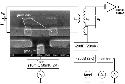
We put it into practice along the lines of the conventional impedance measuring techniqueRifkin by means of a high-quality tank inductively coupled to the interferometer loop. Based on this method, we present results of the spectroscopic investigation of the quantum device that is manipulated by a microwave field injected via a coaxial cable (UHF line, Fig. 1). These results demonstrate the utility of the used design relating to development and characterization (weak continuous quantum measuring) of future building blocks (coupled qubits) for quantum information circuits as well.
The principle of measurement is as follows: The expectation value is determined not only by the quasicharge (controlled by the gate voltage) and the phase (controlled by an external magnetic flux threading the interferometer loop) but also by the band index .ind Within the two-level approximation, the mean values in the upper state (=1) and in the ground state (=0) have the opposite sign,Krech . Consequently, a change of the band index results in a relevant impedance change that causes a shift of the tank resonance frequency.
Quantitatively, we consider only the case when the geometrical inductance of the loop is sufficiently small, ensuring in this way a unique relationship between the flux and the phase difference . This requirement can be expressed as follows within the two-band model, :Krech
| (4) |
where is the flux quantum and
| (5) |
is the local band spacing (with ). We emphasize the fact that the coupling strength and, therefore, the gap can be significantly reduced in the vicinity of the operating point =1, = even for relatively large ratios .
As discussed above, the observable takes different expectation values for the energy bands =0 and =1. Therefore, a redistribution of the level populations caused by microwave excitations (in competition with relaxation processes) results in a change of the quantum-statistical mean value . In order to prove this effect, the loop was coupled through a mutual inductance (where is the coupling coefficient) to the tank circuit (with known inductance and quality factor ). The tank is driven by an rf current at a frequency close to its resonance frequency . This current generates an rf flux threading the interferometer ring. Provided that, first, this rf flux is small, , and, second, the condition is fulfilled, variations of the interferometer inductance can be described by making use of the formulaIlichev01
| (6) |
where is the phase shift between drive current and tank voltage to be measured.
The used measurement setup is shown in Fig. 1. The Nb square-shaped pancake tank coil ( nH) was fabricated lithographically on an oxidized Si substrate. An external capacitance is used to complete the resonance circuit. This high-quality tank () is biased by the rf current at the resonance frequency of MHz. The rf voltage across the tank circuit was measured by means of a sequence of cold and room temperature amplifiers. The angular phase shift was determined using an rf lock-in voltmeter.

The qubit under investigation is placed in the middle of the coil in flip-chip configuration. The transistor was fabricated out of Al by the conventional shadow evaporation technique. The transistor’s gate line is filtered by means of three copper powder filters (with a total length of about 35 cm) at the temperatures 2 K, 50 mK and 10 mK. The attenuation of this line is about 120 dB at 5 GHz and 300 dB at 20 GHz. Microwave irradiation for photon-assisted excitations of the quantum device is fed into the sample via an UHF line consisting of a commercial coaxial cable from room temperature to 2 K as well as via a resistive coaxial cable (known as ThermoCoax) from 2 K to 10 mK. In order to reduce external interferences, two 20 dB commercial attenuators were installed at the temperature levels 2 K and 10 mK. The external magnetic flux applied to the interferometer loop is produced by a dc current through the tank coil. In order to feed both currents and into the tank, a simple bias tee is used (see Fig. 1).

The angular phase shift (6) was measured as a function of the gate voltage as well as of the dc current in the tank coil that generates the external flux . The coupling coefficient between tank and superconducting loop was obtained experimentallyIlichev01 to be . The mutual inductance is nH, and the geometrical loop inductance was calculated to be nH. Suitable adjusting the tank drive current permitted the qubit operation in the required small-signal limit, 10. The layout size of the junctions is 140 nm180 nm. Deviations from these nominal dimensions in the order of 10 (caused by the fabrication process) were estimated by means of the micrograph of the real structure. In accordance with this fact, the spectroscopically determined Josephson coupling energies showed a certain difference, GHz (see below). The measurements were performed in a dilution refrigerator at a nominal temperature of about 10 mK inside magnetic and superconducting shields.
In a first set of experiments, we investigated charging effects in the interferometer. Adjusting the external flux (), we fixed the phase () and measured the dependence of the statistical average (or , cf. Eq. 6) on the parameter . This dependence turned out to be rather weak due to the large ratio between Josephson and charging energies. Nevertheless, the coupling strength could be reduced down to GHz. Therefore, a variation of with was actually measurable for operating values of in the vicinity of . Indeed, the 2e-periodic oscillations of or with respect to the gate charge , explicitly demonstrating its quasicharge character, are clearly seen in Fig. 2 (bottom curve).Gotz
Small-amplitude continuous microwave irradiation of the sample varied significantly the obtained dependence: Now distinguished peaks appeared in the characteristics (upper curves in Fig. 2). Their positions depend on the frequency . Increasing microwave amplitudes led to a slight change of the peak width only. Thus we demonstrated that the peaks are originated by resonant excitations of the system from ground to upper states. (In general, the measured peaks disappeared at higher temperatures corresponding to the used frequency. For instance, for a peak induced by the frequency GHz, this temperature is about mK.) The microwave-induced transitions (at fixed parameters and ) from the ground to the upper states should correspond to specific values . Following this consideration and extracting the peak positions from the - curves measured at different microwave frequencies, we depicted the energy differences between ground and upper levels as a function of (Fig. 3). Then we fitted the spectroscopic data (analogously as reported in Ref. 8) by making use of the band gap (5) within the two-level approximation, providing GHz and GHz. (A fitting procedure by making use of a numerical treatment of the complete Hamiltonian (1) delivers practically the same values.)
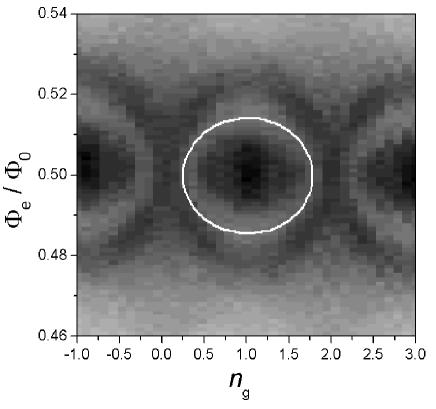
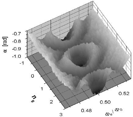
In further experiments, we measured the phase shift as a function of the applied magnetic flux in the vicinity of at varying gate voltage . At the same time, the microwave frequency was fixed. This way we obtained a spatial representation of the microwave-induced transitions as a function of both parameters and . The results for the microwave frequency of 8 GHz are presented in Fig. 4. Finally fitting the ring-shaped “crater rim” by means of the band spacing Eq. 5, we found spectroscopic data GHz and GHz for the junctions’ Josephson energies (cf. Fig. 5).
In conclusion, we have successfully implemented an alternative quantum two-level system in a superconducting circuit with readout. In this connection, we demonstrated the suitability of the Josephson quantum inductance term for developing a readout procedure. We performed a microwave spectroscopy of an interferometer-type charge qubit, making use of an rf tank readout. We reconstructed the energy gap between lower and upper energy levels as a function of the gate charge at fixed phase across the double junction. We demonstrated experimentally that the energy gap can be varied by changing both gate charge and external flux threading the interferometer loop. In view of the relatively large ratio , effects accompanied with the change of the gate charge were observed in the vicinity of = only. Our results indicate that the investigated qubit device is a potential candidate for realizing solid-state quantum processing in conjunction with weak characterization.
We thank A. Smirnov, A. Zagoskin, and A. Zaikin for fruitful discussions. We also would like to thank A.N. Omelyanchouk for comments and H. Mühlig for technical assistance. This work was partially supported by the Deutsche Forschungsgemeinschaft under contract No. KR 1172/9-2 and D-wave Sys. Inc.
References
- (1) A.J. Leggett, Science 296, 861, (2002).
- (2) D.V. Averin and K.K. Likharev, in Mesoscopic Phenomena in Solids, edited by B.L. Altshuler, P.A. Lee, and R.A. Webb (Elsevier, Amsterdam, 1991), p. 173, and M. Tinkham, in Introduction to superconductivity (McGraw-Hill, New York, 1996), 2nd ed., Chap. 7.
- (3) P. Joyez, P. Lafarge, A. Filipe, D. Esteve, and M. Devoret, Phys. Rev. Lett. 72, 2458 (1994).
- (4) T.M. Eiles and J.M. Martinis, Phys. Rev. B 50, 627 (1994).
- (5) D.J. Flees, S. Han, and J.E. Lukens, Phys. Rev. Lett. 78, 4817 (1997).
- (6) Y. Nakamura, C.D. Chen, and J.S. Tsai, Phys. Rev. Lett. 79, 2328 (1997).
- (7) Y. Nakamura, Yu.A. Pashkin, and J.S. Tsai, Phys. Rev. Lett. 87, 246601 (2001).
- (8) D. Vion, A. Aasime, A. Cottet, P. Joyez, H. Pothier, C. Urbina. D. Esteve, and M.H. Devoret, Science 296, 886 (2002). Especially, the authors report on band gap spectroscopy of a similar superconducting circuit (“quantronium”) that was performed by measuring the switching probabilities of interband transitions.
- (9) J.R. Friedman and D.V. Averin, Phys. Rev. Lett. 88, 050403 (2002).
- (10) A.B. Zorin, Physica C 368, 284 (2002).
- (11) W. Krech, M. Grajcar, D. Born, I. Zhilyaev, Th. Wagner, E. Il’ichev, and Ya. Greenberg, Phys. Lett. A 303, 352 (2002).
- (12) R. Rifkin and B.S. Deaver, Phys. Rev. B 13, 3894 (1976).
- (13) The band index can be related simply to the number of excess pairs on the island in the pure charge states (). Within the two-band model, this procedure leads to (lower state) and (upper state), respectively (cf. Ref. 7).
- (14) E. Il’ichev, V. Zakosarenko, L. Fritsch. R. Stolz, H.E. Hoenig, H.-G. Meyer, M. Götz, A.B. Zorin, V.V. Khanin, A.B. Pavolotsky, and J. Niemeyer, Rev. Sci. Instr. 72, 1882 (2001).
- (15) Measurements of ground band properties of a similar system were reported by M. Götz, S.A. Bogolovsky, and A.B. Zorin, in Tagungsband 8th Statusseminar BMBF Feb. 13-14, 2003, Garmisch-Partenkirchen (VDI Technologiezentrum, Düsseldorf, 2003), p. 50.