Optical pumping NMR in the compensated semiconductor InP:Fe
Abstract
The optical pumping NMR effect in the compensated semiconductor InP:Fe has been investigated in terms of the dependences of photon energy (), helicity (), and exposure time () of infrared lights. The 31P and 115In signal enhancements show large asymmetries and anomalous oscillations as a function of . We find that (i) the oscillation period as a function of is similar for 31P and 115In and almost field independent in spite of significant reduction of the enhancement in higher fields. (ii) A characteristic time for buildup of the 31P polarization under the light exposure shows strong -dependence, but is almost independent of . (iii) The buildup times for 31P and 115In are of the same order ( s), although the spin-lattice relaxation times () are different by more than three orders of magnitude between them. The results are discussed in terms of (1) discrete energy spectra due to donor-acceptor pairs (DAPs) in compensated semiconductors, and (2) interplay between 31P and dipolar ordered indium nuclei, which are optically induced.
pacs:
76.60.-k, 32.80.Bx, 76.70.Fz, 78.30.Fs, 03.67.LxI Introduction
A solid-state NMR quantum computer has attracted much attention because of its great potential as a scalable quantum computer, DiVincenzo (1995); Yamaguchi and Yamamoto (1999); Goto et al. (2002a); Ladd et al. (2002); Goto et al. (2002b, 2003a) but it holds the problem of extremely low efficiency in initialization and readout processes due to low nuclear spin polarization at thermal equilibrium. One of the possible resorts to resolve it is an optical pumping NMR in semiconductors, Shimizu (2000); Ladd et al. (2002); Goto et al. (2003a) which provides an aligned nuclear spin system inside a semiconductor through transfer of angular momenta from photons to nuclei via electrons. Lampel (1968); Meier and Zakharchenya (1984) The aligned nuclei can be used as an initial state of the pseudo-pure technique for initialization Gershenfeld and Chuang (1997) as well as for a signal enhancement for readout. Moreover, such a semiconductor can be used as a reservoir of the spin polarization, which is transferred to nuclear spins in another material that serves as a quantum computer. Tycko (1998) The scheme is specifically called an optical pumping qubit initializer (OPQI).Goto et al. (2003a, b) It allows us to separate initialization process from computation, so that the latter can be optimized independently of the former.
The OPQI requires a polarizer (reservoir) with the following characteristics; (1) high optical pumping efficiency, (2) large nuclear moment and (3) high spin transfer efficiency from the polarizer to a polarized material.Goto et al. (2003b); Tycko (1998) Among many semiconductors, indium phosphide (InP) is expected to possess preferable characteristics at least for (2) and (3), i.e., 31P has 100% abundance and a high nuclear gyromagnetic ratio = 17.235 MHz/T, which enables us to retain high nuclear spin moments. Moreover, since the nuclear spin of 31P () is 1/2, no quadrupolar broadening of the 31P spectrum exists at an interface, which reduces a chance of degrading the polarization transfer efficiency.
It is known, however, that InP has problems in (1); it shows rather complicated optical pumping effects, which prevents us from optimizing the enhancement of 31P polarization. It shows strong dopant dependence, and clear enhancement of a 31P NMR signal has been reported only in undopedTycko (1998); Patel et al. (1999) and Fe-doped samples.Michal and Tycko (1999); Hashi et al. (2003); Goto et al. (2003c) Moreover, a Fe-doped sample, which shows the most significant enhancement, exhibits rather peculiar and unique optical pumping behaviors such as, (i) an oscillatory behavior of the 31P enhancement against a photon-energy () of an incident light, (ii) an asymmetric enhancement in terms of a photon-helicity (right- and left-circular polarizations, ),Michal and Tycko (1999) and (iii) single resonance polarization transfer from 115In to 31P with only a rf-field for 31P. Michal and Tycko (1998) In order to optimize the 31P enhancement in InP, it is inevitable to understand the mechanism of these behaviors and gain information about guiding principle for an effective optical pumping.
In this paper, we report on optical pumping effects in InP:Fe in terms of , and light exposure time () dependences under the various experimental conditions of magnetic field and temperature. The results are discussed in terms of the unique characteristics of this system, with which the conditions for the effective optical pumping in InP are discussed.
II Optical pumping NMR in III-V semiconductors
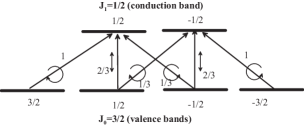
Here, we summarize an optical pumping NMR in III-V semiconductors. Primarily, the optical pumping effect is caused by a transfer of angular momenta from incident photons to nuclei via electrons. Photons with have the angular momenta , which pump up the electrons from the heavy- and light-hole bands to the conduction band by adding (subtracting) an angular momentum of to the electron spins, as shown in Fig. 1.Meier and Zakharchenya (1984) Due to the difference in the transition probabilities, the excess electrons with either spin-up or down states are created by , depending on the sign of the electron g-factor. The z-component of the photoexcited electron spin thus created is relaxed with an electron spin relaxation time . In the steady state, a net spin is given by,
| (1) |
where corresponds to at the instant of the photon-absorption, and is the lifetime of the photoexcited electrons.
The spin polarization is transferred to nuclei. ( stands for an spatial average over a region large enough compared to the lattice spacing .) The nuclear spin polarization is given by,
| (2) |
where with
| (3) |
being the electron spin at thermal equilibrium at . In the optical pumping experiments,
| (4) |
because , i.e., the average nuclear polarization is proportional to that of the electron spins. Note that in the Overhauser effect because .
The dynamics of the polarization is given through hyperfine couplings with the pumped electrons trapped in trapping sites. The light exposure time dependence of is given by,Kuhns et al. (1997); Patel et al. (1999)
| (5) |
where is the spin-lattice relaxation time in the dark, and is the cross relaxation time between electrons and nuclei. In the case of a Fermi contact type interaction, is given by,Kuhns et al. (1997); Patel et al. (1999)
| (6) |
Here, is a hyperfine coupling constant, is a correlation time for exchange of electrons between the conduction band and the trapping sites, and and are the nuclear and electron Larmor frequencies, respectively. Since and S=1/2, Eq. (6) is reduced to,
| (7) |
A contact type interaction is expected to be dominant in the case of shallow donors, because polarized electrons directly interact with nuclei of order , and because in Eq. (6) is short due to the frequent hopping of electrons between the conduction band and the trapping sites. In the case of deep impurity centers, on the other hand, the carriers are localized so that a dipolar type hyperfine coupling rather than the contact type plays a dominant role. In this case, non-secular terms in the dipolar hyperfine coupling such as and are dominant. Since no spin flips of electrons are needed in this process, the energy mismatch between and is of no importance.
The nuclear polarizations, created either by the Fermi contact or the dipolar hyperfine couplings, are transmitted to the region far from the impurity center via the spin diffusion process with homo-nuclear dipolar interactions. In the dilute limit, the diffusion process is described by,
| (8) |
where is a spin polarization at thermal equilibrium, which is small compared to in the optical pumping process. is a spin diffusion constant caused by homo-nuclear dipolar couplings, which is of the order of with being the probability of a flip-flop process between nearest homo-nuclear spins. is a numerical factor, which is 1 for the Fermi contact case and 1/2 for the dipolar coupling case. If is neglected and , the steady state solution of Eq. (8) is given by,
| (9) |
If a leakage by can be ignored (), Eq. (9) is reduced to Eq. (4).
III Experimental details
In this section, we describe the experimental setup used in this study.Goto et al. (2003c) A Ti:Sapphire tunable laser pumped by a diode-pumped Nd:YVO4 cw green laser is used to produce a linearly polarized light with the wavelength between 850 and 1050 nm. The lights are delivered to the tip of an NMR probe in a cryostat installed in superconducting magnets (6.347 T and 11.748 T) by a polarization-maintaining (PM) single mode optical fiber (Fujikura), which transmits a light with its linear polarization maintained. A quarter-wave plate is attached to the tip of the NMR probe, which converts the linearly polarized light to the circular one. The helicity of the circularly polarized light () can be changed by a half-wave plate located on the optical table before the light is introduced into the fiber.
The samples used were commercially available InP wafers doped with Fe (Showa Denko Co. Ltd.). We also used three other samples (nominally undoped, and doped with S, Zn) as references. The InP wafers 350 m thick were cut into 5 8 mm rectangular shapes and mounted on the NMR probe with the surfaces (100) normal to the magnetic field. The samples were wound by a copper wire, which served as a detection coil. The circularly polarized lights were illuminated to the samples through the aperture of the coil. The diameter of the illuminated spot was about 5 mm. NMR signals of 31P were detected at temperatures between 4 and 40 K by a pulsed NMR spectrometer with the pulse sequence of comb (64 -pulses)-- pulse-FID, where the first 64 comb pulses extinguished a nuclear magnetization, and that built up by the infrared lights during the exposure time of was detected by a free induction decay signal. The dark experiment was performed with the same pulse sequence but without laser irradiation, where , instead of , corresponds to the long delay time in the saturation recovery experiments.
IV Results
IV.1 Roles of dopants
Before detailed experiments on InP:Fe, we examined the optical pumping effects of 31P in InP with four different dopants, which are summarized in Table 1 along with their basic properties provided by the manufacturer. Among the four dopants, only Fe shows a clear optical pumping effect. The nominally undoped sample shows a weak effect, while little effects are observed in the S and Zn doped samples. Also shown in Table 1 are ’s of 31P in the dark, which exhibits a correlation with the optical pumping effect, i.e., more intense effect is observed for the dopants with longer of 31P. The qualitative explanations for these results can be given as follows;
| dopant | carrier | (cm-3)111 Carrier density at 300 K. | (s)222 of 31P at 4.2 K. | optical pumping |
|---|---|---|---|---|
| Zn | p | 100 | no | |
| S | n | 130 | no | |
| undoped | n | 1300 | weak | |
| Fe | S-I333 S-I: Semi-insulator | intense |
(1) Zinc-doped sample: type carriers with relatively high density. In general, of holes in the valence bands is very short because a strong spin-orbit coupling makes coupled tightly to the momentum relaxation time . Moreover, exchange interactions between holes and electrons cause a short of the pumped electrons (Bir-Aronov-Pikus mechanism).Meier and Zakharchenya (1984) Eq. (1) predicts that the short gives rise to little optical pumping effects.
(2) Sulfur-doped sample: type carriers with relatively high density. This sample has a relatively short due to the hyperfine interaction of a Fermi contact type between trapped electrons and 31P. The spin polarization of 31P leaks away at the rate of . This results in and is reduced to zero, as indicated in Eq. (9).
(3) Nominally undoped sample: type carriers with relatively low density. The of 31P is relatively long due to the low carrier density, and a weak optical pumping effect is observed.
(4) Iron-doped sample: a compensated semiconductor whose carrier density is extremely small. The low carrier density causes a very long and the polarization transferred from the optically pumped electrons are accumulated in the 31P nuclei.
IV.2 Optical pumping NMR in InP:Fe
IV.2.1 Temperature and light exposure time dependences of the 31P signal enhancement
In what follows, we will restrict ourselves to the case of InP:Fe, where the most intense optical pumping effect is observed. Figure 2 shows the 31P NMR spectra of InP:Fe under light irradiation (power density =430 mW/cm2), together with that in the dark case. The absolute value of the integrated spectral intensity is enhanced for either helicity, but the phase of the signal for is shifted by 180o (negative) from the dark case. The negative enhancement for suggests that a hyperfine coupling is of dipolar origin.Patel et al. (1999)

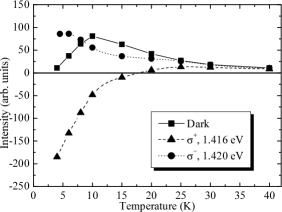
Figure 3 shows the temperature dependence of the integrated 31P signal intensity with = 430 mW/cm2 and s, together with that in the dark case with s. The enhancement is more significant at lower temperature because of a long there. In general, it is expected that decreases by a few orders of magnitude from 4.2 K to 300 K, while the lifetime increases only slightly in the same temperature range. From our data, the crossover temperature, above which and in Eq. (1), is estimated to be about 30 K. A peak around 10 K observed in the dark case is due to , which increases quite rapidly below 10 K.
| (eV) | Helicity | (s) |
|---|---|---|
| 1.420 | 2.9 0.2 | |
| 2.6 0.2 | ||
| 1.416 | 4.7 0.2 | |
| 4.6 0.2 |
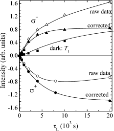
Figure 4 shows the exposure time () dependence of the integrated 31P signal intensity for at 1.416 eV and for at 1.420 eV, where the maximal enhancement is observed for each helicity. Since the light is illuminated only at a part of the sample, the observed signal is the sum of the contributions from the illuminated and the dark regions of the sample. The real dependence in the illuminated region can be derived by subtracting that in the dark from the observed data, which are shown by closed triangles and circles in Fig. 4. The buildup times () obtained by single exponential fits to the corrected data are shown for the two different and the helicities in Table 2. One finds that the buildup time is independent of the helicity within the experimental error.
The maximal enhancement factor of the 31P signal can be estimated from Fig. 4 by taking into account the buildup time as well as the volume of the illuminated region. Here, we define the normalized signal enhancement as follows.
| (10) |
where and are the integrated signal intensity measured under the light irradiation with and , and that of the background measured in the dark with , respectively. The subtraction of in the numerator allows us to extract only the contribution from the illuminated region of the sample. From Fig. 4, , while the area of the illuminated spot is 0.4 of the total area of the sample. Since the penetration depth of the light at 1.42 eV is 2 m Michal and Tycko (1999), the total volume where the optically pumped nuclei are involved is about 0.2 % of the whole sample. Hence, the enhancement factor for 1.416 eV and is . Since of 31P at thermal equilibrium at 4.2 K is 6.3 , the average polarization of 31P nuclei in the illuminated region is estimated to reach about 40 %.
IV.2.2 Photon energy dependence of the 31P signal enhancement
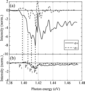
Figure 5(a) shows the dependences of the 31P signal enhancements s) with = 430 mW/cm2 at 4.2 K and 6.347 T. Here, one can see oscillatory behaviors of as a function of . One may also notice that is quite asymmetric in terms of helicity, i.e., . In particular, (1.416 eV, ) is negative as is (1.416 eV, ). These behaviors cannot be accounted for by the picture given in §II.
We also performed the same experiment at 11.748 T, which is shown in Fig. 5 (b). One can see that the absolute value of the enhancement is reduced by a factor of 4 from that in Fig. 5 (a). The factor “4” is consistent with Eqs. (7) and (9) in that and that is increased by 1.85 from 6.347 T to 11.748 T. Note that the field dependence of the signal intensity irrelevant to the optical pumping effect is canceled out by the denominator in Eq. (10). On the other hand, the oscillation period as a function of is the same for both the fields, i.e., the local maxima and the minima appear at the same ’s.
IV.2.3 Photon energy dependence of the 115In signal enhancement
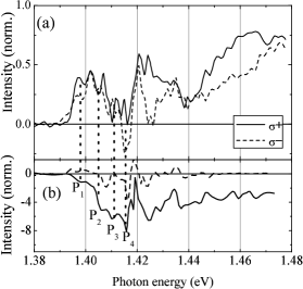
Fig. 6(a) shows the dependences of the enhancement s) for 115In at 4.2 K and 6.347 T with =430 mW/cm2. For comparison, the data for 31P [Fig. 5(a)] are shown in Fig. 6 (b). Here, one can find the following features for the 115In signal enhancements in this figure. (1) The signal enhancements are positive for both the and except for at around P4. (2) The difference between and is less significant than that for 31P. (3) The signal enhancements also show oscillatory behaviors as seen in the case of 31P. (4) The oscillation period is almost the same between 115In and 31P, but they are out-of-phase, i.e., the local minima for 115In indicated by Pi coincide with the negative maxima for 31P. Again, these features cannot be explained by the theory in §II, indicating that the enhancement may be subject not only to the spin-selective interband transitions and hyperfine couplings, but also to some other mechanism.
A rather unexpected behavior has been also observed in the buildup times. Table 3 shows the buildup times for 31P and 115In at 4.2 K with = 1.420 eV along with the values at 300 K. One can see that the buildup times are of the same order between 115In and 31P. This result is unexpected because the values are different by more than three orders of magnitude between them. To see how it is unexpected, let us estimate the ratio of the buildup times between 115In and 31P (i.e., ) expected from that of the values. From Eq. (7),
| (11) |
while can be estimated from the values because .
| (12) |
where 31I=1/2 and 115I=9/2 are the nuclear spins for 31P and 115In, respectively. From Table 3,
| (13) |
so that is estimated to be . This is inconsistent with the fact that are of the same order for 31P and 115In. We will address these unexpected results in the next section.
| 115In | 31P | ||
| (s) | |||
| (s) | - | 1.0 0.1 | 5.1 0.2 |
V Discussion
The most peculiar aspect of the optical pumping effects in InP:Fe is the oscillatory behaviors of the signal enhancements as a function of . Michal et al. discussed its possible relation with the electron momentum relaxations caused by LO-phonons with discrete energy levels, but they found that the oscillation period did not match that estimated for the LO-phonons.Michal and Tycko (1999) Since this behavior is not observed in the undoped InP,Farah et al. (1998) some unique properties of the InP:Fe sample may be responsible for it. We speculate, from the data shown in the previous sections, that it stems from the structures of the photon absorption spectrum rather than relaxations.
Here, we divide this oscillation into two parts; i.e., the regions below and above P4 in Fig. 5. The oscillation below P4 may be caused by traps associated with phosphorus vacancies and Fe-ions. The former exists even in the undoped InP, while the latter results from Fe-doping, which compensates the electrons caused by the former. In fact, the peaks in this region can be assigned from the photoluminescence (PL) peaks reported in Ref. Kuriyama et al., 1994. For example, = 1.417 eV, labeled as P4 can be assigned to the band edge transition, while P1 (=1.396 eV) to excitons bound to deep level acceptors. The two peaks between P1 and P4 (P2, =1.407 eV and P3, 1.412 eV) have been also observed in the PL spectrum, which may be related to excitons bound to neutral donors and/or acceptors.Kuriyama et al. (1994)
The oscillation above P4, on the other hand, may be associated with the defect-acceptor or donor-acceptor pairs (DAP) in InP:Fe.Kuriyama et al. (1994) The process of a photo excitation in a DAP is described as,
| (14) |
and the transition energy is given by,
| (15) |
where , , and are the energy for the gap energy and the binding energies in a neutral donor and an acceptor (D0 and A0), respectively. The last term in Eq. (15) represents the coulomb binding energy () between the donor and the acceptor, where is a distance from the donor of interest to the acceptor at the -th nearest neighbor shell and is a dielectric constant, which is 9.6 in InP.Sahu et al. (1991) Since the donor and the acceptor sites are localized at lattice points, can take only discrete values determined by the crystal structure and the lattice constant . This results in discrete levels, and shows a series of discrete transition peaks. The optical pumping effects with different occur in different DAPs, and these discrete levels manifest themselves as the oscillatory behavior of the NMR signal enhancement through in Eq. (6). The energy difference in between adjacent shells () falls within the range from 1 to 10 meV for ,Thomas et al. (1964) which are comparable to the oscillation period of the signal enhancements above P4 in Figs. 5 and 6. We expect that the density of such accepter and donor pairs could be of the order of cm-3, because the undoped InP sample contains donor sites of the order of cm-3, which are compensated by acceptors caused by the Fe-doping.
Let us turn to the issue of the asymmetry manifested in Fig. 5. The asymmetry indicates that the polarization is not directly determined by in Eq. (1). On the other hand, the buildup time shown in Table 2 is almost independent in spite of the large asymmetry of the enhancements. These facts suggest that, besides the usual optical pumping process by photons, there may be another process for buildup of the 31P polarization, which is independent of the photon helicity. The buildup process may be described phenomenologically (neglecting in the dark) as,
| (16) |
where and are the cross relaxation times of 31P by trapped electrons and by some unknown (second) process, respectively, and and are the corresponding polarizations at . Here, is negative (positive) for (), while is always negative regardless of . Note that , , and may be all dependent. If , is predominated by the second process.
A plausible mechanism for this second process is that caused by the dipolar ordered 113/115In nuclei, as manifested by the single resonance polarization transfer effect.Michal and Tycko (1998) This effect is caused by the Hartmann-Hahn cross-polarization mechanism between 31P nuclei in the rotating frame and dipolar ordered 113/115In nuclei in the laboratory frame. In the dipolar ordered state, 113/115In nuclei form domains in which the nuclei are correlated by nuclear dipolar couplings. Anderson and Hartmann (1962) The energy required to flip a spin of the domain is not only a Zeeman energy of one nucleus , but also of the order of nuclear dipolar-dipolar interactions because of the strong nuclear spin correlations (in other words, multiple quantum coherences) in each domain. We may expect that a similar mechanism renders reorientation of 31P by the dipolar ordered indium nuclei.
Here, one may pose a question: i.e., provided that 113/115In are responsible for the second process (), how can we expect the phenomenon similar to the single resonance nuclear polarization transfer, although neither 31P nor 113In are in the resonance condition during the light exposure? We consider that the reorientation of 31P is caused by the dynamic nuclear self-polarization, where 31P nuclei interact indirectly with 113/115In nuclei via electrons. Dyakonov and Perel (1972); Meier and Zakharchenya (1984); Farah et al. (1998) The mechanism is as follows. The polarization of nuclei created by the optical pumping produces nuclear magnetic fields for electron spins, which causes net electron spin in Eq. (1) to change. Simultaneously, the change in gives rise to the change in the nuclear polarization as given by Eq. (4), and as a result, the interactions among 113In, 115In and 31P are set up.
Note that this process is different from the usual indirect nuclear spin-spin coupling, e.g. the Suhl-Nakamura interaction in magnets, where electron spins appear in the process only implicitly as a virtual process, so that the energy conservation between the nuclear spins is strictly observed. In the present process, on the other hand, changes in the electron spins are not virtual but actual. The influence of the electron spins on the nuclei manifests itself as a static internal field, and the difference in the Zeeman energies between 31P and 113/115In could affect only a dynamical aspect of the process through given by Eq. (6). In the present case, however, , so that of 31P may not be a determinant of . Since the process proceeds in a cooperative way among 113In, 115In and 31P nuclei via the net electron spins , the same order of is anticipated for 115In and 31P, which is what we have actually seen in Table 3.
We believe that these mechanisms are rather plausible. Nevertheless, further investigations are needed to elucidate these peculiar behaviors.
VI Conclusion
We have investigated the optical pumping NMR in InP:Fe, which exhibits the most intense optical pumping effect among other dopants. The effect has been optimized and the 31P polarization up to about 40 % has been achieved with and = 1.416 eV.
The quite effective optical pumping effect in InP:Fe is accompanied by some peculiar phenomena such as the oscillatory behavior of the NMR signal enhancement as a function of and the asymmetry of the enhancement against . We have revealed that the buildup time for the 31P enhancement is almost independent of the helicity, and has the same order as that of 115In. These results indicate that the buildup process of 31P polarization is not determined by the usual optical pumping process by photon absorption. We have discussed the possible reorientation of the 31P nuclei due to the indirect couplings with the dipolar ordered 113/115In polarizations via trapped electrons. On the other hand, the magnetic-field and nucleus (31P and 115In) independence of the oscillation period suggests that the oscillation is caused by traps at phosphorus vacancies and/or donor-acceptor pairs (DAP), which provide a discrete photo-excitation spectrum.
The present work has shown that the optical pumping NMR is an effective tool for the investigations of impurity levels in semiconductors.
Acknowledgments
The authors would like to acknowledge helpful advice by M. Oshikiri. One of the authors (A. G.) is also indebted to R. Tycko for helpful discussion. This work has been partially supported by Industrial Technology Research Grant Program in ’03 from New Energy and Industrial Technology Development Organization (NEDO) of Japan.
References
- DiVincenzo (1995) D. DiVincenzo, Phys. Rev. A 51, 1015 (1995).
- Yamaguchi and Yamamoto (1999) F. Yamaguchi and Y. Yamamoto, Appl. Phys. A: Matter. Sci. 68, 1 (1999).
- Goto et al. (2002a) A. Goto, T. Shimizu, R. Miyabe, K. Hashi, H. Kitazawa, G. Kido, K. Shimamura, and T. Fukuda, Appl. Phys. A: Matter. Sci. 74, 73 (2002a).
- Ladd et al. (2002) T. D. Ladd, J. R. Goldman, F. Yamaguchi, Y. Yamamoto, E. Abe, and K. M. Itoh, Phys. Rev. Lett. 89, 017901 (2002).
- Goto et al. (2002b) A. Goto, T. Shimizu, and K. Hashi, J. Phys. Soc. Jpn. 71, 2125 (2002b).
- Goto et al. (2003a) A. Goto, T. Shimizu, K. Hashi, H. Kitazawa, and S. Ohki, Phys. Rev. A 67, 022312 (2003a).
- Shimizu (2000) T. Shimizu, Proc. Quantum Information Technology Workshop (Atsugi, Japan, 2000).
- Lampel (1968) G. Lampel, Phys. Rev. Lett. 20, 491 (1968).
- Meier and Zakharchenya (1984) F. Meier and B. P. Zakharchenya, eds., Optical Orientation, vol. 8 of Modern Problems in Condensed Matter Science (North Holland, Amsterdam, 1984).
- Gershenfeld and Chuang (1997) N. A. Gershenfeld and I. L. Chuang, Science 275, 350 (1997).
- Tycko (1998) R. Tycko, Sol. State Nuc. Mag. Res. 11, 1 (1998).
- Goto et al. (2003b) A. Goto, K. Hashi, T. Shimizu, X. Wen, S. Ohki, T. Iijima, and G. Kido, J. Magn. Magn. Mat. in press (2003b).
- Patel et al. (1999) A. Patel, O. Pasquet, J. Bharatam, E. Hughes, and C. R. Bowers, Phys. Rev. B 60, R5105 (1999).
- Michal and Tycko (1999) C. A. Michal and R. Tycko, Phys. Rev. B 60, 8672 (1999).
- Goto et al. (2003c) A. Goto, R. Miyabe, K. Hashi, T. Shimizu, G. Kido, S. Ohki, and S. Machida, Jpn. J. Appl. Phys. Pt. 1 42, 2864 (2003c).
- Hashi et al. (2003) K. Hashi, A. Goto, R. Miyabe, T. Shimizu, G. Kido, S.Ohki, and S. Machida, Physica B 329-333, 1235 (2003).
- Michal and Tycko (1998) C. A. Michal and R. Tycko, Phys. Rev. Lett. 81, 3988 (1998).
- Kuhns et al. (1997) P. L. Kuhns, A. Kleinhammes, T. Schmiedel, W. G. Moulton, P. Chabrier, S. Sloan, E. Hughes, and C. R. Bowers, Phys. Rev. B. 55, 7824 (1997).
- Farah et al. (1998) W. Farah, M. Dyakonov, D. Scalbert, and W. Knap, Phys. Rev. B 57, 4713 (1998).
- Kuriyama et al. (1994) K. Kuriyama, K. Tomizawa, M. Kashiwakura, and K. Yokoyama, J. Appl. Phys. 76, 3552 (1994).
- Sahu et al. (1991) T. Sahu, K. Nayak, and R. N. Acharya, Phys. Rev. B 44, 1922 (1991).
- Thomas et al. (1964) D. G. Thomas, M. Gershenzon, and F. A. Trumbore, Phys. Rev. 133, A269 (1964).
- Anderson and Hartmann (1962) A. G. Anderson and S. R. Hartmann, Phys. Rev. 128, 2023 (1962).
- Dyakonov and Perel (1972) M. I. Dyakonov and V. I. Perel, JETP Lett. 16, 398 (1972).