Paramagnetic anisotropic magnetoresistance in thin films of SrRuO3
Abstract
SrRuO3 is an itinerant ferromagnet and in its thin film form when grown on miscut SrTiO3 it has of K and strong uniaxial anisotropy. We measured both the Hall effect and the magnetoresistance (MR) of the films as a function of the angle between the applied field and the normal to the films at temperatures above . We extracted the extraordinary Hall effect that is proportional to the perpendicular component of the magnetization and thus the MR for each angle of the applied field could be correlated with the magnitude and orientation of the induced magnetization. We successfully fit the MR data with a second order magnetization expansion, which indicates large anisotropic MR in the paramagnetic state. The extremum values of resistivity are not obtained for currents parallel or perpendicular to the magnetization, probably due to the crystal symmetry.
I Introduction
The phenomenon of anisotropic magnetoresistance (AMR) in magnetic conductors expresses the dependence of the resistivity on the angle between the current and the magnetization . In polycrystals the AMR effect is commonly found to follow: where is the resistivity when , and is the resistivity when AMR . This simple relation is not expected to hold in crystalline samples where both the current orientation relative to the lattice as well as the magnetization orientation relative to the lattice play an important role.
Here we present AMR measurements of thin films of the d itinerant ferromagnet SrRuO3 above ( K). Those films are epitaxial and characterized by large uniaxial magnetocrystalline anisotropy (MCA) easy axis . In our measurements, we study the AMR in uncommon conditions: (a) while in most AMR measurements the orientation of is changed without changing its magnitude, here, because of the large MCA both orientation and magnitude of are changing; and (b) while in most AMR measurement the applied field is parallel to , here, because of the large MCA except for the cases where is along the easy or hard axes. Therefore, to explore the AMR in SrRuO3 it is not sufficient to measure magnetoresistance (MR) as a function of angle, but we need to independently determine both the magnitude and orientation of .
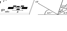
Our films are grown on miscut () SrTiO3 substrates using reactive electron beam epitaxy. The films have orthorhombic structure ( Å, Å, Å) and they grow uniformly (without twinning) with the axis in the film plane and the and axes at out of the plane (see Fig. 1) Marshall . The MCA is uniaxial with the easy axis along the axis and thus the uniform growth of the measured films can be confirmed by MR measurements in the ferromagnetic phase angle . The films were patterned by photolithography to allow Hall effect (HE) and MR measurements. The sample whose results are presented here is Å thick with K and resistivity ratio of .
II Measurements and discussion
Our measurements have two parts: (a) extraordinary Hall effect (EHE) EHE measurements from which we extract both the magnitude and the orientation of , and (b) MR measurements for currents in the and directions. Combining the two measurements we show that the MR can be fit very well with a second order magnetization expansion.
Both HE and MR measurements were performed as a function of the angle between the applied field and the easy axis, where is rotating in the plane. Each film has two kinds of patterns: a pattern with current along the direction (denoted Pab) and a pattern with current along the direction (denoted Pc). While in Pab the angle between and varies with , in Pc the field is always perpendicular to . The measurement configuration is illustrated in Fig. 1.
The Hall field in magnetic conductors has two contributions:
where is the magnetic field, and and are the ordinary and the extraordinary Hall coefficients, respectively. By measuring the HE in our films at a temperature where vanishes rs we determined , which enabled to extract (where is the component of which is perpendicular to the film plane) at all temperatures. This is not sufficient, however, since we need to determine both components of . For that we note that based on symmetry considerations we may assume that if a field , that is applied in the plane at an angle relative to the easy axis, creates a magnetization pointing at an angle relative to the easy axis, then applying the same field at an angle will create the same magnetization, but at an angle demag . In our case the easy axis is at out of the plane thus symmetry considerations yield that where and are the in-plane and perpendicular components of , respectively. Consequently, by measuring the Hall resistivity () at and we obtain: and , which allows to determine (multiplied by ). Figures 2a and 2b show the change in the magnitude and direction of as a function of at K determined with that method. As expected, obtains its maximum value at and lags behind except for along and . It seems that this is the first time that EHE which is sensitive only to the perpendicular component of the magnetization is used for extracting the full magnetization vector based on symmetry consideration. This is possible only due to the tilted easy axis. Where the easy axis is perpendicular or parallel to the film this scheme is not applicable.
Figures 2(c) and 2(d) present the MR measured at K for T and T in Pab and Pc. To fit the MR data we expand MR in , noting that due to the MR symmetry under field inversion the lowest order expansion is of second order. Since in our experiment remains in the plane it is sufficient to use two components of . We use the freedom of choosing the principle axes to take them in the crystallographic directions of and . Therefore, the general expansion of the MR to lowest order is:
| (1) |
where and are the components of along the easy axis () and hard axis (), respectively. The lines in Figs. 2(c) and 2(d) are fits of the MR data based on the measured and Eq. 1.
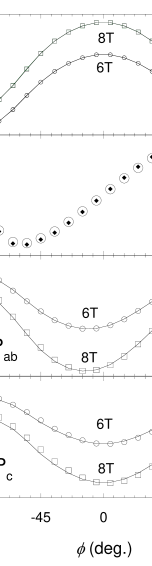
We obtained the following fitting parameters at K: , for the Pab pattern, and , for the Pc pattern. The error limits indicate the evaluated changes in the fitting parameters in case there is difference between the instrumental and the actual of up to .

The fits of the MR data based on Eq. 1 allow us to determine the ”clean” AMR effect; namely, how would the resistivity change if we could rotate in the plane without changing its magnitude. Figure 3 shows the expected behavior at K for Pab and Pc for a value of magnetization obtained with T along the easy axis.
For Pc we note that although there is a significant AMR (), and that is within our experimental accuracy, as could be expected from symmetry considerations. These results exhibit strong dependence of the MR not only on the angle between and (which remains constant) but also on the direction of relative to the crystal. For Pab we note that the extremum values are not obtained for or but at intermediate angles. In fact, the extremum values for Pab are in between those obtained in Pc (along the and axes) and those observed in polycrystals (parallel and perpendicular to ). This shows that in our case the AMR related to the orientation of with respect to the lattice is of the same order of magnitude as the AMR due to the relative orientation of and . We also note that for , which corresponds to perpendicular to the plane the MR is different in Pab and Pc despite the fact that in both cases . This illustrates the dependence of MR on the direction of relative to the crystal.
In conclusion, we have presented AMR investigation of SrRuO3 with simultaneous measurements of and MR in the same pattern thus enabling accurate determination of its AMR behavior despite the change in the magnitude of and in its relative angle with . The results indicate significant AMR even in the paramagnetic state, where is relatively small, and large effect of the orientation of and relative to the crystal axes.
We acknowledge support by the Israel Science Foundation founded by the Israel Academy of Sciences and Humanities.
References
- (1) T. R. McGuire and R. I. Potter, IEEE Trans. Magn., MAG-11, 1018 (1975).
- (2) L. Klein et al., J. Phys.: Condens. Matter 8, 10111 (1996).
- (3) A. F. Marshall et al., J. Appl. Phys. 85, 4131 (1999).
- (4) As the sample is rotated in applied magnetic field, jumps in magnetoresistance which correspond to magnetization reversal occur at angles consistent with a uniform direction of the easy axis throughout the sample.
- (5) J. Smit, Physica XXI, 877 (1955).
- (6) L. Klein et al., Phys. Rev. B 61, 7842 (2000).
- (7) Even for a saturated magnetization (which is far from the case of K, T), the demagnetizing field is less than of the fields we apply here.