Flux Qubit in Charge-Phase Regime
Abstract
A superconducting qubit implementation is proposed that takes the advantage of both charge and phase degrees of freedom. Superpositions of flux states in a superconducting loop with three Josephson junctions form the states of the qubit. The charge degree of freedom is used to readout and couple the qubits. Cancellation of first order coupling to charge and flux fluctuations, at the working point of the qubit, protects it from the dephasing due to these sources.
Superconducting qubits are usually categorized into charge and phase/flux qubits, depending on their dominant degree of freedom. A charge qubit nakamura ; CQbit has charging energy much larger than Josephson energy , making the qubit sensitive to background charge fluctuations. Flux mooij ; chiorescu ; ilichev and phase SJJQ qubits, on the other hand, work in the opposite regime. Although unaffected by the background charges, they are sensitive to flux and bias-current noise, respectively. Hence, to optimize the qubit against both charge and phase fluctuations, it is necessary to work in an intermediate “charge-phase” regime (), where both charge and phase are equally important. Moreover, having two (instead of one) degrees of freedom brings more flexibility for operation and readout, as we shall see.
In a clever design, Vion et al. Vion implemented a charge-type qubit in the charge-phase regime. Operating at a “magic point”, where the low frequency fluctuations of both flux and charge affect the qubit eigenenergies only in second order, they succeeded to achieve a decoherence time more than two orders of magnitude larger than that of charge qubits. The states of this so called “quantronium” qubit, at the magic point, are superpositions of charge states. The existing uncertainty in the charge degree of freedom results in localization of phase, which was employed to distinguish the qubit states. Using phase to readout the (charge) qubit allowed to decouple the readout circuit from the qubit during the operation time.
Superconducting flux qubits have already shown more promise than charge qubits in terms of coherence time chiorescu ; ilichev , allegedly because of insensitivity to background charges. It is conceivable to improve their performance by moving them to the charge-phase regime. At the flux degeneracy point, the two lowest-energy eigenstates are superpositions of left and right circulating current states. The resulting uncertainty in the flux (phase) leads to localization of the charge degree of freedom, which can be utilized to read out and couple the qubits. A switchable readout scheme, analogous to that of the quantronium qubit, can therefore be implemented (see below). The problem of single shot measurement, without affecting the qubit during operation, and/or influencing other qubits at the time of readout, can also be resolved using this scheme.
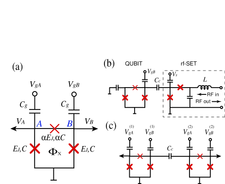
Figure 1a shows the qubit which consists of a superconducting loop containing three Josephson junctions mooij , threaded by an external flux close to half a flux quantum (). The Josephson energy and junction capacitance of two of the junctions are the same while those of the third junction are slightly smaller ( and , with ); such a combination is chosen only to simplify the calculations. In addition, two voltage sources and are capacitively connected to two of the islands ( and in Fig. 1a), while the third one is grounded 2JQ . The ungrounded islands are used to couple the qubit to the readout circuit (Fig. 1b) or to other qubits (Fig. 1c).
Let us first study the qubit, neglecting the effect of neighboring circuitry; if the coupling capacitance , the approximation is rather good. Having three Josephson junctions removes the necessity for finite inductance () to achieve bistability. Indeed, since the magnetic flux of the qubit is not used for readout, unlike in the three Josephson junction (3JJ) qubit mooij ; chiorescu ; ilichev , can be made extremely small. This significantly reduces the decoherence due to magnetic coupling to the environment (e.g. nuclear spins or magnetic impurities). Small makes the total flux through the loop almost equal to the external flux. The phase differences across the junctions are then constrained by the flux quantization condition: . Defining and , the Hamiltonian of the system is ()
where and are the momenta conjugate to and , is the potential energy, are the normalized gate charges, , , , and . At , has degenerate minima at , . The effect of the kinetic terms is to remove the degeneracy by making the tunneling between the two minima possible. TTunneling within a unit cell is described by the tunneling matrix element . In general, however, there is a probability of inter-cell tunneling with a tunneling matrix element . The effect of is to change the energy eigenstates and to bands with energy eigenvalues orlando ; greenberg
| (1) | |||||
| (2) | |||||
| (3) | |||||
is a conversion coefficient of greenberg , , , and is a dimensionless coefficient defined in Eq. (5)Delta .
At , the small flux and charge fluctuations () appear in second order:
| (4) | |||
| (5) |
Elimination of the first order terms, and therefore suppression of the dephasing due to them, suggests a perfect operation (magic) point for the qubit; high frequency fluctuations, however, may cause transition between the states. The second order charge and flux fluctuations influence the eigenenergies with coefficients (when ) and , respectively. To minimize their effect on coherence, one should make these coefficients small. Reducing one, however, will increase the other. An optimized point is only achievable in the charge-phase regime and depends on the relative importance of the charge and flux noises. In the design of 3JJ qubit mooij ; ilichev ; orlando , the parameters are chosen so as to get a vanishingly small (), but large (). While suppressing the effect of charge fluctuations, it leaves the qubit sensitive to flux fluctuations, even at the magic point. In our design, we aim to get a smaller , but larger . Indeed, is chosen to be small enough to suppress the effect of the second order charge fluctuations, but large enough to make the states of the qubit electrically distinguishable away from the magic point.
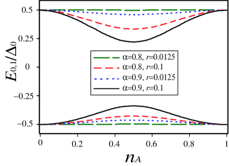
Figure 2 shows numerical results for and (obtained from diagonalization of the Hamiltonian) as a function of , at , , and for different values of and (, where is the charging energy). The agreement with Eqs. (1)–(3) is fairly good, although the exact symmetry between the upper and lower levels does not exist. At and , the eigenvalues show very small dependence on . At and/or at larger , on the other hand, they strongly depend on . This, as we shall see, is important for our readout and coupling schemes.
The numerical values of and are obtained by comparing the curves in Fig. 2 with Eqs. (1)–(3):
| (6) | |||||
| (7) |
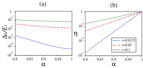
The dependence of and on is displayed in Fig. 3. decreases with , while exponentially increases, reaching 1 as . This is expected because at both barriers are equivalent, leading to equal tunnelling matrix elements (). It is also important to notice that the variations of both and with are significantly slower at larger . This is an important design aspect for large-scale systems (see below). Figure 4 shows dependence of and on . Again, their sensitivity to variations of (i.e. slope) is smaller at larger .
The island voltages are used to couple the qubit to its surroundings. in states is calculated taking the derivative of the corresponding eigenenergies with respect to : . At , we get
| (8) |
The expectation value of the excess charge on the island is then given by , where is the effective capacitance of the island. The voltage and charge of island can be determined by replacing .
When with integer , the voltages on both islands are zero. The qubit is therefore electrically decoupled from its neighbors. Away from this point, state-dependent voltages appear on the islands, coupling the qubit to its surrounding circuitry. For , the voltage on island is maximum when : . Directional coupling of the qubit to its neighbors is possible when
| (9) |
which lead to , while is close to its maximum. The reverse is obtained replacing .
The charge on the islands can be measured by a sensitive electrometer such as a single electron transistor (SET). Figure 1b illustrates a qubit coupled to an rf-SET rfSET as the readout device Lnote . rf-SET has already been used to read out charge qubits CQbit , and is known to be faster and more sensitive than ordinary SETrfSET . One of the gate voltages ( in the figure) is permanently grounded while the other () is used to switch the readout on and off. During quantum operations, and therefore there is no coupling to the readout circuit. At the time of readout, a gate voltage is (adiabatically) applied to generate a state-dependent voltage on the island. This voltage (or the island charge) is then detected by the rf-SET device to read out the qubit.
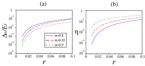
Figure 1c shows two qubits coupled via a capacitor , which connects the islands of the qubits. When both gate voltages are set to zero, the charge on the islands of each qubit will be independent of their states and therefore no coupling is expected. When both voltages become finite, state-dependent charges appear on the islands and the qubits will be coupled. For two identical qubits with and at , the coupling energy, to first order in , is
| (10) |
As expected, . Maximum coupling is achieved when . The remaining two islands ( and ) can be used for readout. In order to obtain qubit-qubit coupling without coupling to the readout circuits (and vice versa), the directional coupling scheme described in Eq. (9) (or reverse) should be employed.
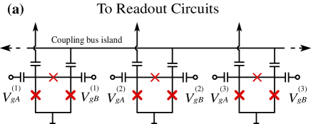
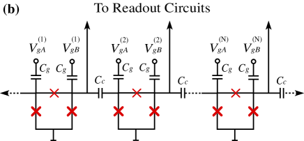
To make a quantum register, it is possible to couple several qubits via a common island. Figure 5a illustrates a configuration in which all qubits are capacitively coupled to a bus island (which should be small to ensure small capacitance). Each pair of qubits can be coupled by applying appropriate gate voltages to them, while other qubits remain decoupled from the island, as long as their island charges are kept at zero note . Coupling too many qubits to the bus island increases the island capacitance, reducing the coupling energy and affecting the quantum operation of all qubits. Depending on the characteristics of the qubits and the coupling capacitors, qubits can be coupled to each other using this scheme. A more scalable scheme is based on nearest neighbor coupling, as depicted in Fig. 5b. It is necessary to decouple the readout circuits from the qubits during two-qubit operations, e.g. by biasing away the rf-SETs. At the time of readout, the gate voltage of the qubit closest to the readout line will be moved away from zero, so that the island voltage of (only) that qubit affects the detector.
A typical set of parameters for the present design can be , and , which gives and . With the junction quality dictated by the rf-SET, we find GHz, leading to GHz and fF. Notice that gives a more than three orders of magnitude smaller than that of the 3JJ qubit of Ref. ilichev, (i.e. much smaller sensitivity to the flux fluctuations). As we mentioned before, choosing a large (compared to the 3JJ qubit) has also the benefit of reducing sensitivity to the system parameters. For example is more than ten times less sensitive to the variations of , , and , compared to the 3JJ qubit. This indeed is crucial for large-scale systems.
For charge fluctuations, we obtain , more than three orders of magnitude smaller than what one finds for charge qubits, but close to that of the quantronium qubit. Thus, the qubit has small sensitiveity to the charge fluctuations. Moreover, the separation between the first two states and the others is much larger than that in the quantronium qubit. With the suggested parameters, we find an anharmonicity coefficient (), more than 6 times the corresponding value () for Vion et al.’s qubit. This makes the qubit a well-defined two-level system and prevents leakage of quantum information to non-computational states. Such an anharmonicity is shown to be large enough to perform fast gate operations with the help of shaped pulses steffen .
Using the above parameters, we find the maximum island voltage to be V, more than two orders of magnitude smaller than that of a charge qubit. This significantly reduces electric coupling to the environment and/or to other qubits. Using a coupling capacitance fF, a charge of e appears on the SET’s island. With the reported rfSET ; CQbit charge sensitivity of e/, a measurement time of s is enough to read out the qubit. The measurement time is limited by the relaxation time of the qubit during the readout. A relaxation time of s mooij-new and a Rabi decay time of 2.5 s ilichev (which sets a lower limit) has been reported for the 3JJ qubit. Working in the charge-phase regime is expected to increase the relaxation time by reducing the sensitivity to magnetic field fluctuations. If the sensitivity of the rf-SET and the relaxation time of the qubit permit, one would like to have smaller to reduce backaction of the SET on the qubit.
For the coupling energy, the above parameters, with fF, give a maximum MHz. Stronger coupling requires larger and , at the expense of more sensitivity to charge fluctuations and the necessity for a more complicated treatment of the coupling Hamiltonian (beyond the first order perturbation). Magnetic coupling of the qubits is also possible if their self inductances are made large enough. A combination of both magnetic and capacitive coupling can be used to make robust quantum registers grigorenko . Such a possibility only exists in charge-phase regime. It should be emphasized that biasing away the qubits from the magic point during the coupling will increase the dephasing. Other methods of coupling at the degeneracy pointblais may therefore be advantageous.
In summary, we have proposed an implementation of a hybrid charge-phase qubit with three Josephson junctions. The voltages (charges) of the islands are used to read out and couple the qubits. Each qubit can be read out independently, without affecting the others in a quantum register. With the suggested set of parameters, the effect of the flux fluctuations is suppressed by more than three orders of magnitude compared to the 3JJ qubit, while the sensitivity to the system parameters is one order of magnitude smaller. The size of the loop can be made much smaller, significantly reducing the effect of coupling to magnetic environment. Compared to the charge-phase qubit of Vion et al. Vion , the proposed qubit can have less sensitivity to the charge fluctuations as well as better anharmonicity.
The author thanks M. Grajcar, J.P. Hilton, E. Il’ichev, A. Maassen van den Brink, A. Shnirman, A.Yu. Smirnov, and A.M. Zagoskin for stimulating discussions, B. Wilson for critically reading the manuscript, and G. Rose for suggesting multiple control gates.
References
- (1) Y. Nakamura, Yu.A. Pashkin, J.S. Tsai, Nature 398, 786 (1999);
- (2) A. Guillaume, J.F. Schneiderman, P. Delsing, H.M. Bozler, and P.M. Echternach1, Phys. Rev. B 69, 132504 (2004); T. Duty, D. Gunnarsson, K. Bladh, and P. Delsing, Phys. Rev. B 69, 140503 (2004).
- (3) J.E. Mooij, T.P. Orlando, L. Levitov, L. Tian, C.H. van der Wal, and S. Lloyd,, Science 285, 1036 (1999).
- (4) I. Chiorescu, Y. Nakamura, C.J.P.M. Harmans, and J.E. Mooij, Science 299, 1869 (2003).
- (5) E. Il’ichev, N. Oukhanski, A. Izmalkov, Th. Wagner, M. Grajcar, H.-G. Meyer, A.Yu. Smirnov, Alec Maassen van den Brink, M.H.S. Amin, A.M. Zagoskin, Phys. Rev. Lett. 91, 097906 (2003).
- (6) R.C. Ramos, M.A. Gubrud, A.J. Berkley, J.R. Anderson, C.J. Lobb, and F.C. Wellstood, IEEE Trans. Appl. Supercond. 11, 998 (2001); Y. Yu, S. Han, X. Chu, S.-I. Chu, Z. Wang, Science 296, 889 (2002); J.M. Martinis et al., S. NAm, J. Aumentado, C. Urbina, Phys. Rev. Lett. 89, 117901 (2002); A.J. Berkley, H. Xu, R.C. Ramos, M.A. Gubrud, F.W. Strauch, P.R. Johnson, J.R. Anderson, A.J. Dragt, C.J. Lobb, and F.C. Wellstood, Science 300, 1548 (2003).
- (7) D. Vion, A. Aassime, A. Cottet, P. Joyez, H. Pothier, C. Urbina, D. Esteve, and M.H. Devoret, Science 296, 886 (2002).
- (8) Similar structures with two Josephson junctions have been proposed by A.B. Zorin, Physica C 368, 284 (2002); J.R. Friedman and D.V. Averin, Phys. Rev. Lett. 88, 050403 (2002); D.A. Ivanov, L.B. Ioffe, V.B. Geshkenbein, and G. Blatter, Phys. Rev. B 65, 024509 (2002).
- (9) T.P. Orlando, J.E. Mooij, L. Tian, C.H. van der Wal, L.S. Levitov, S. Lloyd, and J.J. Mazo, Phys. Rev. B 60, 15398 (1999).
- (10) Ya.S. Greenberg, A. Izmalkov, M. Grajcar, E. Il’ichev, W. Krech, H.-G. Meyer, M.H.S. Amin, and A. Maassen van den Brink, Phys. Rev. B 66, 214525 (2002).
- (11) Equation (3) is valid only approximately when is large.
- (12) R.J. Schoelkopf, P. Wahlgren, A.A. Kozhevnikov, P. Delsing, and D.E. Prober, Science 280, 1238 (1998); M.H. Devoret, and R.J. Schoelkopf, Nature 406, 1039 (2000).
- (13) One should make sure that the rf-SET’s inductor ( in Fig. 1b) does not interfere with qubit’s operation.
- (14) Applying a gate voltage to one qubit, or to the rf-SET ( in Fig. 1b), also affects other qubits. Appropriate gate voltages should be applied to compensate for this.
- (15) M. Steffen, J.M. Martinis, and I. Chuang, Phys. Rev. B 68, 224518 (2003); M.H.S. Amin, preprint (cond-mat/0407080).
- (16) A. Lupascu, C.J.M. Verwijs, R.N. Schouten, C.J.P.M. Harmans, J.E. Mooij, preprint (cond-mat/0311510).
- (17) I.A. Grigorenko and D.V. Khveshchenko, preprint (cond-mat/0312349).
- (18) see e.g. A. Blais, A. Maassen van den Brink, A.M. Zagoskin, Phys. Rev. Lett. 90, 127901 (2003).