Enhanced millimeter wave transmission through subwavelength hole arrays
Abstract
In this letter, we explore, both experimentally and theoretically, the existence in the millimeter wave range of the phenomenon of extraordinary light transmission though arrays of subwavelength holes. We have measured the transmission spectra of several samples made on aluminum wafers by using an AB MillimetreTM Quasioptical Vector Network Analyzer in the wavelength range between mm to mm. Clear signals of the existence of resonant light transmission at wavelengths close to the period of the array appear in the spectra.
The discovery of the phenomenon of extraordinary optical transmission (EOT) observed in two-dimensional (2D) arrays of subwavelength holes perforated in optically thick metallic films Ebbesen , has opened up the possibility of using subwavelength apertures for a variety of optoelectronic applications. A previous theoretical workLMM on Ebbesen’s experiment assigned the EOT phenomenon to the excitation of surface electromagnetic (EM) modes occurring on corrugated metal surfaces. Furthermore, these modes (and EOT) were found to appear even in a simpler model where the metal was treated as a perfect conductor LMM ; Pendry04 . These surface leaky modes are similar to the ones appearing in perfectly conducting sinusoidal gratings Maystre . As the perfect conductor approximation should be even more valid for larger wavelengths, the previously cited work LMM pointed out to the possibility of the existence of EOT in other ranges of the EM spectrum. Moreover, very recently, there have been some experimental studies of EOT in the THz regime in doped semiconductors Rivas and in metals theothers that seem to suggest that EOT is also present in this frequency regime.
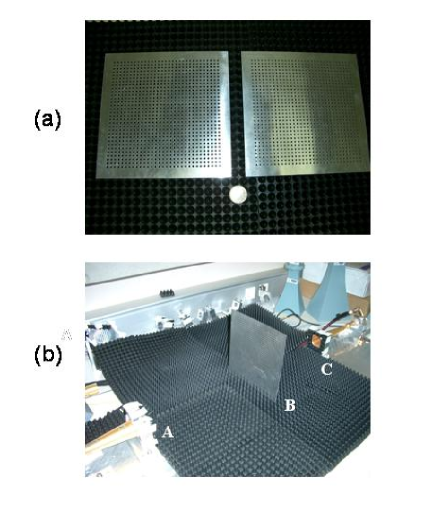
Here we move a step further by studying, both experimentally and theoretically, the transmission of EM radiation through 2D arrays of subwavelength holes in the millimetric wave range. In order to carry out our analysis, several prototypes have been fabricated in aluminum wafers of different thicknesses (), ranging from mm to mm. All square arrays () have a lattice constant () of mm and two different hole radius () are considered: and mm (see Fig.1a).
It is important to note here that, before Ebbesen experiment, there were experimental studies of transmission of light through arrays of holes in the far infrared Ulrich , mid infrared Rhoads and infrared Keilmann ranges. However, these previous experiments were performed for hole sizes and lattice constants () such that was smaller than the cut-off wavelength (). EOT appears essentially , but when the modes inside the hole are evanescent, i.e., when .
Let us first discuss the theoretical predictions for the transmittance spectra given by the framework described inLMM for the study of EOT in the optical range. Within this formalism, we consider a metal film perforated by an infinite 2D square array of holes. As aluminum behaves as a quasi-perfect conductor in the millimeter wave regime, we have simplified our formalism by considering perfect metal boundary conditions (PMBC) at all interfaces forming the structure. Within the PMBC approximation, this theoretical framework is rigorous, being equivalent to the one developed some time ago for studying inductive grids McPhedran .
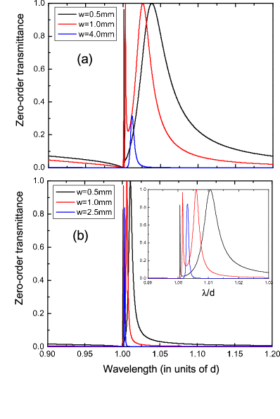
In Fig. 2 we show our numerical simulations for the zero-order transmittance spectra of infinite arrays of holes corresponding to the six samples fabricated. In all calculations we show in this paper we assume that a normal incident plane wave is impinging at the perforated metal film. Panel (a) displays the cases with mm () and three different thicknesses and in panel (b) the corresponding three transmittance spectra with mm () are shown. In the region , calculations rendered in panels 2a and 2b predict the appearance of EOT resonances. For each of the thinner samples considered (mm and mm), the two surface EM resonances excited at the two surfaces of the metallic film are coupled, leading to two transmission peaks that reach LMM . However, for the thicker samples analyzed (mm for mm and mm for mm), this EM coupling is negligible and only one transmission peak appears in the spectra.
Transmission through our samples is measured by using an AB MillimeterTM Quasioptical Vector Network Analyzer in the frequency range between to GHz. In Fig.1b we show a photograph of the experimental set-up. A vertically polarized pure gaussian beam is generated by a corrugated horn antenna (A). This beam propagates up to the sample (B) that is located at cm to the antenna. The diameter of the beam waist at the sample location is around cm at the wavelength range of interest. In this way, the illumination of the hole arrays is rather uniform. The transmitted beam is finally collected into a horn antenna (C) that is placed at cm from the sample. The samples are embedded into a sheet of millimeter wave absorbing material (not shown in Fig.1b for illustrative purposes) in such a way that any possible diffracted beam generated by the edges of the samples is absorbed by the sheet and not collected by the receiver antenna (C).
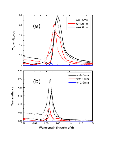
Fig.3 shows experimental transmission spectra obtained for the six different samples analyzed. We represent the collected transmission power, (normalized to the collected power when no sample is present) as a function of wavelength, when the holes have radius mm (top panel, full lines) and when mm (bottom panel, full lines). In the case of mm and mm (black curve in panel a), the transmission at resonance (located at slightly larger than ) can be as large as although the holes only occupy of the unit cell. For mm and mm (red full curve), the transmission resonance also appears, reaching at maximum. This kind of transmission resonances is also present in the thinner samples (mm and mm, see panel b) of the arrays of holes with smaller radius (mm) but the transmittance peaks associated are much lower than the ones obtained for mm. For the thicker films analyzed (mm for mm and mm for mm), the collected power is extremely small and no fingerprints of transmission resonances are observed. As the measured transmission resonances appear in a frequency range in which the holes only support EM evanescent waves, we can safely conclude that EOT also takes place in the millimeter wave range, as theory predicted.
However, there is a strong disagreement between theory and experiment as regards the absolute value of the transmission peaks. A possible reason for this disagreement could be originated by the intrinsic finite size of our arrays (). In order to explore in more detail this possibility, we have applied a theoretical formalism recently developed in our group that is able to analyze the optical properties of finite collections of holes drilled in a metallic film Jorge . In this method, first we assume an artificial square supercell of side in which the array of holes is contained (). Then, we apply a modal expansion of the EM fields (plane waves in vacuum regions and TE/TM modes inside the holes evanes ) and we match these fields considering PMBC. At the end of this procedure, a set of linear equations for the expansion coefficients of the EM-fields at the different holes of our structure is established. As the considered supercell is fictitious, we have to take the limit in the different terms appearing in this set of linear equations. Once the expansion coefficients are obtained, the total transmittance through the 2D subwavelength hole array can be finally calculated.
In both panels of Fig. 3 (dashed curves), we show the total transmittance spectra for the six arrays of holes as obtained with our new theoretical tool. If we compare the theoretical results for the 31x31 arrays (dashed lines in Fig.3) with the corresponding ones for infinite arrays (Fig.2) there are two main changes. Firstly, the very narrow transmission peaks appearing at for the infinite arrays are not present in the spectra of finite arrays. Secondly, there is a strong reduction of the transmission peaks when going from infinite arrays to finite ones; this reduction is more dramatic for the structures with mm than for the arrays with mm. These two changes lead to a much better agreement between theoretical predictions and experimental results (see Fig.3). This good agreement allows us to state that the strength of transmission resonances associated to the EOT phenomenon observed in subwavelength hole arrays is basically controlled by the size of the arrays.
In conclusion, we have demonstrated that the phenomenon of extraordinary EM transmission through arrays of subwavelength holes is also present in the millimeter wave range. Moreover, we have also shown that one of the key parameters to observe this phenomenon is the number of periods of the array.
Financial support by the Spanish MCyT under grant BES-2003-0374 and contracts MAT2002-01534 and MAT2002-00139 and by EC project FP6-NMP4-CT-2003-505699 (“Surface Plasmon Photonics”) is gratefully acknowledged.
References
- (1) T. W. Ebbesen, H.J. Lezec, H. Ghaemi, T. Thio, and P.A. Wolff, Nature (London) 391, 667 (1998).
- (2) L. Martín-Moreno, F.J. García-Vidal, H.J. Lezec, K.M. Pellerin, T. Thio, J.B. Pendry, and T.W. Ebbesen, Phys. Rev. Lett. 86,1114 (2001).
- (3) J.B. Pendry, L. Martín-Moreno, and F.J. García-Vidal, Science Express, 10.1126, 8 July 2004.
- (4) D. Maystre, General study of grating anomalies from surface waves, in Electromagnetic Surface Modes, Ed. A.D. Boardman (John Wiley and Sons, 1982).
- (5) J. Rivas, C. Schotsch, P. Haring Bolivar and H. Kurz, Phys. Rev. B, 201306(R) (2003).
- (6) D. Qu, D. Grischkowsky, and W. Zhang, Opt. Lett. 29, 896 (2004); Y.-H. Ye and J.Y. Zhang, Appl. Phys. Lett.84, 2977 (2004); H. Cao and A. Nahata, Opt. Express 12, 1004 (2004).
- (7) R. Ulrich, Infrared Physics 7, 37 (1967).
- (8) C.M. Rhoads, E.K. Damon, and B.A. Munk, Appl. Opt. 21, 2814 (1982).
- (9) F. Keilmann, Int. Journal of Infrared and Millimeter Waves 2, 259 (1981).
- (10) R.C. McPhedran and D. Maystre, Appl. Phys. 14, 1 (1977).
- (11) J. Bravo-Abad, F.J. Garcia-Vidal, and L. Martin-Moreno (to be published).
- (12) As we are working in the subwavelength regime, considering just the two least decaying modes in each hole is enough to obtain accurate numerical results.