Observation of “Partial Coherence” in an Aharonov-Bohm Interferometer with a Quantum Dot
Abstract
We report experiments on the interference through spin states of electrons in a quantum dot (QD) embedded in an Aharonov-Bohm (AB) interferometer. We have picked up a spin-pair state, for which the environmental conditions are ideally similar. The AB amplitude is traced in a range of gate voltage that covers the pair. The behavior of the asymmetry in the amplitude around the two Coulomb peaks agrees with the theoretical prediction that the spin-flip process in a QD is related to the quantum dephasing of electrons. These results constitute evidence of “partial coherence” due to an entanglement of spins in the QD and in the interferometer.
pacs:
73.21.La, 73.23.Hk, 03.65.YzMesoscopic systems are excellent test stages of quantum coherence and decoherence, which has been one of the most significant and challenging issues both for fundamental physics and for the realization of quantum devices imry . In the context of the “system-plus-environment” model, decoherence of a particular state of the system occurs through its coupling to infinite degrees of freedom of the environment leggett . The environment affects the interference in two ways: by dissipation of the system’s kinetic energy into the environment and by phase randomization via interaction with environmental degrees of freedom.
Aharonov-Bohm (AB) interference is a standard mesoscopic tool for probing the degree of coherence AB1963 ; most simply, its amplitude is a good measure of coherence. In our previous paper Kobayashi2002JPSJ , we reported that the AB amplitude in a semiconductor sample is markedly affected by the coupling to the environment Seelig . In a hybrid system of an AB ring and a quantum dot (QD) Yacoby1995PRL ; Katsumoto1996JPSJ ; Schuster1997Nature ; Buks1998Nature ; vdWiel2000Science ; Ji ; Kobayashi2002PRL ; Kobayashi2003PRB , one would be able to vary the strength of such coupling. Buks et al. Buks1998Nature used a dot in an AB ring as a which-path detector. In their setup, the diminishment of the AB amplitude was not very large, but correlation with shot noise in the current flowing through a quantum point contact (QPC) placed next to the dot was detected. Because it is unlikely that decoherence occurs when the current meter “notices” the passage of an electron over the dot from the shot noise, this result gives rise to an essential question: at which moment does the decoherence occur?
In the above experiment, the strength of quantum entanglement between the object state (electron in the AB ring) and the detector state (electrons passing the QPC) is unknown due to the spatial separation. Hence it is desirable to examine a system with strong entanglement between an object and a detector. In this Letter, we report experiments on quantum dephasing, , phase randomization due to a strong entanglement among spins in a QD and those of conducting electrons.
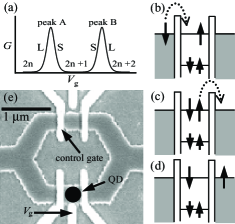
For a system consisting of an AB ring and a QD, the possibility of quantum decoherence due to strong object-detector coupling has been pointed out theoretically Akera ; Konig . The scenario is as follows. Consider a QD where the single-electron energy levels with Kramers degeneracy are distributed with nearly equal spacing according to the random matrix theory (RMT) mehta . Due to the single-electron charging energy , electronic states of the QD can be labeled with the electron number . Here we trace the process where the ground state shifts as with the increase in the gate voltage () of the QD. There are two Coulomb peaks A and B in this process corresponding to the two transitions, as schematically depicted in Fig. 1(a).
On the left side of peak B, an electron passes the dot with the cycle . In the initial state, the topmost orbital is half-occupied with an electron of, for example, up-spin, as shown in Fig. 1(b). From the intermediate state (Fig. 1(c)), an electron with either up- or down-spin can escape to the electrode. If we label the spin states in the dot by (or ) and those of the conducting electron by (or ), the state with an outgoing electron is written as (Fig. 1(d)). In this entangled state, the spin-flip part is directly related to dephasing because it leaves a trace on the QD Konig .
On the right side of peak B, the process changes to where no spin-flip is allowed due to the Pauli principle. Hence the total quantum coherence is expected to be retained more on the right side than on the left side of peak B. The tendency on the left and right sides of a Coulomb peak is reversed when passes through peak A. As a result, the AB amplitude changes as labeled by “S” (small) and “L” (large) in Fig. 1(a). An experimental observation of such asymmetry GefenCM2002 , therefore, provides proof of “partial coherence” Konig of the dot-ring spin-entangled state.
We fabricated a QD-AB-ring system from a GaAs/AlGaAs two-dimensional electron gas wafer (mobility and sheet carrier density ) by electron-beam lithography, wet etching and vacuum deposition of metallic gates (Fig. 1(e)). A QD was formed in the lower arm of the AB ring by negatively biasing two outer gates. The middle gate () was used to control the electrostatic potential of the QD. One of the three gates on the upper arm was used to control the transmission of the reference arm. The sample was cooled in a dilution refrigerator with a base temperature of 30 mK. The conductance was measured by the standard lock-in technique in a two-terminal setup.
The scenario for detecting partial coherence associated with the spin-flip process described above is highly idealized in that all aspects of the system and environment, other than the occupation of the topmost level, are assumed to be identical throughout the region of Coulomb peaks A and B. In the actual experiment, it is crucial to assess to what degree this condition is fulfilled. Indeed, there are many factors that might affect the AB amplitude as a function of , such as a change in the electrostatic potential. Furthermore, the simplest approximation of RMT rarely holds for semiconductor QDs Patel1998PRL , and electron correlation can give rise to high-spin states. Therefore, the simple picture that single-electron orbital levels are sequentially occupied by spin-up and -down electrons is far from reality.
Nevertheless, one can hope to find an energy window (, a gate voltage) where the simplest “spin-pair” model is a good approximation: Only a single Kramers degenerate state should exist just above a closed-shell many-electron state in the energy diagram. Although such a spin-pair state rarely exists in semiconductor QDs Patel1998PRL ; Luscher2001PRL ; Lindemann2002PRB , once it is found, we can circumvent the above problems and attribute the difference in the coherence to the spin entanglement, because the conditions other than the spin state are ideally equal on both sides of Coulomb peaks in this window.
A spin-pair state appears as twin neighboring Coulomb peaks (spin-pair peaks). The conditions required for such twin peaks are as follows. I) They should be identical in their magnetic field dependences of their positions and heights. II) The above dependence should be different from those of neighboring ones because the conductions at neighboring peaks are through different single-electron orbital states. III) The addition energy between the peaks is likely to be smaller than those of neighboring ones because there should be no contribution of orbital energy. Note that condition II excludes high-spin states.
With these criteria, we set out to find such twin Coulomb peaks. Coulomb peaks are highly sensitive to environmental charge fluctuation and a transition of a single-impurity around the sample changes their positions. On the other hand, the present experiment requires complete stability throughout the measurement. Periods for a single set of measurements are thus limited and we can only find a single pair which fulfills the above conditions, as described below. The positions () and heights () of nine successive Coulomb peaks, which are obtained by fitting the standard formula of the orthodox theory Averin , are shown in Figs. 2 (a) and (b), respectively, as a function of magnetic field . The conductance of the reference arm is reduced to make the AB amplitude small ( 10 % of ), so the distribution of the amplitude from peak to peak is negligible when we calculate the correlation of the peak height.
As seen in Fig. 2(a), the line shapes of magnetic field dependences of peak positions are similar. This is natural in light of the recent understanding of the nature of a wave function in disordered quantum dots Nakanishi . The essence of the theory is as follows. If we set the starting point at a dot with no randomness, every orbital state has well-defined spatial symmetry. The randomness of the confinement potential introduces “children” states, which are similar in spatial distribution to the parent state. They are different, however, particularly at the edge of the envelope, and hence the difference should be emphasized by taking a close look at the traces of position. On the other hand, the conductance through the dot is dominated by the edge of the wave function, and the Coulomb peak height is more sensitive to the difference. Actually, the difference is clear in the peak heights shown in Fig. 2(b).
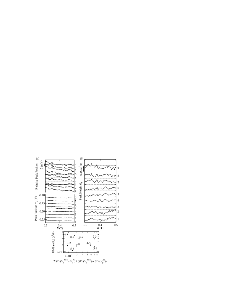
For a more quantitative comparison, we show in Fig. 2(c) the RMS’s of the difference in peak height () and the standard deviations (SDs) of the peak spacing () divided by the average value of each peak position SD for the neighboring peak combinations in Fig. 2(a). The pair 5-6 fulfills conditions I and III, i.e., the point 5-6 is close to the lower left corner and 4-5 and 6-7 are far from it. This pair also satisfies condition II, as shown in Fig. 2(a) comment . From this observations we conclude that the pair 5-6 is a spin pair which we have sought.
We then proceed to the next step of examining the AB amplitude around the spin-pair peaks 5 and 6. Figure 3(a) is a gray-scale plot of the AB component in the total conductance as a function of and extracted by fast Fourier transform. We have chosen the range on the basis of the stability of the peak position in order to eliminate artifacts of level crossing, and the peak positions are indicated by vertical dashed lines. As seen in Fig. 3(a), the phase of the AB oscillation changes by at each Coulomb peak. In some regions of the magnetic field, the change is very steep and shows the feature of phase locking, reflecting the two-terminal setup Yeyati1995PRB ; Yacoby1996PRB .
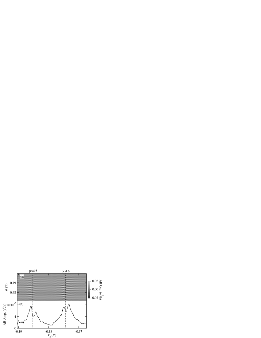
In Fig. 3(b), we plot the AB amplitude averaged over ten periods around T as a function of . The large dips in the AB amplitude at the peak position are due to phase locking and separate the AB amplitudes to the left and right of the peaks, which is an advantage of the two-terminal setup. The two amplitude peaks at both sides of each dip have different heights. For Coulomb peak 5, the left peak is larger than the right, while the right peak is larger than the left one for Coulomb peak 6. This observation is exactly what we expected from Fig. 1(a). Note that possible distortion due to the Fano effect is averaged out in the above analysis because the Fano parameter oscillates sinusoidally with the period of AB oscillation Kobayashi2002PRL ; Kobayashi2003PRB ; Konig . We believe that all the possible artifacts are eliminated in the above analysis, and our observation constitutes evidence for partial coherence due to spin-flip scattering in a QD. As for other non-spin-pair peaks, we sometimes observed asymmetry, although their direction seemed to change randomly. We presume that the same spin physics also plays a critical role in them, but cannot be conclusive because the detailed information on the spin and orbital states at those peaks is not known.
The shapes of the averaged amplitude in Fig. 3(b) for the two Coulomb peaks are slightly different, while ideally, they would be mirror images of each other with respect to the center of the Coulomb valley. This is probably due to a remote effect of the gate electrode to some part (e.g., the reference arm) of the device other than the quantum dot. Such a remote effect is linear in the gate voltage (otherwise the total conductance should be largely affected by the gate voltage) and only causes a distortion from peak to peak, thus, the spin-pair approximation for the QD still holds.
For the spin-flip process, it is also presumed that the asymmetry should be removed by applying a high magnetic field which lifts the Kramers degeneracy Akera ; Konig . Unfortunately, in the present experiment, such a high field was not attainable. However we have performed the same procedure for about 50 Coulomb peaks of three different samples at low ( 0.5 T) and high ( 2 T) fields; the Zeeman energy of the latter is about 50 eV for GaAs, and is comparable to the spacing of the single-particle level in the QD (typically under the present conditions). Although no clear spin-pair state is found, at low fields, 80 % of the peaks exhibit the asymmetry of coherence, while 60 % of them are almost symmetric at high fields. This suggests that the spin-flip process plays an important role in the coherence through non-spin-pair states, although, unfortunately, none of the measured peaks showed the spin-pair features as clear as those of peaks 5-6.
We would like to comment on the question of whether spin flip or spin entanglement is truly a dephasing process. The diminishment of the AB amplitude due to spin rotation is a coherent process and full rotation to recovers the original amplitude, as demonstrated by neutron interference experiments Werner1975PRL ; Rauch1975PL . However, in the system-plus-environment model, the spin rotation at a QD causes diminishment of the coherence factor Stern1990PRA ; Zurek2003RMT , if we classify the QD as part of the environment. As mentioned in Ref. Konig , when the Kondo state is fully developed, the classification of the QD as part of the environment is invalid and the dephasing due to the above spin scattering thus disappears at .
In conclusion, we have observed the asymmetry of the AB interference signal through a QD in an energy window for which the spin-pair state is a good approximation. The present results are in good agreement with the theoretical predictions on quantum dephasing due to spin-flip scattering and provide evidence of the partial coherence of electrons which pass a QD with a localized moment.
We thank K. Ensslin, Y. Gefen, J. König, and T. Nakanishi for helpful discussion. This work is supported by a Grant-in-Aid for Scientific Research and by a Grant-in-Aid for COE Research (“Quantum Dot and Its Application”) from the Ministry of Education, Culture, Sports, Science, and Technology of Japan. K.K. is supported by a Grant-in-Aid for Young Scientists (B) (No. 14740186) from Japan Society for the Promotion of Science.
References
- (1) e.g., Y. Imry, Introduction to Mesoscopic Physics, Ch. 3 (Oxford, 1997).
- (2) e.g., A. J. Leggett, Quantum Tunnelling in Condensed Media, Ch. 1 (eds. Y. Kagan and A. J. Leggett, Elsevier, 1992).
- (3) Y. Aharonov and D. Bohm, Phys. Rev. 115, 485 (1963).
- (4) K. Kobayashi, H. Aikawa, S. Katsumoto, and Y. Iye, J. Phys. Soc. Jpn. 71, 2094 (2002).
- (5) G. Seelig and M. Büttiker, Phys. Rev. B 64, 245313 (2001); G. Seelig and M. Büttiker, cond-mat/0304022.
- (6) A. Yacoby, M. Heiblum, D. Mahalu, and H. Shtrikman, Phys. Rev. Lett. 74, 4047 (1995).
- (7) S. Katsumoto and A. Endo, J. Phys. Soc. Jpn. 65, 4086 (1996).
- (8) R. Schuster, E. Buks, M. Heiblum, D. Mahalu, V. Umansky, and H. Shtrikman, Nature 385, 417 (1997).
- (9) E. Buks et al., Nature 391, 871 (1998).
- (10) W. G. van der Wiel et al., Science 289, 2105 (2000).
- (11) Y. Ji, M. Heiblum, D. Sprinzak, D. Mahalu, and H. Shtrikman, Science 290, 779 (2000); Y. Ji, M. Heiblum, and H. Shtrikman, Phys. Rev. Lett. 88, 076601 (2002).
- (12) K. Kobayashi, H. Aikawa, S. Katsumoto, and Y. Iye, Phys. Rev. Lett. 88, 256806 (2002).
- (13) K. Kobayashi, H. Aikawa, S. Katsumoto, and Y. Iye, Phys. Rev. B 68, 235304 (2003).
- (14) H. Akera, Phys. Rev. B 47, 6835 (1993); H. Akera, Phys. Rev. B 59, 9802 (1999).
- (15) J. König and Y. Gefen, Phys. Rev. Lett. 86, 3855 (2001); J. König and Y. Gefen, Phys. Rev. B 65, 045316 (2002).
- (16) M. L. Mehta, “Random Matrices and Statistical Theory of Energy Levels”, (Academic Press, 1967).
- (17) Y. Gefen, cond-mat/0207440.
- (18) S. R. Patel et al., Phys. Rev. Lett. 80, 4522 (1998).
- (19) S. Lüscher, T. Heinzel, K. Ensslin, W. Wegscheider, and M. Bichler, Phys. Rev. Lett. 86, 2118 (2001).
- (20) S. Lindemann, T. Ihn, T. Heinzel, W. Zwerger, K. Ensslin, K. Maranowski, and A. C. Gossard, Phys. Rev. B 66, 195314 (2002).
- (21) D. V. Averin and K. K. Likharev, in Mesoscopic Phenomena in Solids, ed. B. L. Altshuler, P. A. Lee, and R. A. Webb, (North-Holland, New York, 1991).
- (22) T. Nakanishi, K. Terakura, and T. Ando (submitted to Phys. Rev. B).
- (23) We cannot exclude the possibility that the pair 1-2 is also a spin-pair. Unfortunately the stability of the dot was not enough to perform the measurement on this pair.
- (24) A. L. Yeyati and M. Buttiker, Phys. Rev. B 52, R14360 (1995).
- (25) A. Yacoby, R. Schuster, and M. Heiblum, Phys. Rev. B 53, 9583 (1996).
- (26) S. A. Werner, R. Colella, A. W. Overhauser, and C. F. Eagen, Phys. Rev. Lett. 35, 1053 (1975).
- (27) H. Rauch, A. Zeilinger, G. Badurek, A. Wilfing, W. Bauspiess, and U. Bonse, Phys. Lett. 54A, 425 (1975).
- (28) A. Stern, Y. Aharonov, and Y. Imry, Phys. Rev. A 41, 3436 (1990).
- (29) W. H. Zurek, Rev. Mod. Phys. 75, 715 (2003).