Multi- configurations
Abstract
Using resonant x-ray scattering to perform diffraction experiments at the U M4 edge novel reflections of the generic form have been observed in UAs0.8Se0.2 where , with reciprocal lattice units, is the wave vector of the primary (magnetic) order parameter. The reflections, with of the magnetic intensities, cannot be explained on the basis of the primary order parameter within standard scattering theory. A full experimental characterisation of these reflections is presented including their energy, azimuthal and temperature dependencies. On this basis we establish that the reflections most likely arise from the electric dipole operator involving transitions between the core and partially filled states. The temperature dependence couples the peak to the triple- region of the phase diagram: Below K, where previous studies have suggested a transition to a double- state, the intensity of the is dramatically reduced. Whilst we are unable to give a definite explanation of how these novel reflections appear, this paper concludes with a discussion of possible ideas for these reflections in terms of the coherent superposition of the 3 primary (magnetic) order parameters.
pacs:
75.25.+z,75.10.-bI INTRODUCTION
Since their discovery in 1963 by Kouvel and Kasper Kouvel and Kasper (1963), multi– configurations have generated their share of confusion in the description of magnetic structures. The ambiguities arise since magnetic systems commonly lower their free energy by formation of domains. This eventuality frequently renders the best-known technique for their microscopic identification, neutron diffraction, impotent in the determination as to whether the magnetic structure is single- or multi-. The respective characteristics are that a single- configuration has only one magnetic propagation vector in any given magnetic domain whilst a multi- configuration is defined by the simultaneous presence of more than one such propagation vector. Given the possibility of multiple scattering, one immediately sees the likelihood of confusion in the interpretation of diffraction peak intensities from a multi-domain sample.
Neutron diffraction is a bulk technique, sensitive to the spatial periodicities of the magnetic field modulation. In general one cannot locate the scattering volume from which the diffraction peaks arise to a precision better than that given by the incident and scattered beams’ intersection with the sample. Given incident flux limitations, even at the most powerful neutron sources, beams can rarely be made sufficiently small (on the scale of magnetic domains) to identify unambiguously the magnetic configuration from intensity measurements in a multi-domain sample. External perturbations can, of course, change the domain populations and may allow identification, but this always begs the question as to whether the external perturbation may have changed the intrinsic magnetic configuration.
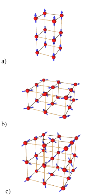
To be specific we take the case of the system UAs1-xSex where complete solid solutions exist and a considerable amount of neutron diffraction has been performed Kuznietz et al. (1987). Diagrams of the possible magnetic structures for are shown in Figure 1. The single- configuration has 3 distinct (tetragonal) domains, as does the state, whilst the cubic phase forms in a single domain. In these illustrations the repeat distance of the magnetic structure is twice the NaCl-type chemical unit cell, so the magnitude of the wave vector of the magnetic modulation is given by reciprocal lattice units (rlu). The primary magnetic reflections are then of the form where the indicates a permutation over indexes. These reflections, which are the only ones observed by neutron diffraction, are also imaged by resonant x-ray scattering (RXS), via the electric dipole (E1) scattering amplitude Longfield et al. (2001). In addition, the RXS cross section exhibits F(2) dipole amplitudes Hannon et al. (1988); Hill and McMorrow (1996) which give rise to peaks at positions of the form . The symmetries of the F(1) and F(2) terms may be exploited to distinguish respectively between single- and or structuresLongfield et al. (2002).
Under the constraints of the geometric structure factor, the amplitude projects, on a given scattering centre, a pair of the order parameters which, given inter-site phase coherence yields Bragg diffraction peaks of the form . The respective , assignments have been experimentally verified through the polarisation and azimuthal dependence of the scattered photons Longfield et al. (2002). Moreover, even though both amplitudes are electric dipole in origin, the contributions from the uranium scattering amplitudes have different matrix elements and are distinguished by their resonant energy and lineshape from the profiles Longfield et al. (2002); Paixão et al. (2002); Lovesey et al. (2003).
In the course of these experiments an additional group of reflections, much weaker than the other two sets described above, of the generic form have been observed. In this paper we give details characterising these reflections and our difficulty in explaining them within conventional scattering theory.
II EXPERIMENTAL DETAILS AND RESULTS
Experiments were performed with incident polarisation of the photon beam at the ID20 beamlineID (2), ESRF, Grenoble, France in the configuration used in previous workLongfield et al. (2002). The studies were carried out on a single crystal of UAs0.8Se0.2 which, above a tetragonal distortion at K, exhibits the cubic rock salt structureLongfield et al. (2001). On warming, UAs0.8Se0.2 is known to pass from a magnetic configuration of commensurate () to incommensurate ( wave vector at K, and to the paramagnetic state at K Kuznietz et al. (1987); Longfield et al. (2001). It has been shown, using a combination of both neutron and x-ray techniques Kuznietz et al. (1987); Longfield et al. (2002), to adopt a multi- structure for K.
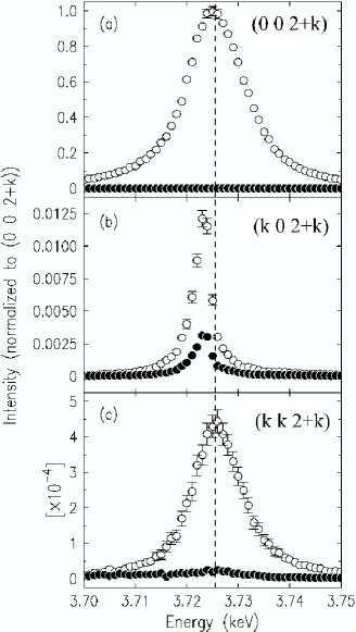
Representative reflections for the , and peaks are illustrated in Figure 2, where the dependence on incident photon energy of the scattered intensity at the positions (0 0 5/2), (1/2 0 5/2) and (1/2 1/2 5/2), for both the and channels of the cross section at T = 70 K are shown. In all cases these energy scans are characterised by sharp wave vector profiles indicative of long-range order. As Figure 2 shows, the (1/2 1/2 5/2) peak appears only in the channel with a resonant energy and width comparable to that of the (0 0 5/2), evidence which already suggests that the peak may arise from the dipole (E1) amplitude.
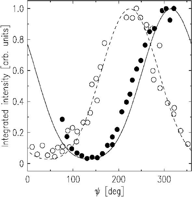
Figure 3 shows the azimuthal dependence of the intensity of the reflections (1/2 1/2 5/2) and (–1/2 1/2 5/2) in the channel. The smooth variation of the intensity eliminates multiple scattering as a possible source of these peaks. The lines are calculated from the term of the E1 cross section, assuming a symmetry breaking vector along , parallel to {i.e. along [1 1 1] for the (1/2 1/2 5/2) and along [-1 1 1] for the (-1/2 1/2 5/2)}. The agreement between the data and this model with only one overall scale factor is excellent. These aspects are discussed further below.
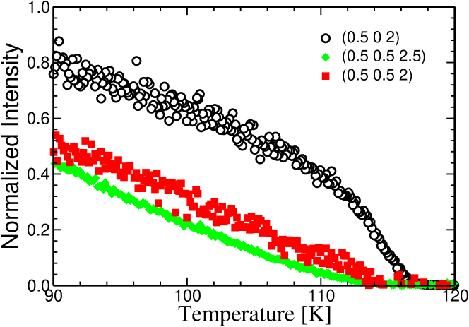
The temperature dependencies of the (0 0 5/2), (1/2 0 5/2) and (1/2 1/2 5/2) peaks are given in the Figure 4. The (0 0 5/2) reflection represents one primary order parameter whilst the (1/2 0 5/2) reflection involves two simultaneously present at each scattering centre and propagating with fixed phase relationship. The temperature dependencies of , and for 70 K 117 K in Figure 2 lie approximately in the ratio .
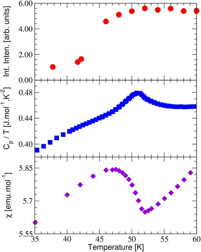
Detailed specific heat and magnetisation measurements were made on the sample used in the diffraction experiments at the User Facility, Institute for Transuranium Elements, Karlsruhe ITU . We show in Figure 5 the results of (a) the integrated intensity of the (1/2 1/2 5/2) peak, (b) heat capacity at zero field, and (c) the susceptibility in a magnetic field of 0.1 T, as a function of temperature. The loss of intensity observed in the reflection is coupled to the nominal transitions seen in both specific heat and susceptibility at (Ref. Longfield et al., 2001).
III DISCUSSION
Before turning to a possible explanation of this effect, we recapitulate the phase diagram of the UAs0.8Se0.2 as suggested by earlier neutron Kuznietz et al. (1987) and RXS experiments Longfield et al. (2001). First, the disappearing intensity of the peak and the presence of a lattice distortion below K Longfield et al. (2001), show that the low-temperature state is most likely a 2 phaseKuznietz et al. (1987). Above , high-resolution x-ray experiments have not been able to detect any distortion from cubic symmetry, this suggests, in agreement with the neutron results, that the sample is not in a simple (or single-) phase. Previous authors have suggested this is be a stateKuznietz et al. (1987).
We now examine possible origins of the peaks. A simple explanation would be that at the level of of the total volume there are regions that exhibit an ordering at a single- wave vector . This would explain the observed energy and azimuthal dependence of the scattering, Figures 2 and 3, respectively. However, there are at least two observations which contradict such a scenario. First, the similar, sharp, widths of and reflections are indicative that the peaks represent (bulk) long-range order. Second, the simple relation of their temperature dependencies to the and peaks for would then have to be completely fortuitous, which is hard to accept. Moreover, single- ordering has, to date, never been reported in NaCl-structure uranium compounds. These observations all suggest that the reflections are intimately related to the primary long-range order parameters of the material.
As already noted, both the electric dipole crosssection and the geometric structure factor of the magnetic moment (axial vector) for vanish. The lowest combination of order parameters with finite geometrical structure factors is of rank 3, i.e. of the form JxJyJz. For example, a symmetrised, octupolar operator couples directly to the term of the E2 cross section Hill and McMorrow (1996), as observed e.g. in Paolasini et al. (1999); Lovesey and Knight (2000). To date however, there is no evidence of any E2 resonances at the actinide edges, since these would couple to the states, with a correspondingly small matrix element. Furthermore, the E2 cross section would give rise to scattering in both the and polarization channels, and one would expect the maximum of the resonance to be shifted towards the pre-edge region, as observed in transition metal Paolasini et al. (1999) and rare earth systems Gibbs et al. (1991); Hirota et al. (2000). Rather, the energy and polarization profiles link these reflections to the term of the E1 cross section.
The effective moment direction along , as indicated by analysis of the azimuthal dependencies shown in Figure 3, indicates the origin of this resonance lies in the atomic matrix elements. Any combined lattice distortion or change density wave (CDW) at with a magnetic dipole construction is not supported by our observations. Furthermore, there is no experimental evidence for either a distortion or CDW in the cubic phase for such hypothetical constructionsDmitrienko and Ovchinnikova (2000).
A mechanism to couple an E1 resonance to the octupolar moment of the valence shell was recently suggested by Lovesey et al. Lovesey et al. (2003). They found that the rank-2 tensor (E1- term in the cross section) observed in may exist even in the absence of a quadrupolar moment on the ion. This tensor is constructed from a magnetic octupole (rank 3) and an induced Zeeman splitting in the core shell (rank 1). The product of these tensors contains one of rank 2 which may have been observed in the x-ray experimentPaixão et al. (2002).
In a similar framework coupling a rank and rank tensor will yield a vector (rank 1) in its product yielding a scattering amplitude. Hypothetical examples include combining a magnetic moment in the valence level with a quadrupolar splitting of the core levels or vice versa. A still more complex scenario would be a octupolar moment in the 5f shell (rank 3) with a rank 2 quadrupolar splitting of the 3d core levels. What physical field would give the required core level anisotropy is unknown and such high level mechanisms are currently without foundations.
We conclude with a brief discussion of the phase diagram. Due to the absence of any measurable tetragonal distortion it was previously suggested that the phase between and is a state. However, there is no direct evidence for this assumption. In fact unpublished field-dependent specific heat measurements, as well as other results are rather difficult to interpret on this basis. Thus, the nature of the transition at remains unclear. We suggest the low-temperature (tetragonal) configuration to be a state of domains composed of phase coherent pairs of the primary order parameters, in agreement with earlier workKuznietz et al. (1987); Longfield et al. (2001). However, as the temperature is raised, the tetragonal phase melts with fluctuations of increasing frequency between the possible domains giving, above , a dynamic state which maintains a cubic environment within which both and correlations of the primary order parameters may coexist. At present we have no direct evidence on the lifetime of either or correlations above . The rapid nature of the RXS technique (temporal resolution of s) may be of importance if the coherence time scales are on the scale of the inverse bandwidth.
Whilst this paper eliminates many of the most obvious explanations for the presence of the reflections clearly more work is needed to explain their observation at both qualitative and quantitative levels. We hope the observations and discussion will stimulate further experiments and theoretical studies of such multi- systems.
Acknowledgements.
We thank Ted Forgan, Christian Vettier, Anne Stunault, and François de Bergevin for interesting discussions and Matt Longfield for his help in the early part of these investigations. SBW, PJ and EB would like to thank the European Commission for support in the frame of the ‘Training and Mobility of Researchers’ programme.References
- Kouvel and Kasper (1963) J. S. Kouvel and J. Kasper, J. Phys. Chem. Solids 24, 529 (1963).
- Kuznietz et al. (1987) M. Kuznietz, P. Burlet, J. Rossat-Mignod, and O. Vogt, J. Magn. Magn. Matt. 69, 12 (1987).
- Longfield et al. (2001) M. J. Longfield, W. G. Stirling, E. Lidström, D. Mannix, G. H. Lander, A. Stunault, G. J. McIntyre, K. Mattenberger, and O. Vogt, Phys. Rev. B. 63, 134401 (2001).
- Hannon et al. (1988) J. P. Hannon, G. T. Trammell, M. Blume, and D. Gibbs, Phys. Rev. Lett. 61, 1245 (1988).
- Hill and McMorrow (1996) J. P. Hill and D. F. McMorrow, Acta Crystallogr. A 52, 236 (1996).
- Longfield et al. (2002) M. J. Longfield, J. A. Paixão, N. Bernhoeft, and G. H. Lander, Phys. Rev. B 66, 054417 (2002).
- Paixão et al. (2002) J. A. Paixão, C. Detlefs, M. J. Longfield, R. Caciuffo, P. Santini, N. Bernhoeft, J. Rebizant, and G. H. Lander, Phys. Rev. Lett. 89, 187202 (2002).
- Lovesey et al. (2003) S. W. Lovesey, E. Balcar, C. Detlefs, G. van der Laan, D. S. Silvia, and U. Staub, J. Phys.: Condens. Matt. 15, 4511 (2003).
- ID (2) http://www.esrf.fr/UsersAndScience/Experiments/XASMS/ID20/.
- (10) http://itu.jrc.cec.eu.int/.
- Paolasini et al. (1999) L. Paolasini, C. Vettier, F. de Bergevin, F. Yakhou, D. Mannix, A. Stunault, W. Neubeck, M. Altarelli, M. Fabrizi, P. A. Metcalf, et al., Phys. Rev. Lett. 82, 4719 (1999).
- Lovesey and Knight (2000) S. W. Lovesey and K. S. Knight, J. Phys.: Condens. Matt. 12, L367 (2000).
- Gibbs et al. (1991) D. Gibbs, G. Grübel, D. R. Harshman, E. D. Isaacs, D. B. McWhan, D. Mills, and C. Vettier, Phys. Rev. B 43, 5663 (1991).
- Hirota et al. (2000) K. Hirota, N. Oumi, T. Matsumura, H. Nakao, Y. Wakabayashi, Y. Murakami, and Y. Endoh, Phys. Rev. Lett. 84, 2706 (2000).
- Dmitrienko and Ovchinnikova (2000) V. E. Dmitrienko and E. N. Ovchinnikova, Acta Crystallogr. A 56, 340 (2000).