Microwave distribution in stacked Bi2Sr2CaCu2O8+x intrinsic Josephson junctions in a transmission-line geometry
Abstract
The microwave distribution inside a rectangular stack (15 m0.72 m60 nm) of Bi2Sr2CaCu2O8+x intrinsic Josephson junctions (IJJs) was studied. The stack was microfabricated into a transmission-line geometry, with a-few-hundred-nm-thick Au layers deposited on top and bottom of the stack. The microwave distribution was monitored by measuring the anomalous suppression of the tunneling critical current of the IJJs with varied microwave power at frequencies in the W band. This technique can provide valuable information on the microwave transmission modes inside the sandwiched stack of IJJs, which is utterly important for the high-frequency device applications using IJJs, such as fluxon-flow THz oscillators.
pacs:
74.50.+r, 74.80.Dm, 85.25.Cp, 85.25.PbThe microwave response of intrinsic Josephson junctions (IJJs) formed in Bi2Sr2CaCu2O8+x (Bi-2212) single crystals has been studied extensively KleinerMuller ; Wang1 ; Doh ; Irie ; Wang2 since the observation of the Josephson effects in the material Kleiner . The intrinsic nonlinear character of Josephson junctions and the large gap value in CuO2 superconducting bilayers make IJJs a promising candidate for microwave applications. There have been successful observation of Shapiro steps Wang1 , coherent mode splitting Doh , phase-locked steps of fluxon-induced microwaves Irie , and harmonic frequency mixing Wang2 , in the frequency range of microwaves. Coherent radiation from resonances between plasma modes and field-generated fluxons in stacks of IJJs has been predicted theoretically Machida . Non-Josephson-like radiation caused by the fluxon-flow motion has been observed in stacks of IJJs Hechtfischer .
Recently, quasi-one dimensional mesa structures where the width of the mesa was comparable to the Josephson penetration depth were employed for investigating the coherent fluxon motion in a dc magnetic field. Consequent fluxon-flow steps in the Josephson state were observed Heim . In order to realize a local fluxon-flow radiation device using IJJs, however, careful characterization is required for the propagation behavior of the induced microwaves in a stack of IJJs with well-defined geometry. Recently, good coupling of THz-range microwaves to a stack of Bi-2212 IJJs has been successfully achieved by employing a bow-tie-shape transmission-line geometry Wang1 .
For detailed investigation of the distribution of microwaves in the transmission-line geometry of IJJs, we fabricated a rectangular-shape stack of IJJs sandwiched between Au films at bottom (100 nm) and top (400 nm) of the stack. Microwaves of varied frequencies (in the range of 70-95 GHz) and power were irradiated on the rectangular stack. We observed anomalous microwave-induced suppression of the tunneling critical current of stacked IJJs. The results were consistent with standing mode distribution of the microwaves along the axis, with the stack of IJJs as an effective dielectric medium.
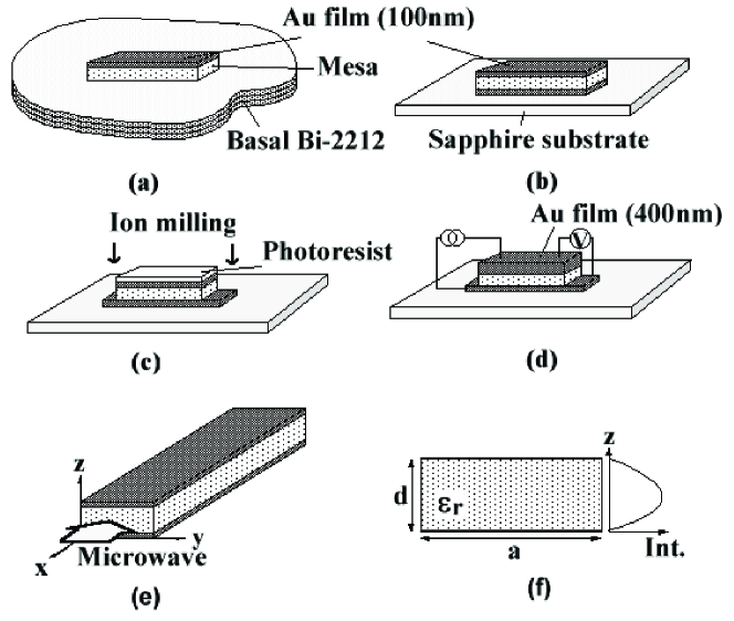
Long quasi-one-dimensional stacks were prepared in the following way. Bi-2212 single crystals were grown by the solid-state-reaction method Kim . A single crystal was first glued on a sapphire substrate using negative photoresist (OMR-83) and was cleaved until an optically clean surface was obtained. Then a 100-nm-thick Au film was thermally deposited on top of the crystal to protect the surface. A mesa with the size of 25 m0.72 m60 nm was then prepared by photolithographic patterning and Ar-ion-beam etching [Fig. 1(a)]. The surface of the patterned mesa was fixed to another sapphire substrate using negative photoresist and the basal part of the mesa was cleaved away. A 100-nm-thick Au film was again deposited on this freshly cleaved crystal surface, leaving a stack of IJJs sandwiched between two Au electrodes [Fig. 1(b)]. A few-m-long portion on both ends of the stack was etched away subsequently to get the bottom Au electrode exposed for -axis transport measurements [Fig. 1(c)]. Finally, 300-nm-thick Au-extension pads were attached [Fig. 1(d)]. This double-side cleaving Wang1 process allows one to prepare a thin stack of IJJs with electrodes on top and bottom, without the basal part. The resulting structure enables one to effectively prevent the fluxons in the basal stack from interfering with the fluxon motion in the mesa. It also provides a transmission line for microwaves so that one can conveniently tune their propagation conditions in the line.
The microwave from a Gunn diode was transmitted through a waveguide and coupled inductively to the stack. The measurements were made in a two-terminal configuration at =4.2 K [Figs. 1(d) and 1(e)] while sweeping the bias current at a several tens of Hz.
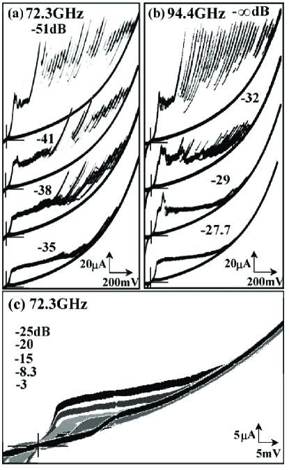
Figs. 2(a) and 2(b) exhibit the evolution of the current-voltage (I-V) characteristics of our stack in the microwave of frequencies 72.3 GHz and 94.4 GHz, respectively, with gradually increasing the irradiation power. The uppermost sets of curves in both figures were obtained for extremely weak power. Each branch in the data is the quasiparticle branch from each IJJ in the stack. Thus the number of branches indicates that the stack contained 40 IJJs, which corresponded to the thickness of 60 nm. Two-terminal measurements gave a finite contact resistance of 1050 ohm from top and bottom contacts manifested as the finite voltage in the first branch of the data. Branches in the low-bias region indicate that about eight junctions had smaller critical current than the other junctions, possibly due to the proximity effect by the Au layers on the stacks close to the top and the bottom Kim or due to any surface degradation during the fabrication. Thus in the remainder of this paper these junctions will be identified as ’the surface junctions’.
The critical current of the inner junctions is 0.1 mA and the normal-state resistance (with the contact resistance subtracted) , determined following the fitting procedure as in Ref. Won , is 33 per junction so that the characteristic voltage is about 3.3 mV (or equivalently 1.6 THz). The plasma frequency turns out to be 30 GHz, determined with junction capacitance of 8.5 pF, the effective dielectric constant 100 (extracted from the quasiparticle return current), and the Josephson penetration depth of 0.34 m. The corresponding Swihart velocity Doh is =6.35104 m/s. The order of magnitude of this rough estimate is in reasonable agreement with the usual value in the mesa structure Heim .
The stack of IJJs sandwiched between two Au layers can be considered as a transmission line for a microwave, where the Bi-2212 stack consisting of extremely thin CuO2 layers (0.3 nm) and insulating Sr-O and Bi-O layers (1.2 nm) acts as an effective dielectric medium as a whole. In the usual mesa structure without wave-confining electrodes microwaves are distributed rather uniformly over the mesa and the basal stack as well. In comparison, specific modes can form along the axis inside our sandwiched stack. Since of a Josephson junction is suppressed with microwave irradiation Doh ; Irie one can monitor the microwave distribution inside a stack by measuring the change in of IJJs. In this sense, the IJJs are utilized as intrinsic EM-wave-detecting sensors inside the stack. For =72.3 GHz in Fig. 2, of all the junctions decreases monotonically with increasing the microwave power from -51 dB up to -3 dB [see Fig. 2(c) also], which is in general agreement with the microwave response observed previously in a mesa structure Doh . By contrast, for =94.4 GHz, of the 3-5 lowest-bias branches from the surface junctions remains almost unchanged for microwave power up to -29 dB, while of the rest of the junctions decreases monotonically as for =72.3 GHz. For power of -29 dB, of the rest of the branches becomes even smaller than that of the surface-junction branches. For =94.4 GHz the of the surface-junction branches starts decreasing only beyond -29 dB.
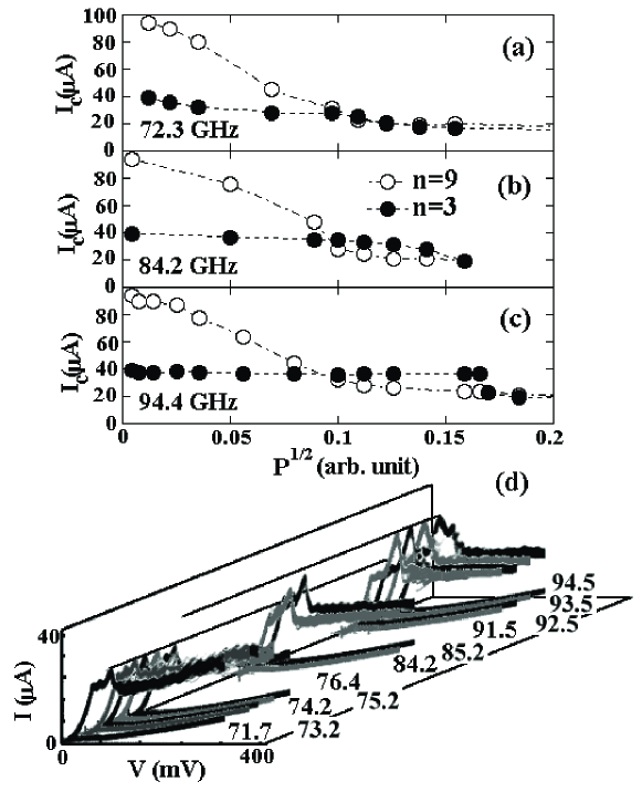
Figs. 3(a)-3(c) show the suppression of of the 3rd () and the 9th () branches for =72.3, 84.2, and 94.4 GHz, respectively, as a function of the square root of the microwave power. is suppressed with irradiation power in a similar manner for all three frequencies. For =72.3 GHz, is suppressed monotonically with power but with a much slower rate than , merging to the value of around 0.1 in an arbitrary unit. For =84.2 GHz, is almost insensitive to the power up to 0.1, above which becomes even smaller than . The trend becomes more conspicuous for =94.4 GHz, where is virtually constant up to 0.17, above which of the two branches merge. For the power in the range 0.17, again becomes smaller than , which is the same phenomenon as discussed in relation with Fig. 2(b). This strongly indicates that the microwave distribution along the axis depends on its frequency. The microwave was almost uniformly distributed across the stack for frequencies below 84 GHz, as evidenced by the overall suppression of as in Fig. 2(a), but it was more intense in the middle of the stack for frequencies above 84 GHz. Fig. 3(d) shows the gradual change in the I-V data for a frequency range of 71.7- 94.5 GHz, taken for varied irradiation power that gives the maximum difference of between the 3rd and the 9th branches for a given frequency. The average values of for the frequency range of 70 GHz and 90 GHz, denoted by two lines in Fig. 3(d), are about 25 and 38 .
The observed results can be explained if the sandwiched rectangular stack behaves as a transmission line Pozar , where a microwave is confined as a standing wave only along the axis. The mode frequency is expressed as =, where is the speed of a microwave in a stack of thickness and (0) is the integer mode number. We assume the frequency GHz is the lowest mode frequency =, because at frequencies below this value a microwave was uniformly distributed inside our stack presumably without forming a mode. For frequencies higher than this value the magnitude of of the two branches were inverted as in Fig. 3(b). This value of gives =1.01104 m/s. Fig. 1(f) shows the schematic distribution of a microwave intensity inside the transmission-line stack, which is consistent with the lowest-mode microwave distribution. For 84.2 GHz, microwaves can transmit through the inner junctions with a standing-wave mode along the axis. The skin depth of an Au layer at , estimated with the measured conductivity of an Au layer 1.31108 mho/m at 4.2 K, was about 150 nm. Since the bottom Au layer was marginally thick to confine the microwave some leak of the microwave out of the transmission line was expected.
One notes that our sandwiched stack is not a simple dielectric medium, but consists of serially connected IJJs. The microwave propagation inside stacked IJJs themselves is governed by the Josephson plasma modes with the mode velocity Kleiner2 , , where is the Swihart velocity and is the number of Josephson junctions in the stack. The mode number varies from to . The lowest mode velocity, , is approximately given as 104 m/s for our stack. This value turns out to be the same order as but about four times higher than , so that the microwave propagation in a transmission line, regarding the stack of IJJs as an insulating medium, is compatible with the lowest-mode plasma propagation in the stacked IJJs. If the finite skin depth is taken into account, however, should be replaced by an effective value, which will give rise to a higher value of . The magnetic field component of microwaves of high irradiation power generates Josephson fluxons in long junction stacks Doh , which give the fluxon-flow resistance as in Fig. 2(c). The observed suppression of , however, occurred before the fluxon-flow state was established.
In conclusion, the microwave distribution inside a stack of IJJs in a transmission-line geometry was investigated by measuring the suppression of the tunneling critical current of the IJJs with varied microwave power at frequencies in the W band. We identified a cut-off frequency for the mode formation. Microwaves were uniformly distributed below the cut-off frequency, but became stronger in the middle of the stack above the cut-off frequency. Thus, to apply a microwave uniformly across an entire stack of IJJs, it may be desirable to design the the stack geometry so as to select measurement frequencies ranging between the Josephson plasma frequency of individual IJJ and the lowest cut-off frequency of the sandwiched stack. The technique used in this study will provide valuable information for the device applications using IJJs in the microwave frequency range.
We wish to thank valuable discussion with and helps from Nam Kim in KRISS and Young-Soon Bae in POSTECH. This work was supported by the National Research Laboratory project administrated by KISTEP.
REFERENCES
References
- (1) R. Kleiner and P. Müller, Phys. Rev. B 49, 1327 (1994).
- (2) H. B. Wang, P. H. Wu and T. Yamashita, Phys. Rev. Lett. 87, 107002 (2001).
- (3) Y. J. Doh, J. H. Kim, H. S. Chang, S. H. Chang, H. J. Lee, K. T. Kim, W. Lee, and J. H. Choy, Phys. Rev. B 63, 144523 (2001).
- (4) A. Irie and G. Oya, Physica C 293, 249 (1997).
- (5) H. B. Wang, Y. Aruga, T. Tachiki, Y. Mizugaki, J. Chen, T. Yamashita and P. H. Wu, Appl. Phys. Lett 75, 2310 (1999).
- (6) R. Kleiner, F. Steinmeyer, G. Kunkel, and P. Müller, Phys. Rev. Lett. 68, 2394 (1992).
- (7) M. Machida, T. Koyama and M. Tachiki, Physica C 362, 16 (2001).
- (8) G. Hechtfischer, R. Kleiner, A. V. Ustinov, and P. Müller, Phys. Rev. Lett. 79, 1365 (1997).
- (9) S. Heim, M Möble, T. claub and R. Kleiner, Supercond. Sci. Technol. 15, 1226 (2002).
- (10) N. Kim, Y.-J. Doh, H.-S. Chang, and H.-J. Lee, Phys. Rev. B 59, 14639 (1999).
- (11) H. Won and K. Maki, Phys. Rev. B 49, 1397 (1994).
- (12) D. M. Pozar, Microwave Engineering (Addison-Wesley Publising Company, Inc., USA, 1990).
- (13) R. Kleiner, T. Gaber, G. Hechtfischer, Phys. Rev. B 62, 4086 (2000).
FIGURE CAPTIONS
Figure 1. (a)-(d) Schematic illustration of the sample fabrication
procedure using the double-side-cleaving technique, (e)
configuration for microwave application, and (f) the intensity
distribution of microwaves inside a stack along the axis.
Figure 2. I-V characteristics of the stack under the
microwave irradiation of frequencies (a) 72.3 GHz and (b) 94.4
GHz, and various irradiation power. (c) I-V characteristics
in the fluxon-flow state at 72.3 GHz for various power ranging
between -25 dB and -3 dB from top to bottom.
Figure 3. (a) The suppression of of the 3rd and the 9th
branches as a function of square root of microwave power. (b)
Gradual change in the I-V data for a frequency range between
71.7 GHz and 94.5 GHz for varied power that gives the maximum
difference of between the 3rd and the 9th branches for a
given frequency. The lines denote the average values of ,
25 and 38 , for the frequency range of 70 GHz and
90 GHz, respectively.