A turnstile electron-spin entangler in semiconductors
Abstract
We propose a single-electron doped quantum dot in a field-effect structure as an optically triggered turnstile for spin-entangled electrons. A short laser pulse excites a charged exciton, whose quantum properties are transferred through tunneling and relaxation to the spin entanglement between electrons in the dot and contact. We identify the pertinent disentanglement mechanisms, and discuss experimental detection and possible application schemes.
pacs:
73.21.La,03.67.-a,71.35.-yDevices based on single quantum systems can provide single quanta. This opens the possibility for the implementation of schemes based on the fundamental laws of quantum mechanics, e.g., quantum cryptography Gisin et al. (2002) or quantum computation. Bennett and DiVincenzo (2000); Bouwmeester et al. (2000) Within the field of semiconductors it was soon realized that quantum dots, Bimberg et al. (1998) sometimes referred to as artificial atoms, are ideal candidates for such challenging future applications, in particular in view of their high compatibility with existing semiconductor technology. Indeed, in the seminal work of Gérard and Gayral Gérard and Gayral (1999) the authors proposed a single quantum dot embedded in a microcavity as a viable single-photon source; the applicability of this scheme was demonstrated experimentally soon after. Michler et al. (2000); Santori et al. (2001); Moreau et al. (2001) An important technological improvement is due to Yuan et al. Yuan et al. (2002) who succeeded to replace the optical triggering by an electrical one.
A reversed approach was recently pursued by Zrenner et al., Zrenner et al. (2002) where the authors used a quantum-dot photodiode as an optically triggered single-electron turnstile: a short laser-pulse coherently excites an exciton in a quantum dot embedded in a field-effect structure; if the structure is properly designed, such that tunneling occurs on a much shorter timescale than radiative decay, the electron-hole excitation of the quantum dot decays into a separated electron and hole within the contacts, which is detected as the photocurrent. Within this scheme it thus becomes possible to transfer optical excitations in a deterministic way to electrical currents.
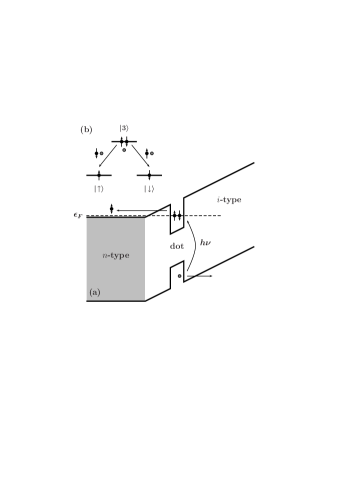
In this paper we exploit this finding to propose a device which allows the optically triggered creation of a spin-entangled electron pair. The proposed structure (Fig. 1a) is identical to the one used by Zrenner et al., Zrenner et al. (2002); Beham et al. (2001) with the only exception that the dot is initially populated by a single surplus electron; this can be achieved by applying an external bias voltage such that an electron is transferred from a nearby -type reservoir to the dot, Warburton et al. (2000); Findeis et al. (2001) where further charging is prohibited because of the Coulomb blockade. Optical excitation of this structure then results in the excitation of a charged exciton, i.e., a complex consisting of two electrons and a single hole; Warburton et al. (2000); Hartmann et al. (2000); Findeis et al. (2001) appropriate tuning of light polarization and frequency allows to selectively excite the charged-exciton groundstate, where the two electrons have opposite spin orientations. Since within the field-effect structure the charged exciton is not a stable configuration, in a consequent step one electron and hole will tunnel out from the dot to the nearby contacts; here, the system can follow two pathways, where either the electron in the dot has spin-up and the one in the reservoir spin-down orientation or vice versa. According to the laws of quantum mechanics, the total state of the system thus becomes a superposition of these two configurations; as will be proven below, in this state the electron spins are maximally entangled. Thus, the proposed device is an optically triggered turnstile for spin-entangled electrons, which could be used in future quantum information applications to establish entanglement between spatially separated sites.
In a sense, our scheme is similar to the proposal of Benson et al. Benson et al. (2000) in which entangled photons are created in the cascade decay of a biexciton. However, in the system of our present concern additional difficulties arise because the tunnel-generated electron and hole do not propagate freely (as photons would in the corresponding scheme) but are subject to interactions in the contact. The resulting scatterings of the entangled particles hamper a straightforward interpretation of the functionality of the proposed device and call for a careful theoretical analysis. It is the purpose of this paper to provide a comprehensible theory accounting for the complete cascade process of: the buildup of three-particle coherence through tunneling; the swapping of quantum coherence to spin entanglement through dephasing and relaxation in the reservoirs; and finally the process of disentanglement through spin-selective scatterings. Since the main emphasis of our work is on the identification of the basic schemes underlying the buildup and decay of entanglement, we rely on a simplified description scheme of environment interactions, which will allow us to derive analytic expressions throughout.
Our model system comprises (Fig. 1b): the spin-degenerate electron groundstates and the charged-exciton groundstate in the dot (with energies and , respectively); the electron and hole states in the reservoir, described by the usual field operators and (energies and ) with labeling the quantum numbers (e.g., wavevector and band index), and we have explicitly indicated the electron spin. The Hamiltonian of the system without interactions thus reads
| (1) |
Since we are dealing with an open system (i.e., system interacting with its environment) we have to adopt a density-matrix description. Walls and Millburn (1995); Scully and Zubairy (1997) Let us assume that initially the electron spin direction is undetermined, i.e., the corresponding density matrix is a mixture . When at time the dot is subject to an unpolarized optical -pulse Zrenner et al. (2002) it will be excited to state . Hence, the initial density matrix is (although the proposed scheme would also work for charged-exciton occupancies less than one, as discussed below).
For the system’s time evolution we employ a master-equation framework of Lindblad form Walls and Millburn (1995); Scully and Zubairy (1997)
| (2) |
within which scatterings are described in the usual Markov and adiabatic approximations. In Eq. (2) the ’s are the Lindblad operators which account for the different scattering channels.
Tunneling.—For low temperatures and early times we can safely neglect phonon processes and radiative decay in the dot, and tunneling becomes the only relevant scattering channel. Quite generally, the question whether combined electron-hole tunneling dominates over separate tunneling (as we will assume) depends on the design of the structure. In Ref. Beham et al., 2001 the authors measured tunneling lifetimes between 29 and 330 ps, where the exact value strongly depends on the internal electric field; Larkin and Vagov (2003) alternatively, it might be advantegeous to use type-II quantum dots Janssens et al. (2002) where the hole is only Coulomb bound and much shorter tunneling lifetimes could be achieved. However, such details are not crucial to our study and the only relevant assumptions are: first, all tunneling processes are independent of spin; second, since the hole enters with a high excess energy into the contact it immediately suffers an inelastic scattering, which guarantees that tunneling is an irreversible process. In our calculations the latter point is taken into account by tracing over the hole degrees of freedom in the reservoir and neglecting terms . Within this framework and assuming tunneling matrix elements independent of and , we can solve Eq. (2) through an unraveling of the master equation Plenio and Knight (1998) to obtain: sif
| (3) |
with: the total tunneling rate; the electron and hole density-of-states in the reservoir; the time evolution operator in the reservoir; and the density matrix after tunneling. In the spirit of the quantum-jump approach, Plenio and Knight (1998) in Eq. (3) the first term can be interpreted as the conditional density matrix for no tunneling (which decays with ) whereas the second term is the conditional evolution after tunneling. The corresponding density matrix is obtained from Plenio and Knight (1998) , where is the Lindblad operator for tunneling and the denominator ensures , which gives:
| (4) |
Here, is the Fermi energy of the -type reservoir; is a cutoff energy due to the kinematics of the tunneling process; ; and a spin-orientation antiparallel to . Eq. (4) is an important and non-trivial result. First, it demonstrates that despite the incoherent nature of tunneling and hole relaxation the electron system can be described in terms of wavefunctions; we note here in passing that the detection of the hole would even allow to purify this wavefunction, Bouwmeester et al. (2000) which might be of relevance when initially is not equal to . Second, a closer inspection of Eq. (4) reveals that the spin part is a maximally entangled state of the electrons in the dot and reservoir. We emphasize that this maximal entanglement is independent of the spin basis, which guarantees that our scheme is not deteriorated by possible polarization anisotropies of the dot states (fine-structure splittings).
Dephasing and relaxation.—After tunneling the system propagates in presence of scatterings, as described by in Eq. (3). Quite generally, we assume that the orbital degrees of the reservoir electron are subject to much stronger interaction channels (e.g., phonons) than the spin degrees, as evidenced by the long measured spin lifetimes (ns) in -doped semiconductors. Kikkawa and Awschalom (1998) For that reason, let us first consider an elastic electron scattering which does not depend on spin, i.e., Lindblad operators of the form with the scattering rate. Unraveling the corresponding master equation in an analogous fashion to Eq. (3), we again recover a conditional evolution for no scattering (which decays with ) and a remainder which describes the effects of scattering; here, the density matrix after scattering becomes: sif
| (5) |
In comparison to Eq. (4) the density matrix of Eq. (5) is diagonal in , i.e., the elastic scattering has led to a destruction of the phase coherence (i.e., dephasing). However, the spin part still shows the same degree of entanglement, where similar conclusions would apply for inelastic but spin-independent scatterings. Thus, the decay of an optically excited charged-exciton indeed generates a robust spin entanglement between the electron in the dot and reservoir.
Disentanglement.—We finally comment on the process of disentanglement. In fact, any scattering channel which couples with unequal strength to the spins (or affects only one spin orientation) is responsible for such entanglement decay. Naively, one could expect that a preferential scattering of, e.g., spin-up electrons in the reservoir would establish a stronger degree of spin-down population in the dot; however, this is not supported by our calculations which show that any spin-selective scattering com forces the spins with equal probability to one of the two orientations. Thus, to experimentally detect spin entanglement in the proposed scheme both electrons have to be monitored. This could be achieved by introducing a ferromagnetic contact at the interface of the -doped region, which acts as a spin filter for the reservoir electron. Transmission across the interface corresponds to a spin measurement which also determines the spin orientation of the electron in the quantum dot. The resulting state could be probed by a second, time-delayed optical -pulse whose polarization is chosen such that it selectively excites the –3 transition. Thus, the transmission into the ferromagnet is accompanied by the optical excitation of a second charged exciton in the dot (which consecutively is transferred to an electric current). On the other hand, if the second optical pulse arrives before disentanglement, the dot density matrix is a mixture and optical excitation occurs only with a 50%-probability, which results in a distinctly different noise characteristics of the photocurrent.
In conclusion, we have proposed a scheme for an optically triggered spin entanglement of electrons in semiconductors. It consists of a single-electron doped quantum dot embedded in a field-effect structure. Optical excitation of an additional electron-hole pair (charged exciton) is transferred through tunneling to a photocurrent, where the spins of the electrons in the dot and reservoir are maximally entangled. We have discussed that this entanglement is robust against dephasing and relaxation processes which are not spin-selective, and thus benefits from the long spin lifetimes in semiconductors. The proposed device might be useful in future quantum information applications to establish entanglement between spatially separated sites; there, it might be advantageous to replace the -type reservoir by quantum wires (for a natural realization of such combined dot-wires structures see, e.g., Ref. Hartmann et al., 2000). Finally, in contrast to other proposal for spin entanglement in semiconductors Engel et al. (2002) our scheme allows the creation of spin-entangled electrons on demand (through optical triggering).
U. H. is grateful to Jaroslav Fabian for helpful discussions. This work has been supported in part by the Austrian science fund FWF under project P15752.
References
- Gisin et al. (2002) N. Gisin, G. Ribordy, W. Tittel, and H. Zbinden, Rev. Mod. Phys. 74, 145 (2002).
- Bennett and DiVincenzo (2000) C. H. Bennett and D. P. DiVincenzo, Nature 404, 247 (2000).
- Bouwmeester et al. (2000) D. Bouwmeester, A. Ekert, and A. Zeilinger, eds., The Physics of Quantum Information (Springer, Berlin, 2000).
- Bimberg et al. (1998) D. Bimberg, M. Grundmann, and N. Ledentsov, Quantum dot heterostructures (John Wiley, New York, 1998).
- Gérard and Gayral (1999) J. M. Gérard and B. Gayral, Journal of Lightwave Technology 17, 2089 (1999).
- Michler et al. (2000) P. Michler, A. Kiraz, C. Becher, W. V. Schoenfeld, P. M. Petroff, L. Zhang, E. Hu, and A. Imamoglu, Science 290, 2282 (2000).
- Santori et al. (2001) C. Santori, M. Pelton, G. Solomon, Y. Dale, and Y. Yamamoto, Phys. Rev. Lett. 86, 1502 (2001).
- Moreau et al. (2001) E. Moreau, I. Robert, L. Manin, V. Thierry-Mieg, J. M. Gérard, and I. Abram, Phys. Rev. Lett. 87, 183601 (2001).
- Yuan et al. (2002) Z. Yuan, B. E. Kardynal, R. M. Stevenson, A. J. Shields, C. J. Lobo, K. Cooper, N. S. Beattie, D. A. Ritchie, and M. Pepper, Science 295, 102 (2002).
- Zrenner et al. (2002) A. Zrenner, E. Beham, S. Stufler, F. Findeis, M. Bichler, and B. Abstreiter, Nature 418, 612 (2002).
- Beham et al. (2001) E. Beham, A. Zrenner, F. Findeis, M. Bichler, and G. Abstreiter, Appl. Phys. Lett. 79, 2808 (2001).
- Warburton et al. (2000) R. J. Warburton, C. Schäflein, D. Haft, F. Bickel, A. Lorke, K. Karrai, J. M. Garcia, W. Schoenfeld, and P. M. Petroff, Nature 405, 926 (2000).
- Findeis et al. (2001) F. Findeis, M. Baier, A. Zrenner, M. Bichler, G. Abstreiter, U. Hohenester, and E. Molinari, Phys. Rev. B 63, 121309(R) (2001).
- Hartmann et al. (2000) A. Hartmann, Y. Ducommun, E. Kapon, U. Hohenester, and E. Molinari, Phys. Rev. Lett. 84, 5648 (2000).
- Benson et al. (2000) O. Benson, C. Santori, M. Pelton, and Y. Yamamoto, Phys. Rev. Lett. 84, 2513 (2000).
- Walls and Millburn (1995) D. F. Walls and G. J. Millburn, Quantum Optics (Springer, Berlin, 1995).
- Scully and Zubairy (1997) M. O. Scully and M. S. Zubairy, Quantum optics (Cambridge University Press, Cambridge, UK, 1997).
- Larkin and Vagov (2003) I. Larkin and A. Vagov, Phys. Rev. B 67, 115318 (2003).
- Janssens et al. (2002) K. L. Janssens, B. Partoens, and F. M. Peeters, Phys. Rev. B 65, 233301 (2002).
- Plenio and Knight (1998) M. B. Plenio and P. L. Knight, Rev. Mod. Phys. 70, 101 (1998).
- (21) C. Sifel and U. Hohenester (unpublished).
- Kikkawa and Awschalom (1998) J. M. Kikkawa and D. D. Awschalom, Phys. Rev. Lett. 80, 4313 (1998).
- (23) In our calculations we use Lindblad operators of the form , with the scattering rate and an angle determining the degree of asymmetry.
- Engel et al. (2002) H.-A. Engel, P. Recher, and D. Loss, Solid State Commun. 119, 229 (2002).