Coherent Quantum Dynamics of a Superconducting Flux Qubit
Abstract
We have observed coherent time evolution between two quantum states of a superconducting flux qubit comprising three Josephson junctions in a loop. The superposition of the two states carrying opposite macroscopic persistent currents is manipulated by resonant microwave pulses. Readout by means of switching-event measurement with an attached superconducting quantum interference device revealed quantum-state oscillations with high fidelity. Under strong microwave driving it was possible to induce hundreds of coherent oscillations. Pulsed operations on this first sample yielded a relaxation time of 900 nanoseconds and a free-induction dephasing time of 20 nanoseconds. These results are promising for future solid-state quantum computing.
It is becoming clear that artificially fabricated solid-state devices of macroscopic size may, under certain conditions, behave as single quantum particles. We report on the controlled time-dependent quantum dynamics between two states of a micron-size superconducting ring containing billions of Cooper pairs (1). From a ground state in which all the Cooper pairs circulate in one direction, application of resonant microwave pulses can excite the system to a state where all pairs move oppositely, and make it oscillate coherently between these two states. Moreover, multiple pulses can be used to create quantum operation sequences. This is of strong fundamental interest because it allows experimental studies on decoherence mechanisms of the quantum behavior of a macroscopic-sized object. In addition, it is of great significance in the context of quantum computing (2) because these fabricated structures are attractive for a design that can be scaled up to large numbers of quantum bits or qubits (3).
Superconducting circuits with mesoscopic Josephson junctions are expected to behave according to the laws of quantum mechanics if they are separated sufficiently from external degrees of freedom, thereby reducing the decoherence. Quantum oscillations of a superconducting two-level system have been observed in the Cooper pair box qubit using the charge degree of freedom (4). An improved version of the Cooper pair box qubit showed that quantum oscillations with a high quality factor could be achieved (5). In addition, a qubit based on the phase degree of freedom in a Josephson junction was presented, consisting of a single, relatively large Josephson junction current-biased close to its critical current (6,7).
Our flux qubit consists of three Josephson junctions arranged in a superconducting loop threaded by an externally applied magnetic flux near half a superconducting flux quantum [(8); a one-junction flux-qubit is described in (9)]. Varying the flux bias controls the energy level separation of this effectively two-level system. At half a flux quantum, the two lowest states are symmetric and antisymmetric superpositions of two classical states with clockwise and anticlockwise circulating currents. As shown by previous microwave spectroscopy studies, the qubit can be engineered such that the two lowest eigenstates are energetically well separated from the higher ones (10). Because the qubit is primarily biased by magnetic flux, it is relatively insensitive to the charge noise that is abundantly present in circuits of this kind.
The central part of the circuit, fabricated by electron beam lithography and shadow evaporation of Al, shows the three in-line Josephson junctions together with the small loop defining the qubit in which the persistent current can flow in two directions, as shown by arrows (Fig. 1A). The area of the middle junction of the qubit is times the area of the two outer ones. This ratio, together with the charging energy and the Josephson energy of the outer junctions (where and are their critical current and capacitance, respectively), determines the qubit energy levels (Fig. 2A) as a function of the superconductor phase across the junctions (Fig. 1B). Close to , the loop behaves as a two-level system with an energy separation of the eigenstates and described by the effective Hamiltonian , where are the Pauli spin matrices, is the level repulsion, and (where is the qubit maximum persistent current) (11).
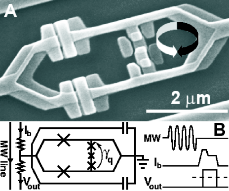
The sample is enclosed in a gold-plated copper shielding box kept at cryogenic temperatures T = 25 mK (kBT ). The qubit is initialized to the ground state simply by allowing it to relax. Coherent control of the qubit state is achieved by applying resonant microwave excitations on the microwave (MW) line (Fig. 1B), thereby inducing an oscillating magnetic field through the qubit loop. The qubit state evolves driven by a time-dependent term in the Hamiltonian where F is the microwave frequency and is the energy-modulation amplitude proportional to the microwave amplitude. This dynamic evolution is similar to that of spins in magnetic resonance. When the MW frequency equals the energy difference of the qubit, the qubit oscillates between the ground state and the excited state. This phenomenon is known as Rabi oscillation. The Rabi frequency depends linearly on the MW amplitude (12-14).
Readout is performed with an underdamped superconducting quantum interference device (SQUID) with a hysteretic current-voltage characteristic in direct contact with the qubit loop (Fig. 1A). The mutual coupling is relatively large because of the shared kinetic and geometric inductances of the joint part enhancing the qubit signal. After performing the qubit operation, a bias current pulse is applied to the SQUID (15). The pulse consists of a short current pulse of length 50 ns followed by a trailing plateau of 500 ns (Fig. 1B). During the current pulse, the SQUID either switches to the gap voltage or stays at zero voltage. The pulse height and length are set to optimize the distinction of the switching probability between the two qubit states, which couple to the SQUID through the associated circulating currents. Because the readout electronics has a limited bandwidth of 100 kHz, a voltage pulse of 50 ns pulse is too short to be detected. For that reason the trailing plateau is added, with a current just above the retrapping current of the SQUID. The whole shape is adjusted for maximum readout fidelity. The switching probability is obtained by repeating the whole sequence of reequilibration, microwave control pulses and readout typically 5000 times.

When the SQUID bias current is switched on, the circulating current in the SQUID changes. This circulating current, coupled to the qubit through the mutual inductance, changes the phase bias of the qubit by an estimated amount . Consequently the phase bias at which the quantum operations are performed is different from the phase bias at readout. This can be very useful because at the phase bias near , where the qubit is least sensitive to flux noise, the expectation values for the qubit circulating current are extremely small. The automatic phase bias shift can be used to operate near and to perform readout at a bias with a good qubit signal (11). Care must be taken that the fast shift remains adiabatic and that the whole sequence is completed within the relaxation time.

The average SQUID switching current versus applied flux shows the change of the qubit ground-state circulating current (Fig. 2B). Here, the pulse amplitude is adjusted such that the averaged switching probability is maintained at 50. A step corresponding to the change of qubit circulating current was observed (around the dashed line). The relative variation of 2.5 of is in agreement with the estimation based on the qubit current and the qubit-SQUID mutual inductance .
The relevant two energy levels of the qubit were first examined by spectroscopic means. Before each readout, a long microwave pulse (1 s) at a series of frequencies was applied to observe resonant absorption peaks/dips each time the qubit energy separation adjusted by changing the external flux coincides with the MW frequency (10). The dots in Fig. 2C are measured peak/dip positions, obtained by varying , whereas the continuous line is a numerical fit produced by exact diagonalization (compare Fig. 2A) giving an energy gap GHz. The curves in Fig. 2, B and C, are plotted against the change in external flux from the symmetry position indicated by the dotted line. In agreement with our numerical simulations, the step (Fig. 2B) is shifted away from the symmetry position of the energy spectrum (Fig. 2C) by a phase bias shift . The step reflects the external-flux dependence of the qubit circulating current at (after the shift), whereas the spectrum reflects at (before the shift) (16).

Next, we used different MW pulse sequences to induce coherent quantum dynamics of the qubit in the time domain. For a given level separation , a short resonant MW pulse of variable length with frequency was applied. Together with the MW amplitude, the pulse length defines the relative occupancy of the ground state and the excited state. Corresponding switching probability was measured with a fixed-bias current pulse amplitude. We obtained coherent Rabi oscillations of the qubit circulating current for a frequency GHz and three different values of the MW power (Fig. 3). The variation in switching probability is around 60, indicating that the fidelity in a single readout is of that order. By varying , we verified the linear dependence of the Rabi frequency on the MW amplitude, a key signature of the Rabi process (Fig. 3B). The oscillation pattern can be fitted to a damped sinusoid. For relatively strong driving (Rabi period below 10 ns), decay times up to 150 ns are obtained. This large decay time resulted in hundreds of coherent oscillations at large microwave power.
The Rabi scheme also allows the study of the state occupancy relaxation. This can be done by applying a coherent pulse for full rotation of the qubit into the excited state and varying the delay time before readout. Experiments performed at GHz gave an exponential decay with relaxation time ns.
As a next step we measured the undriven, free-evolution dephasing time by performing a Ramsey interference experiment (17) as follows. Two pulses, whose length is determined from the Rabi precession presented above, are applied to the qubit. The first pulse creates a superposition of the and states. If the microwave frequency is detuned by away from resonance, the superposition phase increases with a rate , in the frame rotating with the MW frequency . After a varying delay time, we apply a second pulse to measure the final and state occupancy via the switching probability. The readout shows Ramsey fringes with a period , as in Fig. 4A, where GHz and MHz. The dots represent experimental data, whereas the continuous line is an exponentially damped sinusoidal fitting curve, yielding a free-evolution dephasing time ns. Note that the oscillation period of 4.5 ns agrees well with .
Additional information on the spectral properties of the decohering fluctuations can be obtained with a modified Ramsey experiment. By inserting a pulse between the two pulses (Fig. 4B), we obtain a spin-echo pulse configuration. The role of the pulse is to reverse the noise-driven diffusion of the qubit phase at the midpoint in time of the free evolution. Dephasing due to fluctuations of lower frequencies should be cancelled by their opposite influence before and after the pulse (18). Spin-echo oscillations (Fig. 4B) are taken under the same conditions as the Ramsey fringes, but are here recorded as a function of the pulse position. The period (2.3 ns) is half that of the Ramsey interference. We measured the decay of the maximum spin-echo signal (i.e. with the pulse in the center) versus the delay time between the two pulses. The data can be fitted to a half-Gaussian (not shown) with a decay time ns.
We conclude that with the present device and setup, the dephasing time ns, as measured with the Ramsey pulses, is much shorter than the relaxation time ns. Dephasing is probably caused by a variation in time of the qubit energy splitting, due to external or internal noise. A likely source is external flux noise, which can be reduced in the future. The present qubit could not be operated at the symmetry point where the influence of flux noise is minimal (5), presumably as the result of an accidentally close SQUID resonance (19). Other possible noise sources are thermal, charge, critical current and spin fluctuations. From estimations of the Johnson noise in the bias circuit (20,21), we find a contribution that is several orders of magnitude weaker.
For strong driving, Rabi oscillations persisted for times much longer than . This constitutes no inconsistency. The dependence of the Rabi period on the detuning, due to fluctuations of the qubit energy , is weak when the Rabi period is short. The fact that coherence is only marginally improved by the pulse in the spin-echo experiment seems to indicate the presence of noise at frequencies beyond 10 MHz. Further analysis and additional measurements are needed.
These first results on the coherent time evolution of a flux qubit are very promising. The already high fidelity of qubit excitation and readout can no doubt be improved. Quite likely it is also possible to reduce the dephasing rate. Taken together, these results establish the superconducting flux qubit as an attractive candidate for solid-state quantum computing.
References
- (1) A. J. Leggett, A. Garg, Phys. Rev. Lett. 54, 857 (1985).
- (2) M. A. Nielsen, I. L. Chuang, Quantum Computation and Quantum Information (Cambridge Univ. Press, Cambridge, 2000).
- (3) Y. Makhlin, G. Sch n, A. Shnirman, Rev. Mod. Phys. 73, 357 (2001).
- (4) Y. Nakamura, Yu. A. Pashkin, J.S. Tsai, Nature 398, 786 (1999).
- (5) D. Vion et al., Science 296, 886 (2002).
- (6) Y. Yu, S. Han, X. Chu, S.-I. Chu, Z. Wang, Science 296, 889 (2002).
- (7) J. M. Martinis, S. Nam, J. Aumentado, C. Urbina, Phys. Rev. Lett. 89, 117901 (2002).
- (8) J. E. Mooij et al., Science 285, 1036 (1999).
- (9) J. R. Friedman, V. Patel, W. Chen, S.K. Tolpygo, J.E. Lukens, Nature 406, 43 (2000).
- (10) C. H. van der Wal et al., Science 290, 773 (2000).
- (11) The two opposite persistent currents states, depicted by arrows in Fig. 1A, describe the basis of Pauli spin matrices. Using the notation , the qubit eigenstates can be written as and and the expectation values of the corresponding circulating currents as .
- (12) I. I. Rabi, Phys. Rev. 51, 652 (1937).
- (13) M. Grifoni, P. H nggi, Phys. Rep. 304, 229 (1998).
- (14) In the frame rotating at the MW frequency , at the symmetry point (), the Rabi precession is around an axis perpendicular to x axis with a frequency [with as in (11)].
- (15) During the qubit initialization and control, the SQUID bias current is set to zero and, as a result of the SQUID symmetry, the qubit is decoupled from the external current noise to first order. At , small external noise current flows equally in the two branches of the SQUID even in the presence of the circulating current in the SQUID. See also (21).
- (16) A part of the energy spectrum is missing, because the readout is not efficient around the step and thus the spectroscopy signal is weak.
- (17) N. F. Ramsey, Phys. Rev. 78, 695 (1950).
- (18) E. L. Hahn, Phys. Rev. 80, 580 (1950).
- (19) In the present device, GHz was rather close to the SQUID plasma frequency designed to be 2 GHz (at ). This could be a possible explanation for the absence of coherent oscillations for .
- (20) Lin Tian, S. Lloyd, T.P. Orlando, Phys. Rev. B 65, 144516 (2002).
- (21) C.H. van der Wal, F.K. Wilhelm, C.J.P.M. Harmans, J.E. Mooij, Eur. Phys. J. B 31, 111 (2003).
- (22) We thank R. N. Schouten, J. B. Majer, A. Lupascu, and K. Semba, for experimental help and discussion; D. Esteve and C. Urbina for valuable input; and D. Vion, A. Aassime, C. H. van der Wal, A. C. J. ter Haar, T. Orlando, S. Lloyd, M. Grifoni, F. K. Wilhelm, L. Vandersypen, and P.C.E. Stamp for fruitful discussions. Supported by the Dutch Foundation for Fundamental Research on Matter (FOM), the European Union SQUBIT project, and the U.S. Army Research Office (grant DAAD 19-00-1-0548).