Radiation-induced oscillatory-magnetoresistance as a sensitive probe of the zero-field spin splitting in high mobility GaAs/AlGaAs devices
Abstract
We suggest an approach for characterizing the zero-field spin splitting of high mobility 2D electron systems, when beats are not readily observable in the Shubnikov-de Haas effect. The zero-field spin splitting and the effective magnetic field seen in the reference frame of the electron are evaluated from a quantitative study of beats observed in radiation-induced magnetoresistance oscillations
pacs:
73.21.-b,73.40.-c,73.43.-f; Journal-Ref: Phys. Rev. B 69, 193304 (2004)The recent discovery1 of novel non-equilibrium zero-resistance states under photo-excitation might be counted as the latest surprise in the physics of the 2-Dimensional Electron System (2DES),1 ; 2 which has provided topics of enduring interest such as the integral and fractional quantum Hall effects (QHE).3 Unlike quantum Hall systems, where zero-resistance states coincide with a quantized Hall effect,3 ; 4 these new states are characterized by an ordinary Hall effect in the absence of backscattering.1 ; 2 The remarkable phenomenology1 ; 2 has generated much excitement due to the possibility of identifying a new mechanism for artificially inducing vanishing electrical resistance, while obtaining a better understanding of QHE plateau formation and zero-resistance in the 2DES.5 ; 6
While the reasons mentioned above have motivated theoretical interest,6 one might wonder whether the phenomena might also serve as an improved probe in a 2D-problem with a functional interest. Here, we suggest that radiation-frequency-independent beats observed in the microwave-induced magnetoresistance might serve as a sensitive indicator of the zero-field spin splitting and the associated spin-orbit ”Zeeman magnetic field” in the 2DES. The resulting technique could help to advance research involving the measurement, control, and utilization of the effective magnetic field that appears in the reference frame of the electron, in the high mobility GaAs/AlGaAs 2DES.7 ; 8
Mobile 2D electrons can experience, in their rest frame, an effective magnetic field that develops from a normal electric field at the semiconductor heterojunction interface due to the so-called Bychkov-Rashba effect.9 As this magnetic field can, in principle, be controlled by an electrical gate, it has been utilized in the design of novel spin based devices.8 The Bychkov-Rashba term, proportional to the electron wavevector , is believed to account for most of the observed Zero-field Spin Splitting (ZFSS) in the narrow gap 2DES.8 In the 2DES realized in wider gap GaAs/AlGaAs, a Bulk Inversion Asymmetry (BIA) contribution to the ZFSS, provides an additional effective magnetic field as B 0.10 ; 11 ; 12 ; 13 ; 14 Although theory has suggested that the BIA term is stronger than the Bychkov-Rashba term in the GaAs/AlGaAs heterostructure 2DES,14 ZFSS in n-type GaAs/AlGaAs is not easily characterized because its signature is often difficult to detect using available methods. This has hindered spintronics research in the GaAs/AlGaAs system, which provides the highest mobility 2DES.
Typical investigations of ZFSS in the 2DES look for beats in the Shubnikov-de Haas (SdH) oscillations that originate from dissimilar Fermi surfaces for spin-split bands.15 ; 16 ; 17 However, the applicability of this approach requires the observability of SdH oscillations at very weak magnetic fields. In GaAs/AlGaAs heterostructures with two dimensional electrons, this is not easily realized, even in high quality material. In addition, other mechanisms can, in principle, provide similar experimental signatures.16 ; 17 ; 18 Thus, a need has existed for simple new methods of investigating the spin-orbit interaction in the 2DES characterized by a small zero-field spin splitting, to supplement the SdH, Raman scattering, Electron Spin Resonance (ESR) and weak localization based approaches.16 ; 19 ; 20 ; 21 In this light, the approach proposed here has the advantages of simplicity and improved sensitivity because the ZFSS ( 20 eV) is determined through a comparison of the spin splitting with an easily tunable, small energy scale set by the photon energy ( 200 eV), unlike, for example, the SdH approach which relates the ZFSS ( 20 eV) to differences between two (spin split) Fermi surfaces with energy of order 10 meV in GaAs/AlGaAs.
Experiments were carried out on standard GaAs/AlGaAs heterostructure devices. Upon slow cooling in the dark, the 2DES exhibited a low electron density, (4.2 K) . Subsequent brief illumination by a LED produced (4.2 K) and a mobility (1.5 K) up to . Lock-in based four-terminal measurements of the resistance and the Hall effect were carried out with the sample mounted inside a waveguide, as it was excited with microwaves over the frequency range 27 120 GHz. The microwave power, estimated to be less than 1 mW, was set at the source and then reduced using variable attenuators.
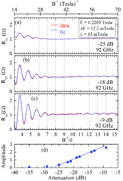
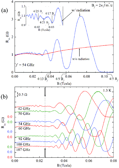
Fig. 1(a) illustrates the magnetoresistance observed with (w/) and without (w/o) microwave excitation, in the high mobility condition. Without radiation, weak magnetoresistance is characterized by the absence of the SdH effect to B = 0.11 Tesla at 1.3 K (see Fig. 1(a)). Excitation of the specimen with electromagnetic waves induces oscillations in ,22 ; 23 and a zero-resistance-state over a broad B-interval in the vicinity of 0.1 Tesla.1 ; 2 Fig. 1 (a) shows that the three deepest resistance minima occur about (4/5) , (4/9) , and (4/13) , where = 2. In addition, a non-monotonic variation in the amplitude of the resistance oscillations produces a beat at low (see Fig. 1(a), inset).2 In Fig. 1(b), resistance data are shown for a number of microwave frequencies. These data show, for the first time, that the beat in the oscillatory resistance remains at a fixed with a change in .
A lineshape study was carried out in order to characterize these oscillations. Over a narrow -window above the beat, the data could be fit with an exponentially damped sinusoid: = , where is the amplitude, is the damping factor, and is the resistance oscillation frequency.22 A lineshape that included the superposition of two such waveforms: = = where = and = , proved unsatisfactory in modelling the beat data because this lineshape includes a phase reversal through the beat, unlike experiment. Thus, we consider = , which can realize beats without phase reversal.
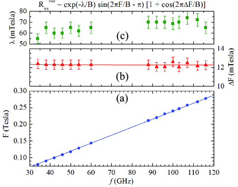
Fig. 2 (a) - (c) illustrate data obtained at a fixed , as a function of the power attenuation factor. Also shown, is a fit to the data, using the lineshape = . Inspection shows good agreement between data and fit, and a comparison of Fig. 2 (a), (b), and (c) shows a monotonic increase in the amplitude of the oscillations with increasing power level, that is reproduced by the fit parameter, , see Fig. 2(d). The oscillation period, , where = , served to renormalize the inverse field axis, as in the lower abscissa, see Fig. 2(c). The data-plot vs. / shows that nodes occur in the vicinity of = , and = , where =1,2,3,… while minima transpire about = .
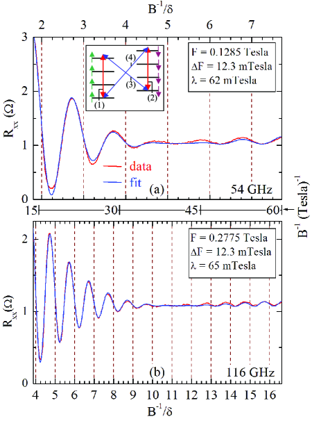
Representative data and fit at a pair of , see Fig 3, show that this lineshape also describes the data obtained at widely spaced . A summary of the fit parameters, , , and , is presented in Fig. 4. The noteworthy features in Fig. 4 are: (i) increases linearly with , (see Fig. 4(a)).1 (ii) The beat frequency, 12.3 mTesla, is independent of (see Fig. 4(b)), consistent with Fig. 1(b). And, (iii) the damping parameter , 65 mTesla, is also approximately independent of (see Fig. 4(c)). Here, the exponential damping could be rewritten in a Dingle form, = , where and represent a finite frequency broadening-temperature and lifetime, respectively, and is approximately 1. Note that = 65 mTesla (Fig. 4(c)) corresponds to = 66 mK.22
The lineshape, = , in our model can be understood by invoking four distinct transitions between Landau subbands near the Fermi level, as cartooned in the inset of Fig.3. Here, the spin-orbit interaction helps to remove the spin degeneracy of Landau levels as B 0. Thus, the terms (1) and (2) represent spin preserving inter Landau level transitions, and the terms (3) and (4) represent spin-flip transitions. If the oscillations originating from these terms have equal amplitude and share the same , then one expects a superposition of four terms: , which is the lineshape that has been used here.
Here, the nearly equal amplitudes for the spin-flip and the spin-preserving transitions are attributed to the occurrence of mechanisms such as the Bychkov-Rashba effect and the bulk-inversion symmetry,9 ; 11 which produce spin precession about an in-plane magnetic field.24 Under the influence of such spin-orbit mechanisms, the effective magnetic field direction experienced by electrons changes with scattering, and this changing magnetic field environment helps to modify spin orientation with respect to the applied magnetic field. A component of the microwave magnetic field, which is oriented perpendicular to the static magnetic field, can also serve to flip spin.
Thus, beats observed in the radiation-induced resistance oscillations appear as a consequence of a zero-field spin splitting, due to the spin-orbit interaction.8 ; 9 ; 10 ; 11 ; 12 ; 13 ; 14 ; 15 ; 16 ; 17 ; 19 ; 20 One might relate to the ZFSS by identifying the radiation-frequency change, , that will produce a similar change in , i.e., , where is the beat frequency, and is the rate of change of with the radiation frequency (see Fig. 4(a)). Then, the ZFSS corresponds to = 5.15 GHz or = = 21 eV. From a study of the ESR at high magnetic fields, Stein et al.20 reported a ZFSS of 7.8 GHz for = cm-2, which complements our result for cm-2. Theory suggests that, in the GaAs/AlGaAs heterostructure 2DES, both the BIA and the Bychkov-Rashba terms have similar magnitudes, even as the BIA makes the stronger contribution; the upper bound for the total ZFSS is 80eV.14
Our ESR study near filling factor = 1 in the quantum Hall regime showed that the electron spin resonance field, , varied as = 0.184 Tesla/GHz, which implies an effective Zeeman magnetic field = [ = 0.95 Tesla. As the effective magnetic field due to the Bychkov-Rashba term is oriented perpendicular to both the direction of electron motion and the normal of the 2DES, while the BIA contribution lies along the direction of motion of electrons,14 this evaluation of is associated with the magnitude of the vector obtained by adding these terms. Although this estimate for the 0 Zeeman magnetic field appears, at first sight, to be rather large by laboratory standards, the small g-factor in GaAs/AlGaAs heterostructures implies a small corresponding spin splitting, = 21 eV, in comparison to the Fermi energy ( 10 meV). Thus, SdH beats would be expected below the lowest B ( 0.2 Tesla at 1.3 K) at which SdH oscillations were observed in this material.
In summary, we have suggested that beats in the radiation-induced magnetoresistance oscillations in GaAs/AlGaAs 2DES heterostructures might serve as a new probe of the zero-field spin splitting in the 2DES. This method could serve to simply track changes in the spin-orbit interaction that result from the controlled modification of the device structure, and this might prove helpful for spintronics research based in the GaAs/AlGaAs system.7 ; 8
References
- (1) R. G. Mani, J. H. Smet, K. von Klitzing, V. Narayanamurti, W. B. Johnson, and V. Umansky, Nature (London) 420, 646 (2002); Phys. Rev. Lett. 92, 146801 (2004).
- (2) M. A. Zudov, R. R. Du, L. N. Pfeiffer and K. W. West, Phys. Rev. Lett. 90, 046807 (2003).
- (3) The Quantum Hall Effect, 2nd Ed. edited by R. E. Prange and S. M. Girvin, (Springer-Verlag, New York, 1990).
- (4) D. C. Tsui, H. L. Stormer, and A. C. Gossard, Phys. Rev. B 25, 1405 (1982).
- (5) R. Fitzgerald, Phys. Today 56 (4), 24 (2003)
- (6) J. C. Phillips, Sol. St. Comm. 127, 233 (2003); A. C. Durst, S. Sachdev, N. Read, and S. M. Girvin, Phys. Rev. Lett. 91, 086803 (2003); A. V. Andreev, I. L. Aleiner, and A. J. Millis, Phys. Rev. Lett. 91, 056803 (2003); P. W. Anderson and W. F. Brinkman, cond-mat/0302129; J. Shi and X. C. Xie, Phys. Rev. Lett. 91, 086801 (2003); A. A. Koulakov and M. E. Raikh, Phys. Rev. B 68, 115324 (2003); F. S. Bergeret, B. Huckestein, and A. F. Volkov, Phys. Rev. B 67, 241303 (2003); V. Ryzhii, Sov. Phys. - Sol. St. 11, 2078 (1970).
- (7) S. A. Wolf, D. Awschalom, R. Buhrman, J. Daughton, S. von Molnar, M. Roukes, A. Chtchelkanova, and D. Treger, Science 294, 1488 (2001).
- (8) S. Datta and B. Das, Appl. Phys. Lett. 56, 665 (1990).
- (9) Y. A. Bychkov and E. I Rashba, J Phys. C. 17, 6039 (1984).
- (10) G. Dresselhaus, Phys. Rev. 100, 580 (1955).
- (11) L. M. Roth, Phys. Rev. 173, 755 (1968).
- (12) G. Lommer, F. Malcher, and U. Rossler, Phys. Rev. Lett. 60, 728 (1988); P. Pfeffer and W. Zawadzki, Phys. Rev. B 59, R5312 (1999); P. Pfeffer, ibid. 59, 15902 (1999).
- (13) R. Eppenga and M. F. H. Schuurmans, Phys. Rev. B. 37, 10923 (1988).
- (14) E. A. De Andrada e Silva, G. C. La Rocca, and F. Bassani, Phys. Rev. B 50, 8523 (1994).
- (15) B. Das, D. C. Miller, S. Datta, R. Reifenberger, W. P. Hong, P. K. Bhattacharya, J. Singh, and M. Jaffe, Phys. Rev. B 39, 1411 (1989).
- (16) P. Ramvall, B. Kowalski, and P. Omling, Phys. Rev. B 55, 7160 (1997).
- (17) A. C. H. Rowe, J. Nehls, R. A. Stradling, and R. S. Ferguson, Phys. Rev. B 63, 201307 (2001).
- (18) T. H. Sander, S. N. Holmes, J. J. Harris, D. K. Maude, and J. C. Portal, Phys. Rev. B 58, 13856 (1998).
- (19) B. Jusserand, D. Richards, G. Allan, C. Priester, and B. Etienne, Phys. Rev. B 51, 4707 (1995).
- (20) D. Stein, K. von Klitzing, and G. Weimann, Phys. Rev. Lett. 51, 130 (1983).
- (21) J. B. Miller, D. M. Zumbuhl, C. M. Marcus, Y. B. Lynda-Geller, D. Goldhaber-Gordon, K. Campman, and A. C. Gossard, Phys. Rev. Lett. 90, 076807 (2003).
- (22) R. G. Mani, J. H. Smet, K. von Klitzing, V. Narayanamurti, W. B. Johnson, and V. Umansky, Bull. Am. Phys. Soc. 46, 972 (2001); in Proceedings of the 26th International Conference on the Physics of Semiconductors, Edinburgh, 2002, edited by A. R. Long and J. H. Davies, IOP Conf. Proc. No. 171, (Institute of Physics, Bristol, 2003) H112; cond-mat/0303034 (unpublished); cond-mat/0305507 (unpublished).
- (23) M. A. Zudov, R. R. Du, R. R. Simmons, and J. L. Reno, Phys. Rev. B. 64, 201311 (2001).
- (24) A. Khaetskii and Yu. Nazarov, Phys. Rev. B 61, 012639 (2000)