Non-destructive, dynamic detectors for Bose-Einstein condensates
Abstract
We propose and analyze a series of non-destructive, dynamic detectors for Bose-Einstein condensates based on photo-detectors operating at the shot noise limit. These detectors are compatible with real time feedback to the condensate. The signal to noise ratio of different detection schemes are compared subject to the constraint of minimal heating due to photon absorption and spontaneous emission. This constraint leads to different optimal operating points for interference-based schemes. We find the somewhat counter-intuitive result that without the presence of a cavity, interferometry causes as much destruction as absorption for optically thin clouds. For optically thick clouds, cavity-free interferometry is superior to absorption, but it still cannot be made arbitrarily non-destructive . We propose a cavity-based measurement of atomic density which can in principle be made arbitrarily non-destructive for a given signal to noise ratio.
pacs:
03.75.Fi,32.80.-t, 32.80.PjI Introduction
This paper presents a comprehensive analysis of non-destructive, dynamic measurement schemes of Bose Einstein condensates (BEC) in both interferometric and non-interferometric configurations. The dynamic nature of these detectors is essential if they are to be used for feedback to the condensate. Optical detection of the condensate causes heating through photon absorption and spontaneous emission, and this prompted the development of nondestructive techniques that detect the phase shift imparted on a laser beam rather than the absorption of that beam Ketterle1996 ; Ketterle1999 ; Lye1999 ; Aspect1999 ; Hulet1997 ; Milburn1998 ; Walker2001 .
It is therefore necessary to compare the signal to noise ratio (SNR) achievable by each technique for a given absorption rate. This constraint changes both the optimum operating conditions for many techniques as well as the optimal choice of detection scheme in different parameter regimes. We find that no current technique can be made arbitrarily sensitive for fixed absorption, and propose a new detection scheme based on an optical cavity that has a sensitivity under this criterion that scales with the square root of the finesse.
These detection schemes are based on fast photo-detectors operating at the shot noise limit. In contrast to all existing techniques based on CCD cameras, these schemes allow for real-time density measurements with high temporal resolution that are appropriate for the implementation of feedback to the condensate. This feedback will initially allow mode-locking of the BEC, and eventually allow control of its quantum state that will in turn determine the properties of an atom laser beam Wiseman2002 ; Thomsen2001 . The development of these detectors and feedback is important if we are to realize the pumped atom laser and through it, the full potential of quantum atom optics.
We find, contrary to popular belief, that the SNR in interferometric measurements cannot be increased arbitrarily by increasing laser power and increasing detuning from atomic resonance. Further, we find that for thin clouds subject to a fixed heating by the probe beam, fluorescence measurements can be more sensitive than single-pass interferometric measurements such as those that have been performed. This is surprising given that fluorescence is based on the destructive phenomenon of absorption and spontaneous emission whereas interferometry is sensitive to the phase shift of the forward scattered photons, suggesting interferometry would always be the less invasive technique. For each technique, we derive expressions for the minimum observable change in the column density of the condensate as a function of heating and bandwidth for optically thick and thin clouds. The techniques we discuss are compatible with optical amplitude/phase and spatial squeezing allowing sub-shot noise and sub-diffraction limited resolution in future implementations Treps2002 ; Mckenzie2002 .
The requirements on dynamic detectors are best illustrated by consideration of the Gedanken experiment sketched in Fig. 1. Here, we consider an atom laser beam produced by coherent outcoupling from a condensate that may be pumped, although it will be unpumped in early investigations laser1 ; laser2 ; laser3 ; laser4 ; laser5 . The atom beam and condensate are probed by light beams, and information regarding the noise and fluctuations of the condensate and the atom beam is fed back to the condensate. The requirements on the design of the two detectors shown are quite different. For the dynamic detection of the atom laser beam with detector 1, there is no non-destructive criterion Esslinger2002 . This can be seen by analogy with the detection of photons from a laser beam. Nothing could be more destructive to an optical beam than a photodiode, photomultiplier or CCD camera. The photons are destroyed and an electron is excited to a new state and recorded. For example, atoms outcoupled from a metastable helium BEC can be counted using a multi-channel plate with good time resolution and high quantum efficiencyLeduc2001 ; Aspect2001 . No such detector exists for neutral ground state atoms. The design of such a detector will be the subject of a future paper.
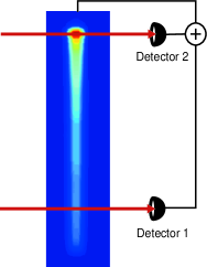
It might be thought that feedback from detector 1 would be sufficient to stabilize the atom laser. Any classical noise brought about by motion of the condensate in the trap could probably be compensated by feedback from the atom laser beam flux. In the absence of classical noise, Wiseman and Thomsen have recently concluded that a pumped atom laser will have a linewidth dominated by the effect of the atomic interaction energy, which turns fluctuations in the condensate number into fluctuations in the condensate phase Thomsen2001 . They further conclude that feedback from the atom laser beam flux will not improve the linewidth, and suggest using dispersive imaging of the condensate and feeding back to the phase of the condensate via the trap bias or via a far-detuned laser beam. This role is fulfilled by detector 2 and the feedback loop shown in Fig. 1. Detector 2 is the more difficult of the two detectors to design and implement, and we concentrate on the non-destructive dynamic detection of the condensate in this paper.
The optimization of a measurement scheme, whether it be interferometry, absorption or fluorescence is strongly influenced by the restrictions imposed by the physics of the system being probed. Gravity-wave interferometers, for example, are limited by laser power and saturation of the detectors. Optimization of a shot-noise limited (SNL) phase measurement with these restrictions requires operation near a dark port with equal power in the interferometer arms. This design is used in all current gravity wave detectors under development Gray1995 ; Caves1981 ; Loudon1981 ; McClelland1993 . In contrast, the non-destructive criterion for the probing of a condensate that we apply in this paper leads to unbalanced powers in the interferometer arms. As another example, optimization of the SNR for the non-destructive interferometric detection of condensates while holding the ratio of probe to local oscillator power constant leads to increasing signal to noise with increasing detuning Lye1999 ; Aspect1999 . In many of the designs we discuss here, the local oscillator is passed around the condensate. Although total absorption by the BEC is fixed, total power in the interferometer is not, and the SNR becomes independent of detuning from resonance at least for optically thin clouds. The following sections contain a detailed analysis of shot-noise limited measurements optimized for the non-destructive, dynamic detection of Bose Einstein condensates.
II Dynamic, non-destructive absorption and fluorescence.
II.1 Absorption
In a single beam absorption measurement, a probe with incident power passes through the atoms. The probe beam receives a phase shift and is partially absorbed, with the power transmitted described by . Both the phase shift and absorption coefficient, , scale linearly with the column density, , the density integrated along the beam direction. Stabilization of the BEC via feedback requires detecting a small fluctuating component of the column density, which may be on a large, slowly changing column density background. We explicitly define both components to correctly optimize the detection in the limits of both optically thick and thin clouds.
| (1) |
Ultimately, we want a sensitive detector that can detect very small fluctuations. We assume . Setting describes the specific case of detecting the full BEC, in the limit of thin clouds.
The absorption and phase shift are given by:
| (2) |
| (3) |
where is the resonant absorption cross-section, assuming we are probing a closed transition. The detuning given in units of half atomic linewidth, is .
The optical power transmitted through the BEC is detected on a phase-insensitive photodetector. The detector responsivity, , relates the incident optical power to the current produced by the photodiode. The quantum efficiency, , is related to the responsivity through .
| (4) |
The desired signal is the AC component of , which is selected with an appropriate filter on the current. The resulting RMS signal, , is:
| (5) |
We assume the noise is dominated by shot noise from the laser, which translates to current noise on the photodetector Yariv1985 ,
| (6) |
where is the bandwidth of the detection system.
| (7) |
Taking the ratio of Eqs. (5) and (7), and setting , gives the SNR for a SNL dynamic absorption measurement:
| (8) |
II.1.1 Adding a non-destructive criterion
A continuous ‘non-destructive’ measurement sets an upper limit on the average power absorbed, , by the BEC.
| (9) | |||||
For an optically thin cloud at steady state, this absorbed power is equal to the power emitted by the process of spontaneous emission. This can be converted directly to the number of photons emitted per atom every second. It is the recoil from these spontaneous emission events which will destroy and dephase the BEC. As the BEC becomes optically thick, reabsorption of the emitted photons becomes an issue, and the total number of recoils caused by the absorption of a single photon from the probe laser beam will depend on the mean free path of the photons in the medium as well as the geometry of the trapped atoms. In this regime, every photon absorbed by the BEC will do far more damage than a single recoil event, and the restriction on the amount of power absorbed by the BEC for a non-destructive measurement will need to be more stringent.
Including the non-destructive criterion above in the SNR:
| (10) |
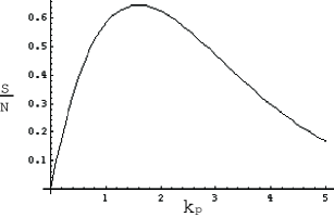
We optimize the function , shown in Figure 2. The function reaches a maximum value of 0.65 when , which corresponds to approximately 80% of the power absorbed. At larger absorption, the total amount of power absorbed increases, but the sensitivity of the absorption to small fluctuations decreases as the BEC becomes optically thick.
The maximum absorption possible occurs on resonance, when . If , the optimum value can be chosen by detuning the probe beam appropriately. If , should be set to its maximum value, , by putting the probe on resonance. This leads to two different optimum SNR equations in the limits of optically thin and thick clouds:
| (11) |
| (12) |
Setting the SNR to unity gives the smallest measurable change in column density from absorption:
| (13) |
| (14) |
We might be more interested in fixing , the photon absorption rate of an individual atom. This can be found from the power absorbed by the condensate:
| (15) |
where is the cross-sectional area of the beam, and therefore is the number of atoms in the beam. The smallest measurable change in column density is therefore given by
| (16) |
| (17) |
II.2 Fluorescence
The signal from fluorescence is the same as for absorption, with the exception that only 1-10% of the emitted photons would typically be collected, reducing the signal by the collection efficiency .
The total photocurrent from the emitted photons collected on the photodiode is:
| (18) |
As before, the desired signal is the AC component of , which is selected with a highpass filter on the current. The current shot noise is related to the average of , as described by (6). The resulting RMS signal and noise are given by:
| (19) | |||||
| (20) |
Taking the ratio of these results yields the SNR. The non-destructive criterion is included by rewriting in terms of . Setting gives:
| (21) |
This shows that the SNR for fluorescence will be at a maximum in the limit of thin clouds, when . For sensitivity to small changes in the BEC, we would expect to detune to the linear thin cloud regime.
| (22) |
The smallest measurable change in column density from fluorescence is found by setting the SNR to unity.
| (23) |
In terms of the rate of absorption per atom, this is given by
| (24) |
Fluorescence has the same maximum SNR (for a given ) regardless of whether the BEC is optically thick or thin to resonant light. An important caveat is that in the optically thick case, the reabsorption of emitted photons will usually require a lower for the measurement to be non-destructive.
In the limit of an atomic cloud that is optically thick to resonant light, the ratio of optimized SNL fluorescence to optimized SNL absorption is approximately the collection efficiency. In an actual fluorescence experiment the collection efficiency will be much less than one, and absorption is the better option for an optically thick cloud. In the optically thin limit, the ratio of optimized SNL fluorescence to optimized SNL absorption equals . Fluorescence is the most sensitive technique in the case of very thin clouds, when .
III Dynamic non-destructive dispersive detection
III.1 Separated beam path interferometry
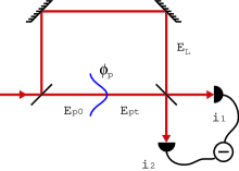
We analyze the generic separated beam path interferometer shown in Fig. 3. A local oscillator with power passes outside the BEC, where is the proportionality constant relating the square of the electric field to the power in the optical field. A probe with incident power passes through the atoms, experiencing the phase shift and absorption described in Sec. II.1.
The current from the photodetectors, where + and refer to the two ports of the interferometer, is:
| (25) |
The total phase shift, , is composed of the assumed stable phase difference between the probe and local oscillator beams, , and the AC and DC components of the phase shift from the BEC. The DC phase shifts are combined by setting .
| (26) | |||||
In order to maintain a constant operating point at , the interferometer would need to be locked at this point. The bandwidth of the locking loop should be sufficiently fast to track the slow decay, which for a typical BEC will be at most Hz. The bandwidth must also be much slower than the trap oscillation frequency, where we expect our lowest signal frequencies.
The best SNR is achieved with homodyne detection, detecting at both ports and subtracting the currents, as will be shown in Section IV. The desired signal is the AC component of which can be selected with an appropriate filter on the current. The resulting RMS signal, , is:
| (28) |
We assume the noise is dominated by shot noise from the laser, which is related to current noise on the photodetector by Eq. 6. The current noise from each photodetector is added in quadrature:
| (29) | |||||
As we will see later in the analysis, the power in the probe beam is limited by the non-destructive requirement to a value far less than the available laser power, even for large detunings. By inspection, optimizing equation (30) subject to the restriction on the probe power yields the optimum operating points of and . This operating point is halfway up a fringe, with far greater power in the local oscillator than the probe beam. This contrasts with an interferometer that is designed to measure a small phase shift without this restriction, which is limited by the total available laser power, and has optimal SNR when there is equal power in the two interferometer paths.
At the optimum operating point, the SNR is
| (31) |
Note that the optimum SNR is independent of power in the local oscillator for a SNL measurement provided the shot noise dominates the detector noise in a real detector, and provided the power of the local oscillator is far greater than that of the probe.
We rewrite the SNR including the non-destructive criterion limiting absorption from Eq. 9. The details of the atom-light interaction are included using Eqs. (2) and (3). We combine the column density and absorption coefficient as the dimensionless variable .
| (32) |
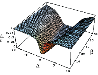
The SNR is shown in Figure 4, normalized to one. The maximum occurs in the far detuned limit where the atomic sample is optically thin. These two limits are satisfied when . In this limit, the optimum SNR is :
| (33) |
Setting the SNR to unity gives the smallest measurable change in column density from an optimized non-destructive interferometer.
| (34) |
In terms of the absorption rate per atom, this is given by
| (35) |
The SNR in an optimized interferometer is independent of the laser power and detuning. The smallest signal that can be detected depends only on the column density of the BEC, the bandwidth of the measurement, and on the stringency of the non-destructive criterion required for the particular measurement.
In the limit of optically thin clouds on resonance (), optimized interferometry has exactly the same signal to noise as optimized absorption. As the column density of the BEC increases to the optically thick limit on resonance, the optimum SNR from absorption drops by a factor of , while interferometry maintains the same maximum for both limits. In this limit, absorption has the same sensitivity as fluorescence (except for a factor of collection efficiency). Interferometry is fundamentally superior to absorption or fluorescence for measuring BECs with Ketterle1999 .
III.2 Frequency modulation spectroscopy.
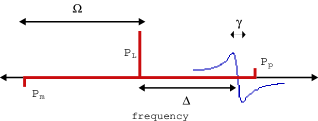
Frequency modulation spectroscopy (FMS), a single beam and therefore geometrically stable technique, has previously been proposed by our group and the CNRS group as a non-destructive dynamic detector of BECs Lye1999 ; Aspect1999 . Instead of a separate local oscillator that passes around the BEC, FMS relies on a frequency shifted local oscillator, far detuned from resonance relative to the probe beam, that passes through the BEC. In this section, we investigate the important parameters in a FMS measurement, and consider whether it is possible with available detectors to use FMS as a non-destructive probe for a BEC feedback experiment.
In FMS, the single beam that passes through the BEC has a carrier, , at frequency, , and two sidebands, and , at frequencies and respectively Bjorklund1983 as shown in Fig. 5. The signal, the sum of the two beat signals between the carrier and each of the sidebands, is detected at the modulation frequency, . With no BEC present, there is zero signal as the two sidebands are out of phase and the beats cancel. With a BEC present, the three components of the beam receive different phase shifts due to the frequency dependent dispersion of the atoms described by , and , and the beat signals no longer cancel. In the limit of small phase shifts, the amplitude of the net beat is proportional to the column density. FMS not only has the advantages of geometric stability, it has zero background thus is insensitive to classical laser noise, and the large modulation frequency enables detection in a quiet part of the laser intensity spectrum as well as being far above any 1/f electronic noise.
After optimizing FMS in the following analysis, we find that even in the best case scenario, the shot noise is well below the detector noise for a typical PIN diode detector. This best case occurs when we are detecting the full BEC, and we have the minimum bandwidth possible to measure trap frequencies, B = 100 Hz. In contrast to all other techniques analyzed in this paper, we optimize the FMS signal relative to detector noise in the following analysis.
The optical power incident on the photodetector is proportional to the square of the electric field averaged over an optical cycle:
| (36) |
The incident optical power produces a current from the photodetector. Only the terms at the modulation frequency, , are of interest. We assume , and write the sidebands as a (as yet unspecified) fraction of the carrier power, . We rewrite the equation in terms of the total power, .
| (37) |
The signal is mixed down to DC with a radio frequency local oscillator with waveform . Assuming the mixer operates as an ideal multiplier, the output current is . As the gain is identical for signal and noise, we have set it equal to one. A lowpass filter is used to remove frequencies of and above to give an RMS voltage of:
| (38) |
Maximum signal occurs when . We assume we are operating at large laser detuning and that the phase shifts from the BEC are small, .
| (39) |
The phase shift dependence on detuning is included from equation (3), with detuning defined relative to the carrier frequency, as shown in figure 5. Again, we assume large detunings, . The modulation frequency and the detuning is measured in units of half atomic linewidths.
| (40) |
The signal is rewritten in terms of the ratio of the detuning to the modulation frequency, .
| (41) |
The sidebands and the carrier all contribute to absorption and all three components must be included when fixing the average power absorbed to a non-destructive level.
| (42) |
The absorption dependence on detuning is included from equation (3).
| (43) |
Substituting into equation (41):
| (44) |
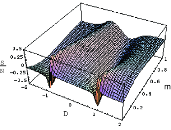
The FMS signal from (44), normalized by dividing through by , is shown in figure 6 versus and . The signal has an optimum value of 0.5 at and . This is similar to the situation shown in figure 5.
| (45) |
The optimum signal increases with modulation frequency which will be limited by the bandwidth of the detector. PIN diodes are the most suitable detectors with their combination of high bandwidth and large dynamic range. The photodiode current will have noise at the modulation frequency, , which will be transferred through the mixer.
| (46) |
Inserting the values , W, , and B=100 Hz NewFocus :
| (47) |
Unlike separated beam path interferometry, FMS improves in sensitivity with increasing detuning and from atomic resonance and increasing modulation frequency. Although FMS offers the advantages of simplicity and robustness, it is limited to relatively low local oscillator powers by the speed of current detectors, and by the non-destructive criterion placed on the measurement. It seems unlikely that it could be pushed into a SNL regime. Despite its suitability for many dynamic measurements, it would appear unlikely to be able to compete with separated beam path interferometry in feedback applications.
III.3 Resonant Interferometry
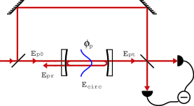
In this section, we analyze a resonant cavity as a non-destructive detector of Bose-Einstein condensates. The cavity is included in one arm of a Mach-Zender interferometer, as shown in Fig. 7, enabling an interferometric homodyne measurement using the same optimum operating points identified in the earlier analysis in Sec III.1. High finesse cavities have been used in the strong coupling regime to both detect and control the motion of single atoms RempeKimble . We are working in the weak coupling regime with the sole aim of extracting information about the condensate.
The ratio of the amplitude of the reflected field to that of the field incident on a mirror is . Similarly, is the ratio of the amplitude of the transmitted field to that of the incident field. The single pass phase shift is denoted . The reflected, transmitted and circulating electric fields of the cavity are given by the equations below.
| (48) |
In every pass through the cavity, some of the probe light will be absorbed by the BEC. We assume that the finesse is dominated by losses at the mirrors rather than by losses in the BEC. That is, where for a high finesse cavity. Although the power absorbed is fixed for a non-destructive measurement, the absorption coefficient is not, and can be reduced by increasing the detuning. For a standard BEC, where , and at a maximum detuning of Hz, the finesse will be limited to , much larger than any achievable experimental finesse.
The single pass phase shift consists of a DC phase shift from the BEC, a small fluctuating phase shift from the BEC, and a phase shift from the cavity itself. The cavity is operated on resonance, with the combined DC phase shifts locked to zero. The phase shift of the probe beam is most sensitive to changes in the BEC column density at this operating point.
The sum of the transmitted and reflected power at a mirror must equal the incident power, allowing us to rewrite . We assume that the fluctuating BEC phase is very small. The change in the transmitted field due to the fluctuations in the BEC is:
| (49) |
The phase shift from the BEC is increased by a factor of twice the finesse compared to the phase shift in a non-resonant interferometer. This extra factor can be substituted directly into the optimized non-resonant interferometer SNR, Eq. (31).
| (50) |
The non-destructive limit on the power absorbed will depend on the circulating power in the cavity, (for optically thin clouds). On cavity resonance, the circulating power is:
| (51) |
As we found earlier, the signal to noise is optimised when the probe beam is far detuned from atomic resonance, and the BEC is optically thin. In this limit, the atomic phase shift and absorption coefficient simplify to and . Including the non-destructive criterion and the details of the atom-light interactions in the SNR gives:
| (52) |
and
| (53) |
or, in terms of the atomic absorption rate,
| (54) |
The sensitivity in a non-destructive resonant interferometric measurement is enhanced by a factor of the square root of the finesse compared to a non-resonant interferometer.
IV Quantum analysis of interferometric detection
In this section we re-examine interferometric detection using a quantized treatment of the light. With the use of classical light, non-destructive detection is ultimately limited by the shot noise of the detected light. This is an important practical limit, but it is not a fundamental one that restricts all possible imaginable detection schemes. Although this limit can be pushed out by increasing the finesse of a resonant interferometer, there will be restrictions on the maximum usable finesse as we discuss in section V. We demonstrate that the limits to detection can be improved with the use of a non-classical light source, and show that in all cases balanced homodyne detection, with a very small proportion of the laser power going through the atomic cloud, will provide the best SNR for a given absorption rate by the BEC.
Consider the interferometer described in section III.3 with squeezed light as one of the inputs. We model this interferometer with input fields described by the annihilation operators and incident on a beam splitter with reflectivity . This setup is pictured in Fig. 8.
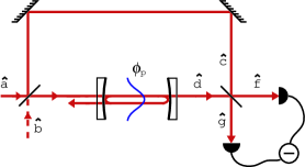
We assume that the field is a large-amplitude coherent state and that the field is a (possibly squeezed) state with very low mean amplitude. The two input fields combine to give fields and in the arms. The field experiences a phase shift due to the atoms in the resonant cavity:
| (55) | |||||
The phase difference , in this discussion, contains both the systematic phase shift between the probe and the local oscillator and the phase shift due to the atoms. There are many equivalent energy-conserving choices for these beamsplitter relations, but their only effect is to include an extra constant phase in . The second beamsplitter recombines these fields into two new fields and :
| (56) | |||||
The input field operators are approximated as the sum of a classical coherent amplitude and a zero-mean quantum operator:
| (57) | |||
where and have the same commutation relations as the input fields, . We also introduce the quadrature basis for the two input fields:
| (58) | |||||
Keeping only terms proportional to or larger and assuming that the input field is a strong local oscillator, we determine the number of photons at each detector. and ,
| (59) | |||||
| (60) | |||||
These photon numbers are directly proportional to the photocurrents received from the detectors, with the operators averaging to zero expectation value, but having non-zero variance. The product of the variances obey the inequality due to Heisenberg’s Uncertainty Principle. For shot-noise limited coherent lasers, these terms each have a variance of unity.
Summing these intensities, we find that
| (61) |
which is simply the intensity and shot noise of the input local oscillator.
In order to find the ideal operating point for detection, we set . is the systematic phase shift between the fields and , which depends on the phase difference between the different paths of the interferometer and the cavity detuning, as well as the choice of beam-splitter relations. is the phase shift induced by the atoms. In the limit of small signal, , we can make the approximations and , and readily extract the signal to noise ratio.
IV.1 Single port detection
Assuming that the dominant noise source is the shot noise of the light, and ignoring the finite quantum efficiency of the photodetectors, we can assume that the photocurrent is directly proportional to the instantaneous photon number with identical statistics. We examine the signal received from a single photodetector by taking the expectation value of the number operator (either Eq.(IV) or Eq.(IV)). We see that it has a constant component and a signal proportional to . The noise is determined by examining the variance of the number operator. The three noise terms must be added in quadrature, with Hz for a shot-noise limited input laser. We ignore the DC component, which in practice can be achieved either through modulation or by a difference measurement. For unit bandwidth, the signal to noise is given by
| (64) |
where
| (65) | |||||
This has a maximum value for operating near a dark port. The restriction on absorption by the BEC has not been included. We are guided by the fact that is equal to the square root of the photon flux incident on the cavity. Following section (III.3) and using equations (2),(3) and (9), we can make the substitution:
| (66) | |||||
where is the spontaneous emission rate of the atoms caused by the absorption, is the cross-sectional area of the beam, and is the atomic cross-section as previously defined. Using this substitution in Eq.(64) and maximizing the SNR for choice of and , we find that in the presence of squeezed light, the best operating parameters appear to be unchanged, but this corresponds to such a weak beam entering the interferometer that the signal will be dominated by detector noise rather than the shot noise of the light. This means that squeezed light will not usefully enhance the SNR for single port detection. This is not the case for systems without a non-destructive criterion, as they do not have a cap on the total circulating power in the cavity.
In the absence of squeezing, the SNR for unit bandwidth is given by
| (67) |
This limiting SNR assumes the detector has perfect efficiency and the absorption by the condensate is negligible. This is valid in the high finesse and high detuning limits.
IV.2 Homodyne measurement
When an interferometer is used to measure a phase shift, it is clearly wise to measure a large phase shift if this can be arranged. The phase shift from the BEC is proportional to the square root of the absorption rate, which is the main measure of the ”destructiveness”, and our measurement is constrained in that we must detect as small a phase shift as possible. Without this constraint, single port detection has the same theoretical maximum SNR as a homodyne measurement. Including the constraint, we find that this is no longer true. A better maximum SNR can be obtained by detecting both output ports of the interferometer and examining the difference photocurrent, removing the component of the shot noise which is correlated on each port. In operator form, the photon difference is:
| (68) | |||
The signal and noises are determined in the same manner as single port detection discussed above. After substituting the expression in Eq.(66) for to determine the SNR as a function of atomic spontaneous emission rate , we find that for a unit bandwidth it is given by
| (69) |
This SNR is maximal when and , corresponding to balanced detection with only a very small fraction of the input laser power going through the atomic sample. In this limit, we find that the SNR has a theoretical maximum:
| (70) |
which, by comparison with Eq.(67), is a factor of larger than the optimal result for a single port detection. Both of these results show that with squeezing of the appropriate quadrature of the vacuum input to the interferometer, an arbitrarily high SNR can be achieved independent of the finesse of the cavity. Such an experiment would be difficult to demonstrate. It is only recently that squeezing has been used to improve the sensitivity of any interferometer Mckenzie2002 .
V Comparison of techniques and technical limitations in real detectors
V.1 Comparison of shot-noise limited techniques
| Measurement Scheme | () | () |
|---|---|---|
| Fluorescence | ||
| Absorption (thick) | ||
| Absorption (thin) | ||
| Interferometry | ||
| Resonant Interferometry |
Table 1 shows a summary of the smallest measurable change in column density using optimized absorption, fluorescence, interferometry, and resonant interferometry in a shot-noise limited measurement. Fluorescence, interferometry, and resonant interferometry have the same optimum operating point for all BEC column densities, while absorption has the added complication that its optimum changes depending on whether the BEC is optically thick or thin when probed with resonant light. In the limit of an optically thick cloud, optimized absorption has the same sensitivity as fluorescence, except for the factor of collection efficiency. However in this limit, interferometry or resonant interferometry are the superior detectors to either absorption or fluorescence. In the limit of an optically thin cloud, the optimum absorption sensitivity is the same as for non-resonant interferometry, but in this limit fluorescence is now the most sensitive technique. Either way, absorption is never the most sensitive technique, and at best is equally sensitive for a small range of measurements where is slightly less than one. Resonant and non-resonant interferometry scale the same with respect to column density, however a resonant interferometer is a factor of more sensitive. The ratio of minimum from resonant interferometry and fluorescence shows how the ideal technique depends on the BEC column density:
| (71) |
In the limit of very thin clouds, , fluorescence is the most sensitive technique, otherwise resonant interferometry has the highest fundamental sensitivity. Resonant interferometry is the only technique that can, at least theoretically, be improved arbitrarily for fixed absorbed power. The sensitivity of the other techniques are limited by the experimental requirements on non-destructiveness, bandwidth, and the column density of the BEC.
V.2 Technical limitations with real detectors
We have assumed in all but one of the detection schemes presented, that laser shot noise dominates all other noise sources. Shot-noise limited sources and detection at the shot noise limit is standard technology in quantum optics labs around the world. Of more serious concern in interferometric measurements are geometrical phase shifts brought about by the acoustic vibration of beam splitters and mirrors. Here FMS, as a single beam method, is superior to all other interferometric techniques. In FMS, however, the local oscillator passes through the BEC and it is far more destructive than separated beam path interferometry. It is in the design of separated beam path methods and resonant interferometry that geometric phase shifts must be carefully considered.
In Section III.1, it was shown that the signal to noise in a separated beam path interferometer is independent of laser detuning provided the detuning is sufficiently large that the cloud is optically thin. In addition to this restriction, we must avoid lensing of the light beam due to the condensate. Both can be achieved by operating at small phase shifts. The present model, although it provides scaling and best case signal to noise, completely neglects lensing effects on the propagation of the Gaussian probe beam. Excessive lensing will make signals difficult if not impossible to interpret due to imperfect mode matching in separated beam path interferometers and multimode behaviour in a resonant cavity. The effect will be particularly acute in a high finesse cavity and will probably limit the maximum useful finesse. Nonetheless, interferometric measurements will be least sensitive to vibration if the phase shift from the condensate is made as large as possible by operating as close to atomic resonance consistent with the restrictions above. This highlights an important difference between many interferometric measurements where small phase shifts are detected with high intra-cavity power, and a non-destructive BEC measurement where low probe powers are used and comparatively large phase shifts can be detected.
In addition to the choice of detuning, a sensitive interferometer will need to be acoustically and vibrationally isolated and have its operating point locked in order to minimize geometrical phase shifts. There is a wealth of information in the literature on locking, and we discuss here only a few points pertinent to measurements on BECs. Unlike many phase objects, atoms are a resonant system, and this can be used to advantage. Two phase coherent probe beams can be injected into the interferometer with different detunings from atomic resonance. The beam closer to resonance will carry more information on the condensate and less on geometric shifts. The reverse is true for the beam detuned further from resonance. Comparison of the two signals will allow locking of the operating point across the entire signal band providing greater immunity to vibration than would be possible on measurements of a non-resonant phase object.
Although the high finesse cavity is more sensitive than non-resonant interferometry by a factor of the square root of the finesse, this sensitivity comes at the price of increased susceptibility to vibration. Geometrical instabilities are amplified by the finesse. A high degree of vibration isolation, locking over the entire signal bandwidth, and monolithic construction are probably essential if the advantages of the high finesse cavity are to be realized. This is not an easy detector to build. For many measurements, the relative simplicity of the non-resonant interferometer may swing the balance in its favour.
A common approach to measuring a small phase shift in a cavity is the Pound Drever Hall (PDH) method, whereby frequency modulated light is injected into the cavity and the beat between the reflected sidebands and the carrier are measured on a fast photodiode. With the carrier resonant, the beat signal is proportional to the phase shift. A quick calculation suggests this method is unsuitable for measuring the phase shift induced by a BEC. Even at maximum detuning from atomic resonance, the largest circulating power we could tolerate is 1 mW. With a finesse of , the input carrier power would be 100 nW. Assuming we use standard modulation techniques, the maximum power in the sidebands would be on the order of 10nW. As the sidebands are the local oscillator in this measurement, it would seem unrealistic to make the measurement shot-noise limited with a high bandwidth detector. An alternative but related technique is to make an off-resonant PDH measurement. Here, the carrier is detuned from both the atomic resonance and the cavity resonance. The carrier is reflected from the cavity and provides a strong local oscillator. The modulation frequency of the input beam is matched to the cavity free spectral range, and it is now the sidebands that circulate in the cavity and probe the BEC. A similar signal to noise is obtained by detecting the transmitted beam but operating off cavity resonance such that the transmitted power is half of the input power. This is equivalent to operating half way down a bright fringe in an interferometer. The advantage of this technique is experimental simplicity. The disadvantage is an increased susceptibility to classical laser noise.
For sensitive detection, there are three basic photo-detector choices: PIN photodiodes, avalanche photodiodes(APD), and photomultiplier tubes(PMT) Donati2000 . Both APD (in Geiger mode) and PMT are single photon counters. They are however limited to low photon flux and typically can detect a maximum flux of - photons/sec. This limits the maximum transmitted power to W limiting the bandwidth and prohibiting modulation at frequencies high enough to avoid typical laser relaxation oscillations. Detectors based on PIN diodes designed for SNL measurements, have a dynamic range on the order of and bandwidths of 1-10 GHz. Such detectors are capable of handling large photon fluxes, high modulation frequencies and operating at the shot noise limit. Gray1997 ; NewFocus .
An upper limit on the power absorbed by the BEC during a non-destructive measurement can be estimated by requiring that the atom loss rate in the absence of the probe beam is equal to the atom loss rate due to the probe beam. We assume that one photon absorbed corresponds to one atom lost. This assumption does not take into account reabsorption of photons in optically thick clouds, or the effects of heating if the atom does not immediately leave the trap after absorption of a photon. Both these effects, however, make the non-destructive criterion more stringent. For a BEC with atoms and a lifetime of 1 second, this leads to an upper limit W. With this power, the signal from absorption and fluorescence will never be above the NEP of a PIN diode. Non-destructive, dynamic measurements of absorption or fluorescence are restricted to APDs or PMTs. Interferometry has the option of using APDs, PMTs or PIN diodes. The latter have sufficient bandwidth for the modulation that will be required if we are to apply standard squeezing techniques to these measurements.
VI Conclusion
With a few exceptions, the vast amount of information on BECs that has been gathered in the last eight years has been recorded using CCD cameras. Although quiet, these detectors are slow and not suited to dynamic detection and feedback. The dynamic detection of condensates described in this paper will be required if we are to use feedback to reduce quantum noise on an atom laser beam. Although alternative detection schemes appear feasible for metastable helium, there are advantages to rubidium Ian .
In this paper we have proposed and analyzed a series of non-destructive measurement schemes for atomic clouds. The most sensitive is a new proposal based on an optical cavity within an interferometer, although it would be the hardest to implement in practice. We contrast the performance of this detector with a variety of dynamic detection schemes for Bose-Einstein condensates based on interferometry, fluorescence and absorption. When these schemes are optimized subject to fixed heating, we find that resonant interferometry is the only scheme which can achieve an arbitrarily high SNR.
We find that for separated beam path interferometers, where the local oscillator passes around the BEC and does not contribute to heating, the signal to noise cannot be increased arbitrarily by detuning from atomic resonance and increasing laser power. For interferometric techniques such as frequency modulation spectroscopy, where the local oscillator passes through the BEC, the signal to noise can be improved by detuning and increasing power but it will only ever approach the SNR of the shot-noise limited separated beam path interferometer. The limitation of FMS is that the SNR is maximized where the modulation frequency is of the same order of the detuning. Available detectors limit this to roughly 10 GHz.
Although resonant interferometry can be arbitrarily increased through increasing the finesse, the SNR will ultimately be limited by the tight experimental requirements which encumber a high finesse cavity. For many measurements, it may be preferable to use one of the simpler, less sensitive, techniques. In the optically thick regime, interferometry has greater sensitivity than either fluorescence or absorption. In the thin regime, fluorescence is more sensitive. Absorption is the least sensitive in all circumstances.
The schemes we have presented can be used to detect classical oscillations if the probe beam is focussed to a waist smaller than the condensate. Such a design, with feedback to the trap, could be used either to enforce single mode operation or to mode-lock an atom laser in order to provide a pulsed output. Alternatively, if the probe beam is larger than the condensate, these detectors can provide information on number fluctuations. This can be used to minimize the linewidth of a pumped atom laser. Spatial information on a condensate could be obtained by scanning the probe beam in one or two dimensions using acousto-optic modulators or micro-electronic mirrors. Provided the scan rate is significantly higher than all signal fluctuations of interest, dynamic spatial information can be extracted and fed back to the condensate in real time. Although this may be difficult (but certainly not impossible) in a separated beam path interferometer, it would be relatively straight-forward to implement with fluorescence, absorption or frequency modulation spectroscopy.
The fast photodiodes that are the basis of the techniques we have described here are consistent with the future implementation of squeezed light to improve the signal to noise. Although the gains that could be made with present levels of squeezing are not great, this may become relevant as squeezing improves. We are currently designing detection of atoms on a chip based on the techniques we have described here. These designs are compatible with microchip BECs. The future implementation of microchip BECs with on board non-destructive detection using squeezed light is an exciting possibility. If implemented with a split photodiode, these schemes are compatible with sub diffraction limited resolution through spatial squeezing.
Although light has many advantages, inherent non-linearity and the finite rest mass of atoms promise benefits in many applications Kasevich ; Gupta2002 . For this reason, the development of the pumped atom laser is an outstanding goal in atom optics. Although there have been some early experiments in this field, the development of the pumped atom laser will truly usher in the age of quantum atom optics. Initial investigations indicate that pumping either by forced evaporation or by spontaneous emission from an excited state may only produce a stable BEC under particular conditions of density, temperature and scattering length Haine2002 . Stability of atom laser sources may be expected to improve dramatically if feedback techniques can be employed. While there has been significant progress in atom lasers over the last few years, dynamic detectors for quantum atom optics experiments have not yet been developed. In this paper, we have outlined the design criteria for dynamic atom detectors based on single photon scattering. The experimental realization of these detectors, their performance and the implementation of feedback will the subject of future papers from our group.
Acknowledgements.
This work was conducted in an Australian Research Council Centre of Excellence. We thank Nick Robins for providing Figure 1. We would also like to thank Nicolas Treps, Ping Koy Lam, Ben Buchler, Stan Whitcomb, Daniel Shaddock, Bram Slagmolen, Malcolm Gray and Craig Savage for their valuable discussions.References
- (1) M. R. Andrews et al., Science 273, 84-87 (1996)
- (2) W. Ketterle, D. S. Durfee and D. M. Stamper-Kurn, in ”Bose-Einstein Condensation in Atomic Gases” , Proceedings of the International School of Physics, IOS Press 67-164 (1999).
- (3) J. E. Lye et al., J. Opt. B: Quantum Semiclassical Opt. 1, 402-407 (1999).
- (4) V. Savalli et al., Opt. Lett. 24, 1552 - 1554 (1999).
- (5) C. C. Bradley , C. A. Sackett, and R. G. Hulet , Phys. Rev. Lett. 78, 985 - 989 (1997).
- (6) J. F. Corney and G. J. Milburn, Phys. Rev. A. 58, 2399 - 2406 (1998).
- (7) S. Kadlecek, J. Sebby, R. Newell, and T. G. Walker, Opt. Lett. 26, 137 - 139 (2001).
- (8) H. M. Wiseman and L. K. Thomsen, Phys. Rev. Lett. 86, 1143 (2001).
- (9) L. K. Thomsen and H. M. Wiseman, Phys. Rev. A 65, 063607-1 (2002).
- (10) N. Treps et al., Phys. Rev. Lett. 88, 203601 (2002).
- (11) Kirk McKenzie et al., Phys. Rev. Lett. 88, 231102 (2002).
- (12) M. R. Andrews et al., Science 275, 637 (1997).
- (13) E. W. Hagley et al., Science, 283, 1706 (1999).
- (14) I. Bloch, T. W. Hansch, T. Esslinger, Phys. Rev. Lett, 82, 3008 (1999).
- (15) J. L. Martin et. al., J. Phys. B: At Mol. Opt. Phys. 32, 3065 (1999).
- (16) B. P. Anderson and M. A. Kasevich, Science, 282, 1686 (1998).
- (17) M. Kohl et al. Phys. Rev. A 65, 021606 (2002).
- (18) F. Pereira Dos Santos et al., Phys. Rev. Lett. 86, 3459 (2001).
- (19) A. Robert et al., Science 292, 461 (2001).
- (20) Quantum Noise Limited Interferometry, M. B. Gray, PhD thesis, Australian National University (1995).
- (21) C. M. Caves, Phys. Rev. D. 23, 1693 (1981).
- (22) R. Loudon Phys. Rev. Lett. 47 815 (1981).
- (23) A. J. Stevenson et al., Appl. Opt. 32 3481 (1993).
- (24) A. Yariv, Optical Electronics, chapter 10, 3rd edition, CBS College Publishing, New York, (1985).
- (25) T. Fischer et al., Phys. Rev. Lett. 88, 163002 (2002); J. Ye, D.W. Vernooy and H.J. Kimble, Phys. Rev. Lett. 83, 4987 (1999).
- (26) S. Donati, Photodetectors, Devices, Circuits and Applications, Prentice Hall New Jersey (2000).
- (27) N. Robins, C. Savage, and E. A. Ostrovskaya Phys. Rev. A 64, 043605 (2001)
- (28) M. B. Gray et al. Rev. Sci. Instrum. 69 3755 (1998).
- (29) Fast PIN photodiode, part no : 1480-S , www.newfocus.com.au
- (30) G. C. Bjorklund and M. D. Levenson, Appl. Phys. B 32, 145-152 (1983).
- (31) There appear to be no Feshbach resonances for metastable helium. (Ian Whittingham, private communication).
- (32) S. A. Haine, J. J. Hope, N. P. Robins, and C. M. Savage, Phys. Rev. Lett. 88 170403-1 (2002).
- (33) J.M. McGuirk, M.J. Snadden and M.A. Kasevich, Phys. Rev. Lett. 85, 4498 (2000).
- (34) S. Gupta et al., Phys. Rev. Lett. 89, 140401 (2002).