]Present address: Rm. 318, Department of Electrical Engineering, National Taiwan University Taipei 10617, TAIWAN R.O.C.; phone: 886-2-23635251-319; fax: 886-2-23677467
Generation of coherent acoustic phonons in piezoelectric semiconductor heterostructures
Abstract
We review some experimental and theoretical aspects of coherent acoustic phonon generation in piezoelectric semiconductor multiple quantum wells. In order to model more advanced and complicated nano-acoustic devices, a macroscopic continuum theory for the generation and propagation of coherent acoustic phonons in piezoelectric semiconductor heterostructures is presented. The macroscopic approach is applicable in the coherent regime, and can be easily utilized to study coherent acoustic devices based on piezoelectric semiconductor heterosutructures. For each phonon mode, the corresponding coherent acoustic field obeys a loaded string equation. The driven force has contributions from the piezoelectric and deformation potential couplings. We applied the theory to model the generation of coherent longitudinal acoustic phonons in (0001)-oriented InGaN/GaN multiple quantum wells. The numerical results are in good agreement with the experimental ones. By using the macroscopic theory, we also investigated the crystal-orientation effects on the generation of coherent acoustic phonons in wurtzite multiple quantum wells. It was found that coherent transverse acoustic phonons dominate the generation for certain orientation angles.
pacs:
62.25.+g, 63.22.+m, 43.35.+d, 78.47.+pI INTRODUCTION
Ultrafast phenomena in condensed matters has been for many years the subject of intense experimental and theoretical activities. Progress in femtosecond lasers and ultrafast spectroscopy has enabled us to investigate the initial relaxation of the nonequilibrium photoexcited systems Shah99 . Typical examples of time-resolved techniques include pump-probe measurement Becker88 ; Knox86 , transient four-wave-mixing Kim92 , and time-resolved fluorescence Shah92 .
Optical excitation in semiconductors creates nonequilibrium electron and hole distributions as well as coherent interband and intraband polarizations. Time evolution of these coherent electronic polarizations has led to the observation of different coherent phenomena and oscillations including Bloch oscillations in superlattices Leisching94 ; Dekorsey95 , heavy and light hole quantum beats in quantum wells Leo90 , Rabi flopping in semiconductors Cundiff94 , coherent dynamics of excitonic wave packets Feldmann94 , wave packet oscillations Leo91 , THz emission from asymmetric double quantum wells Roskos92 , and far-infrared emission from asymmetric quantum wells Bonvalet96 . At a time scale of a hundred femtoseconds to a few picoseconds, another macroscopic coherence phenomenon, the coherent phonon oscillations, is observed. While the macroscopic coherence quantities corresponding to the electronic system are intraband and interband polarizations which contribute to the above mentioned electronic oscillation phenomena, coherent phonon oscillations result from the existence of quantum averages of the phonon creation and annihilation operators Kuznetsov94 . Time-resolved observations of coherent optical phonons have been reported for semiconductors, e.g. GaAs Cho90 and Ge Pfeifer92 , semimetals, e.g. Bi and Sb Cheng91 , cuprate superconductors Albrecht92 , and a number of other materials Kutt92 .
On the other hand, generation and detection of coherent acoustic phonons has also been demonstrated in bulk materials Nelson81 ; Thomsen86 , as well as artificial heterostructures, e.g. superlattices Yamamoto94 ; Bartels99 , quantum dots Krauss97 , and nano-particles Nisoli97 .Recently, Sun et al. have observed large amplitude longitudinal-acoustic (LA) phonon oscillations in piezoelectric InGaN/GaN multiple quantum wells (MQW) Sun00 . In addition to the electron-phonon deformation potential coupling mechanism, the generation of coherent LA phonons within the MQW structure was found to be dominated by a strong piezoelectric coupling mechanism. This is due to the large GaN piezoelectric coefficients and the strong built-in piezoelectric fields in the strained InGaN epilayers. Coherent control of the LA phonons within a few oscillation cycles was also demonstrated in this system Sun01 ; Ozgur01 . Such a nitride-based MQW structure acting as a coherent THz phonon source opens a new passage to phonon engineering, which might significantly enhance the performance of nano-scale solid-state devices.
In this paper, we review some experimental and theoretical aspects of coherent LA phonons in piezoelectric MQWs. We also present a macroscopic theory based on continuum elastic dynamics and electrodynamics. This macroscopic approach can be easily extended to analyze more complicated coherent acoustic nano-devices. We shall first review some experimental results in section 2. The microscopic theory of coherent LA phonons in InGaN/GaN MQWs is discussed in section 3. In section 4, we present our macroscopic theory. We solved the loaded string equation and introduce the sensitivity function in Section 5. In Section 6 we apply the macroscopic approach to investigate the crystal orientation effects on coherent acoustic phonon generations. Finally we make a conclusion in Section 7.
II Time-Resolved Pump-Probe Measurement of Coherent LA Phonons
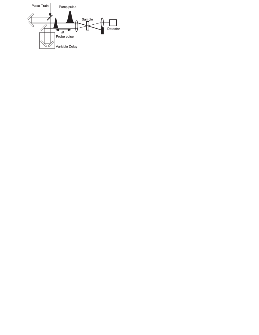
Femtosecond lasers have proven to be powerful tools for studying the dynamical behavior of photoexcited electrons and holes in semiconductors with a time resolution as short as a few femtoseconds. Here we review some results of our pump-probe measurements on coherent acoustic phonons in GaN heterostructures. Fig.1 shows a schematic diagram of the transient transmission measurement setup, which is usually referred to as a pump-probe setup. The output of the femtosecond laser is divided into two beams; one is used as the pump beam and the other, much weaker, beam is used as the probe. A mechanical delay stage introduces a time delay between these two synchronized pulse trains. The pump pulse photoexcites the semiconductor and modifies its optical properties, e.g., absorption. The excitation relaxes within a few tens of femtoseconds to several hundred picoseconds. By measuring the induced transmission change of the probe pulse as a function of time delay, we can study the time-resolved carrier dynamics of the photoexcited semiconductors.
We first discuss the basic mechanisms responsible for photoexcitation and detection of large amplitude coherent LA phonons in strained InGaN/GaN MQWs with built-in piezoelectric fields. The UV femtosecond pulse first photoexcited electrons and holes within the MQWs. These photogenerated carriers are spatially separated due to the strong built-in piezoelectric field. The photocarriers in turn screen the piezoelectric field and change the equilibrium state of the lattice through piezoelectric coupling. The lattice relaxes toward the new inhomogeneous configuration, and a displacive coherent phonon oscillation is thus initiated. The induced acoustic phonon oscillations result in piezoelectric field modulations, which cause variations in the absorption through the quantum confined Franz-Keldysh (QCFK) effect Miller86 . After photoexcitation, the observed probe transmission changes decay with time as the propagating acoustic phonons leave the MQW, resulting in a decay time constant proportional to the total number of wells. It is important to note that the decay of the transmission is related to the phonons leaving the MQW and not the actual decay of the phonon modes.
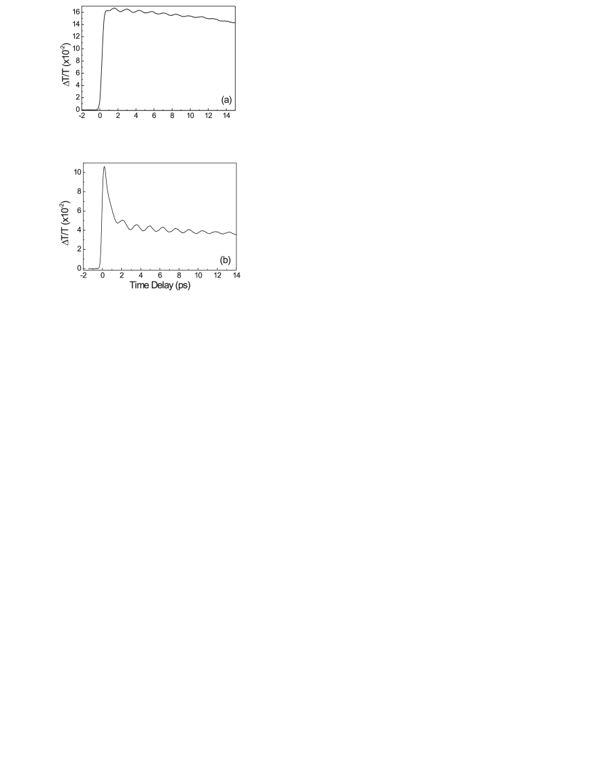
Fig.2 shows the measured probe transmission changes as a function of probe delay for a 14-period 50 Å/43 Å InGaN/GaN MQW sample at wavelengths of 390 nm (3.177 eV) and 365 nm (3.39 eV). The average incident pump power was 20 mW. And the average 2D/3D photocarrier densities were cm-2/ cm-3 and cm-2/ cm-3 for the 390 and 365 nm traces, respectively. After the pump excited carriers and caused a large transient transmission increases at zero time delay, a cosine-like transmission oscillation could be observed on top of the carrier cooling background signal. The amplitude of the cosine-like transmission modulation, , was on the order of 10-2. Within our experimental resolution, the observed oscillation frequency was found to be independent of the pump/probe photoenergy or pump fluence. The transmission oscillations can be fit using cosine functions with phases of zero or , which suggests that the oscillations are displacive in nature Cheng91 . The observed cosine-like oscillation is consistent with the picture that a new equilibrium configuration for the lattice system is set up by photo carrier screening of the strain-induced piezoelectric field. We shall discuss the generation mechanism and the displacive property of coherent acoustic phonons in more detail in the following sections.
III Microscopic theory of coherent acoustic phonons
Recently, Sanders et al. presented a microscopic theory for the generation and propagation of coherent LA phonons in strained InGaN/GaN MQWs Sanders01 . The authors used a density matrix formalism to treat the photoexcited electronic system and coherent acoustic phonons. And it was found that under typical experimental conditions, the microscopic theory can be simplified and mapped onto a loaded-string problem that can be easily solved. Here we review some important results of the microscopic theory for comparison with the macroscopic approach.
The heterostructure is assumed to have a cylindrical symmetry along the crystal c-axis which is along the axis, i.e. the (0001) direction. Thus the quantized state of electrons has a localized wavefunction along the axis due to quantum confinement of the heterostructure, while in the plane, the electrons are free to move. For simplicity, we also neglect the discontinuities of the elastic constants within the heterostructure as a first order approximation. The phonon eigenstates are just bulklike plane-waves. Due to the cylindrical symmetry, only acoustic phonons are coupled by the electron-phonon interaction. The free LA phonon Hamiltonian can be written as
| (1) |
where and are creation and annihilation operators for LA phonons with wave vector . The phonon dispersion relation is simply , where is the LA phonon sound velocity for propagation parallel to .
The interaction Hamiltonian for LA phonon and electrons is
| (2) |
where and are the creation and annihilation operators for electrons. The index refers to conduction or valence subbands, and are the subband indices. is the in-plane wave vector for electrons in the subbands. The interaction matrix elements describing deformation potential and piezoelectric scattering are
| (3) |
where is the crystal volume and is the density. The first term in Eq.(III) describes deformation potential scattering while the second term describes screened piezoelectric scattering. The factors and are related to the electron confinement wavefunctions along the axis.
In order to apply the generalized density matrix formalism, one define the electron density matrix
| (4) |
where denotes the quantum and statistical average of the nonequilibrium state of the system. The interband components of the density matrix, and , describe the coherence between conduction and valence electrons in subbands and and are related to the optical polarization. The intraband components of the density matrix describe correlations between different subbands of the same carrier type if . If , is just the carrier distribution function for electrons in the subband state.
The coherent phonon amplitude of mode is defined to be Kuznetsov94
| (5) |
The coherent phonon amplitude is related to the macroscopic lattice displacement through the relations
| (6) |
The equation of motion for these statistical operators can be obtained using the Heisenberg equation: The electrons also couple to the laser field through dipole interaction. The coherent phonon amplitudes satisfy the driven harmonic oscillator equations
| (7) |
subject to the initial conditions: . The equations of motion for coherent LA phonons are coupled to the electronic intraband polarization whose dynamical equations can also be derived from the Heisenberg equation. Based on a linear dispersion relation for LA phonons, one can transform the above dynamic equation for into a loaded string equation for
| (8) |
with the following source function
| (9) |
The initial conditions for are: . In the following section, we shall derive the same loaded string equation from a macroscopic approach with a simplified source function.
IV Macroscopic continuum theory for general crystal orientations
In this section, we develop a continuum elastic model for the generation of coherent acoustic waves in nitride-based nanostructures. The model is based on the macroscopic constituitive equations taking into account both the piezoelectric and deformation potential couplings. The governing dynamical equations are the elastic wave equations coupled to Poisson equation. This approach is valid in the coherent regime since thermal and quantum fluctuations can be neglected. More specifically, these equations can be regarded as the corresponding operator equations with appropriate quantum averages of the nonlinear terms. Here we consider coherent phonon generation in arbitrarily orientated MQWs. In order to consider the crystallographic effect, we use to denote the primary crystallographic axes of wurtzite nitrides. The direction is along the crystal -axis and is along the crystal growth direction. From the symmetry of wurtzite crystals, the macroscopic properties depend solely on the angle between and the -axis. Thus we may let . From the Miller-Bravais notation Mireles00 , , so that the polar angle can be expressed as a function of indices and only with . Here is the internal structure parameter, with and the usual hexagonal lattice parameters. We use to denote the coordinate along the growth direction.
The free energy density of a piezoelectric semiconductor is Royer00 ; Gusev93
| (10) |
where we have taken the temperature , electric field , and strain as independent thermodynamic variables. In the above expression, , , and are the isothermal elastic stiffness, dielectric, and piezoelectric tensors, respectively. The index runs over carrier species (electrons and holes), is the number density of carrier species , and is the corresponding deformation potential. Please note the convention that repeated indices imply summation is used throughout the text. The last two terms in Eq.(IV), represent piezoelectric and deformation potential couplings, respectively. From the free energy density, we can derive the stress tensor and electric displacement according to and , respectively. We obtain the following constitution equations for piezoelectric semiconductors
| (11) |
| (12) |
As discussed in the previous section, we neglect the elastic discontinuities here and regard the semiconductor heterostructure as a continuous medium. For InGaN/GaN heterostructures, this approximation is plausible since the elastic properites of InN is close to those of GaN. The macroscopic equation of motion is
| (13) |
where is the lattice displacement relative to the static equilibrium state in the absence of photoexcitation.
The electric displacement satisfies the Poisson equation
| (14) |
where is the space charge density. From the cylindrical symmetry of the carrier distribution which varies along the growth direction of the heterostructure, these dynamical variables are functions of the spatial variable only. In the quasi-static approximation, we assume the electric field is irrotational, . By substituting the constitution equation into dynamic and Poisson equations, we obtain
| (15) |
| (16) |
Here we have introduced the following effective constants along direction :
| (17) | |||||
| (18) | |||||
| (19) | |||||
| (20) |
is the Christoffel tensor, is the effective dielectric constant, is the effective piezoelectric tensor, and is the effective deformation potential coefficient for species . Note that no summation over index is assumed in Eq.(20). By eliminating the electric field, we obtain the following loaded wave equation
| (21) |
where is the effective Christoffel tensor. The two driving forces are
| (22) |
| (23) |
is the driving force due to piezoelectric coupling and is caused by deformation potential. From Eq.(22), the piezoelectric force is proportional to the space charge density and is parallel to the effective piezoelectric constant . On the other hand, the deformation potential force is proportional to the spatial derivative of the carrier density and is parallel to the effective deformation potential coefficient for each carrier species . Since the deformation potential constants are approximately the same for different directions , it can be seen from Eq.(20) and (23) that the deformation potential force approximately points to the crystal growth direction .
To solve the loaded wave equation (21), we first find the eigenmodes of the Christoffel tensor. The coherent acoustic waves are then expressed as superpositions of these eigenmodes. The driving forces for each eigenmode are then obtained by projecting the general forces onto the directions of the eigenmodes. The eigenmodes are obtained by solving the Christoffel equation
| (24) |
where is the phase velocity of the eigenmode and is the corresponding polarization of the lattice displacement. The Christoffel equation is an eigenvalue equation with being the eigenvalue and the eigen-polarization. correspond to the three eigenmodes. The general solution of the acoustic field is . And the mode amplitudes satisfy the following loaded string equation
| (25) |
One of the eigen-polarizations is always perpendicular to the plane spanned by -axis and the growth direction . This mode is an exact transverse mode. However, it will not be excited since the projection of the driving forces on this direction vanishes. The other two eigenmodes are in the plane spaned by and . Their polarizations are quasi-transverse and quasi-longitudinal. For orientation along [0001], these two modes are exact longitudinal acoustic (LA) and transverse acoustic (TA) phonons.
V Loaded string equation and detection of coherent acoustic phonons
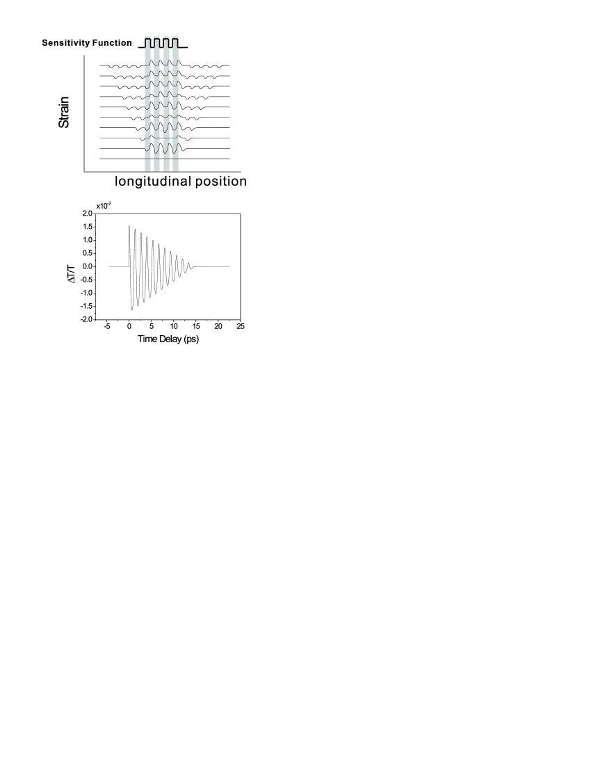
The loaded string equation can be solved by Green’s function method as discussed in Ref.Sanders01, . Here we solved the loaded string equation for the case of a InGaN/GaN MQW with 4 wells. The In composition is 10% and the well and barrier widths are Å and Å,respectively. In Fig.3 we show the time evolution (from the bottom trace to the top trace) of the coherent phonon strain field. The strain field is The results shown in Fig.3 correspond to strain distribution at time delays , where and is the fundamental oscillation period. After the acoustic wave trains leave the MQW region, a static carrier-induced strain exists in the MQW.
The transmission changes of the probe pulse due to the existence of coherent acoustic phonons can be described using a sensitivity function Stanton02 ; Thomsen86 . The differential transmission due to the time-varying strain field can be written as
| (26) |
is called the sensitivity function. A schematic sensitivity function is shown in Fig.3. Here for simplicity, we assume a binary form of the sensitivity function. As the photoexcited acoustic waves propagate outward, its strain field overlaps with the sensitivity function periodically with a time constant equal to the oscillation period. This periodic overlapping results in the observed oscillations of the probe differential transmissions. Also shown in Fig.3 (the lower part) is the calculated probe transmission change using the sensitivity function and strain fields shown on left of the figure. The result agrees well with the experimentally measured traces.
VI Crystal orientation effect
Here we apply the macroscopic approach developed in Section 4 to investigate coherent phonon generation in nitride-based MQWs with arbitrary growth directions. The current crystal-growth technique has made it possible to grow wurtzite nitrides along orientations other than the conventional -axis. Optical and electrical experimental studies also reveal many special properties of GaN with different crystal orientations Lei93 ; Alemu98 . Theoretical studies of crystal orientation effects on wurtzite semiconductor band structures have been reported by many authors, e.g. Ref.Mireles00, . We will show in the following that, for MQWs with certain orientation angles, coherent transverse acoustic (TA) phonons will be excited and dominate the coherent LA phonon signals. This THz shear acoustic wave might have special applications for picosecond ultrasonics.
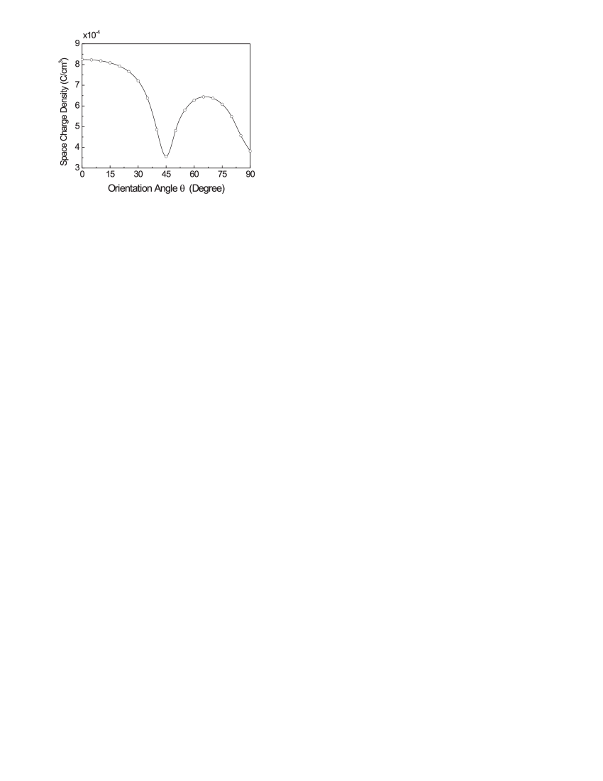
As discussed previously, the photogenerated space charge density is important for the generation of coherent phonons. Here we first investigate the orientation effects on the space charges. The crystal orientation effects on the subband structure of strained wurtzite multiple quantum wells can be found in Ref.Mireles00, . In the following calculation, the In composition is , the well width is 22Å, and the barrier width is 90 Å. As discussed in the preceding section, the piezoelectric coupling dominates the driving force. The piezoelectric coupling is due to the space-charge field created by separation of photogenerated electrons and holes, i.e. it depends on the magnitude of the space charge density . In Fig.4 we show the magnitude of the corresponding fundamental Fourier component versus the orientation angle . The photoexcited 2D carrier density is fixed at cm-2. The magnitude of has minima at and . This is because the built-in piezoelectric field vanishes at these angles. The maximum magnitude of the space charge density is at , which is the conventional [0001] orientation, and a second local maximum occurs at .
After photogeneration the coherent acoustic waves leave the MQW region within a finite time interval, and a static carrier-induced strain field remains inside the MQW. In the following, we shall mainly consider the radiating component. We define the strain field associated with mode as
| (27) |
Since the driving forces on the right hand side of Eq.(25) satisfy the sum rule , the strain field has a well-defined Fourier transform, which obeys the following driven harmonic oscillator equation
| (28) |
where and are the Fourier transform functions of the strain field and force . The oscillating frequency . Due to the periodic carrier distribution within the MQW, the Fourier transform of the driving force has peaks at , where is an integer and . The finite linewidth of each peak is due to the finite number of wells and the inhomogeneous distribution of photogenerated carriers. This finite linewidth corresponds to the observed decay time constant of oscillating traces. The solution to the above oscillator equation can be expressed as a superposition of displacive cosinusoidal oscillations
| (29) |
The time derivative is proportional to the carrier generation rate, which is in turn approximately proportional to the pulse shape. Let be the normalized pulse shape function, i.e. , and be its Fourier transform. The solution (29) can be approximated as
| (30) |
| (31) |
Where and is the pulse width. There are two terms on the right-hand side of Eq.(30). The first term, , corresponds to the static carrier-induced strain field Sanders01 . This steady state field can be obtained by solving the following equation
| (32) |
The second term on the right-hand side of Eq.(30) corresponds to the radiating part of the strain field, i.e. the observed coherent phonon oscillations. The magnitude of the coherent acoustic wave is proportional to the steady-state component , and is reduced by the pulse factor . In the following, we shall investigate the orientation effect on the magnitude of the first-order harmonic component, i.e. .
As discussed in Section 4, only two acoustic modes will be excited by the photogenerated carriers. The two modes are quasi-LA and quasi-TA modes. We shall simply refer to them as LA and TA modes. The total acoustic field can thus be expressed as
| (33) |
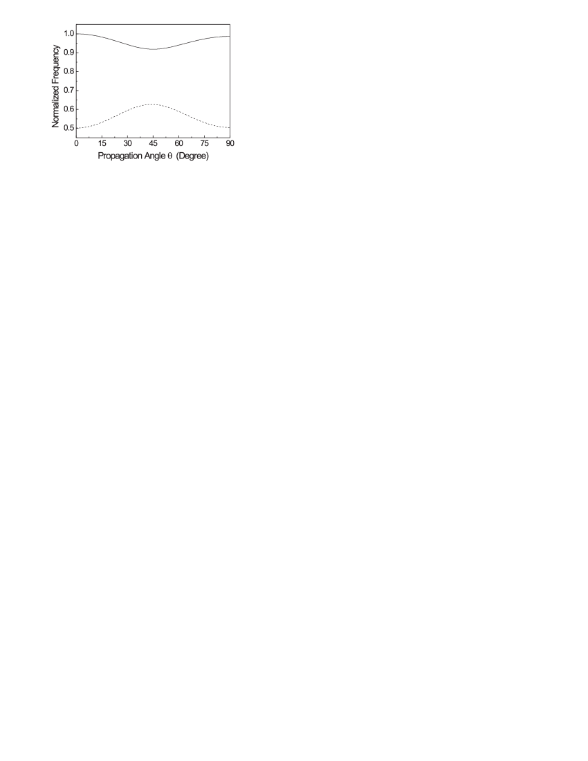
Where and are the mode amplitudes of the LA and TA phonons, respectively. We shall first compare their modal properties versus propagation directions. The fundamental oscillation frequencies of the two modes are and , respectively. In Fig.5, we show the crystal-orientation dependence of the normalized oscillating frequencies for both the LA (solid line) and TA (dotted line) modes. The normalization was made relative to the oscillation frequency of an LA mode along the [0001] direction with a fixed wavevector . The oscillation frequency of the TA mode is approximately half that of the LA mode. Both frequencies are symmetric with respect to , while the frequency of the LA (TA) mode has a minimum (maximum) at this orientation angle. Since both oscillating modes will contribute to the absorption modulaton through piezoelectric field or deformation potential coupling, a beating phenomenon will be observed in the time-resolved pump-probe measurements. However, the amplitude of the beating depends also on the relative magnitudes of the LA and TA modes, as we shall discuss later.
We now introduce the effective piezoelectric and deformation potential coupling coefficients for the two eigenmodes. The effective coupling coefficients appear in the driving force equations (=LA, or TA) as
| (34) |
| (35) |
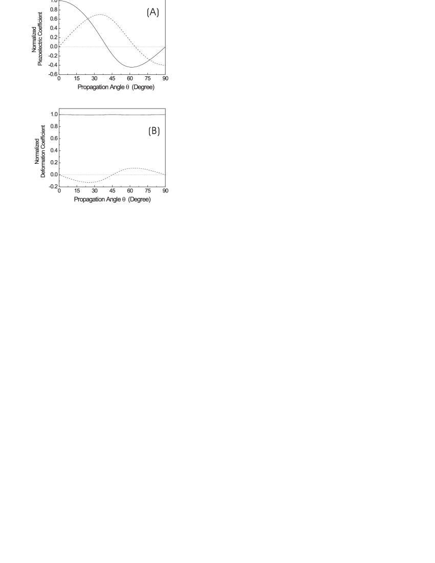
Fig.6(A) shows the orientation dependence of the normalized effective piezoelectric coefficients and for the coherent LA (solid line) and TA (dotted line) modes, respectively. The normalization was made with respect to . The effective LA mode coupling constant, , has a maximum at , i.e. the [0001] direction, and nodes at and . Thus the magnitude of the coherent LA phonon oscillations is expected to be small at these node angles. As for the TA mode, has nodes at and . Since the deformation potential driving force for TA modes is very small for all orientation angles, the TA mode cannot be excited in the conventional [0001] direction due to . However, it is expected that in the [100] direction, i.e. , the generation of the TA mode will dominate over that of the LA mode. In Fig.6(B), we show the normalized effective coefficients for electron deformation coupling, and , as functions of the propagation angles. The normalization was again made with respect to the of the LA mode in the [0001] direction. As discussed previously, the deformation coefficient is approximately proportional to the projection of the propagation unit vector on the mode polarization vector . It can be seen from Fig.6(B) that the normalized coefficient of the LA mode is almost equal to 1 for all orientations, while that of the TA modes is almost zero.
Now we shall investigate the orientation dependence of the driving forces for the LA and TA modes. We consider a MQW with 10% In composition, a well width Å, and a barrier width Å. We assume a constant 2D photogenerated carrier density of cm-2 for all orientations. We can thus compare the intrinsic effects of crystal orientation on the generation of acoustic phonons. Please note that the optical absorption properties depend on the orientation, one needs different pump intensities to achieve the same carrier density at different orientation angles. The orientation dependence of the photogenerated carrier densities and space charge density corresponding to the same MQW parameters are discussed above, e.g. Fig.4 for the space charge density. Those results combined with the effective coefficients are now used to derive the driving forces for each mode. In Fig.7(A), we first show the magnitude of the driving forces versus orientation angle for the LA mode. Here we only show the Fourier component corresponding to the fundamental wavevector . As can be seen from the figure, the piezoelectric force dominates the generation of coherent phonons and the deformation potential coupling force is almost independent on the orientation angles. From Eq.(34), the piezoelectric driving force is proportional to the effective piezoelectric coefficient and the space charge density. The magnitude of the space charge component has a minimum near [See Fig.4] and the effective LA mode piezoelectric coefficient has nodes at both and [see Fig.6(A)]. As a result, the piezoelectric force for the LA mode vanishes at both orientation angles. However, contrary to the case of the TA modes (discussed below), the LA mode has a constant contribution from deformation potential coupling for all orientation angles.
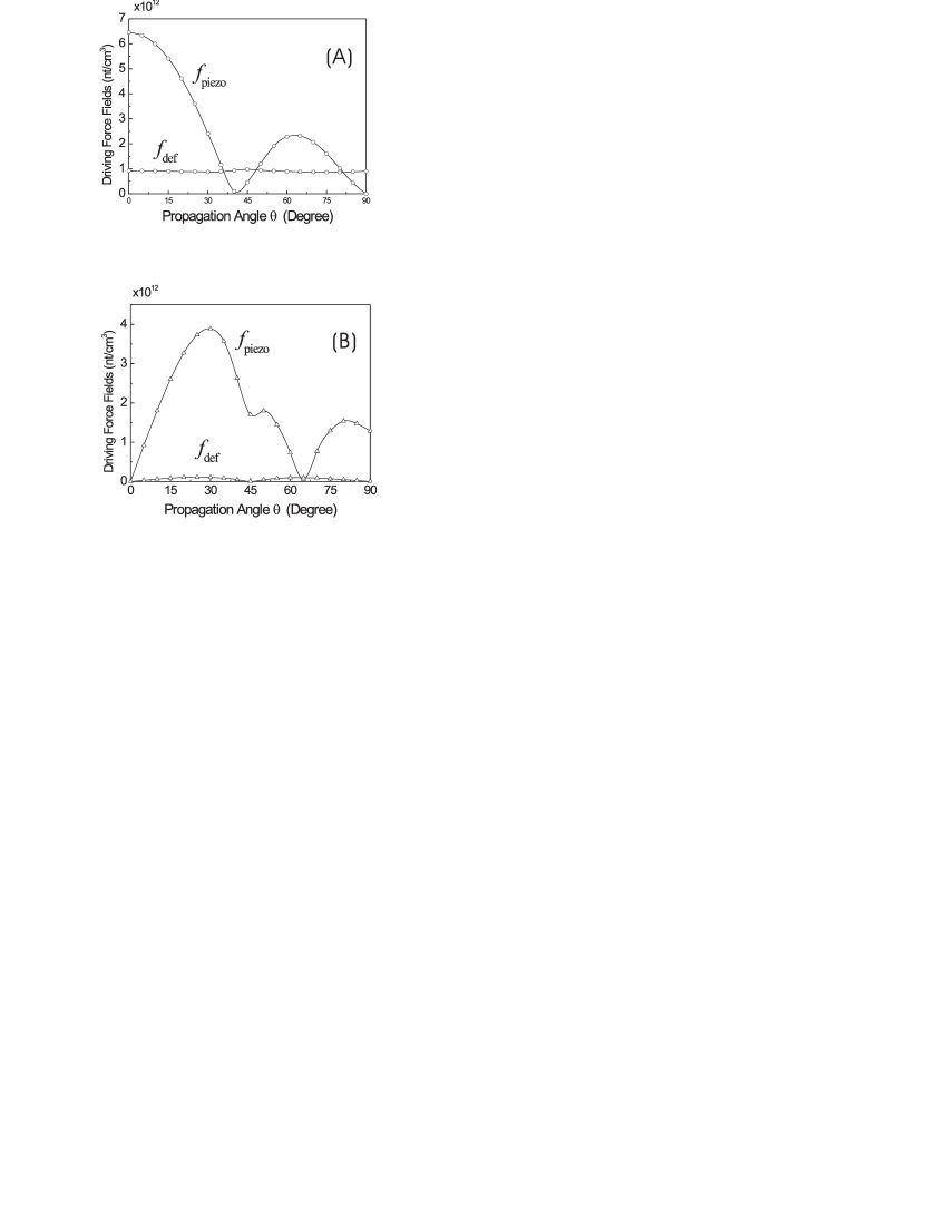
Fig.7(B) shows the magnitudes of the driving forces versus orientation angles for the TA mode. The deformation coupling force is very small compared to the piezoelectric force and the piezoelectric force vanishes at angles corresponding to the nodes of the effective TA piezoelectric coefficient. A kink-like minimum at in the magnitude of the piezoelectric force is due to a minimum in the space charge component. The piezoelectric force is largest at angles .
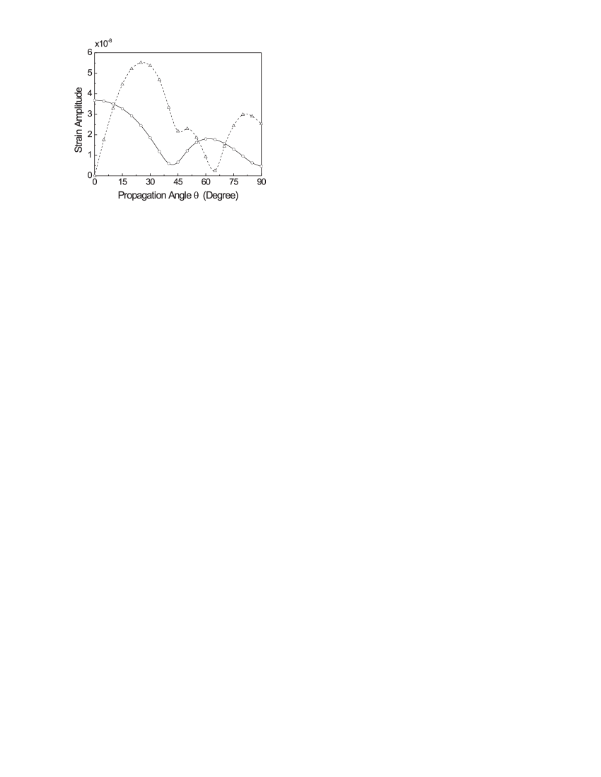
Finally, in Fig.8 we show the resultant strain amplitudes of both modes versus the orientation angles. It can be seen that although only the LA mode is present in the [0001] direction, for other orientations both LA and TA modes will be excited. The generation of the TA mode even dominates over that of the LA mode for certain orientation angles, especially at and (the [100] direction). In addition to the well-known LA acoustic wave generated along [0001] direction, our results suggest that shear acoustic waves can be excited in wurtzite semiconductor MQW’s with suitably chosen crystal orientations. For example, TA-dominant acoustic waves can be generated by photoexciting a (100)-grown MQW. These findings may have potential applications in picosecond ultrasonics.
VII Conclusion
In this paper we have provided an introductory review of the experimental and theoretical aspects of coherent acoustic phonon generation in nitride-based semiconductor heterostructures, with particular application to InGaN/GaN MQWs.
We first presented the observation of coherent LA phonon oscillations in InGaN/GaN MQWs from transmission-type pump-probe measurements. With UV femtosecond pulse excitation, the large built-in piezoelectric field in the InGaN well region spatially separates the photogenerated electrons and holes. This separation causes a space charge density that partially screens the original electric field in the MQW. Due to piezoelectric coupling, the corresponding equilibrium lattice state is shifted and a displacive coherent LA phonon oscillation is then initiated. The photogenerated carrier distribution is confined within the well region and is a periodic function with wave vector , where and are the well and barrier widths, respectively. Coherent phonon oscillation, with the selected acoustic phonon mode corresponding to the wave vector , can then be initiated. The phonon has an oscillation frequency . The induced acoustic phonon oscillation results in piezoelectric field modulation and then causes absorption variation through the quantum confined Franz-Keldysh effect. The observed decay time constant of the measured trace indicates the time required for the generated coherent phonons to leave the MQW region.
We also reviewed the recently proposed microscopic theory for the generation and propagation of coherent LA phonons in wurtzite semiconductor MQW’s. The coherent acoustic phonon oscillation is a macroscopic coherent population of the phonon states. In this respect, it is similar to a laser photon field, which is a macroscopic coherent state of photons. Motivated by applications to more complicated coherent acoustic devices, we developed a macroscopic theory for the generation and dynamics of coherent acoustic phonons in wurtzite MQW’s. The approach is based on macroscopic continuum constitution equations for piezoelectric wurtzite semiconductors. Starting from Poisson equation and the dynamic elastic equation, a vector loaded wave equation was obtained. By projecting the corresponding equation to eigenvectors of the elastic Christoffel equation, the loaded string equation is derived. Only two acoustic eigenmodes can be excited by photogeneration. They are the quasi-longitudinal and quasi-transverse modes. We also applied the macroscopic approach to study crystal-orientation effects on the generation of coherent acoustic phonons. It is found that although only the LA phonon is photoexcited as the crystal is grown along the [0001] direction, at other orientations, e.g. [100], the generation of TA phonon is favored. This coherent transverse wave may have potential applications in THz ultrasonics.
Acknowledgements.
The InGaN MQW sample was kindly provided by S. P. DenBaars. The authors would like to acknowledge stimulating scientific discussions with C. J. Stanton and G. D. Sanders. This work is sponsored by National Science Council of Taiwan, R.O.C. under Grant No. 91-2112-M-002-050 and NSC91-2215-E-002-021..References
- (1) J. Shah, Ultrafast Spectroscopy of Semiconductors and Semiconductor Nanostructures, Springer, Berlin, 1999.
- (2) P. C. Becker, H. L. Fragnito, C. H. Brito Cruz, J. Shah, R. L. Fork, J. E. Cunningham, J. E. Henry, and C. V. Shank, Appl. Phys. Lett., 53, pp. 2089, 1988.
- (3) W. H. Knox, C. Hirlimann, D. A. B. Miller, J. Shah, D. S. Chemla, and C. V. Shank, Phys. Rev. Lett., 56, pp. 1191, 1986.
- (4) D. S. Kim, J. Shah, T. C. Damen, W. Schäfer, F. Jahnke, S. Schmitt-Rink, and K. Köhler, Phys. Rev. Lett., 69, pp. 2725, 1992.
- (5) J. Shah, Spectroscopy of Nonequilibrium Electrons and Phonons, ed. by C. V. Shank, B. P. Zakharchenya, Elsevier, Amsterdam, pp. 57–112, 1992.
- (6) P. Leisching, P. H. Bolivar, W. Beck, Y. Dhaibi, F. Brüggerman, R. Schwendler, H. Kurz, K. Leo, and K.Köhler, Phys. Rev. B, 50, pp. 14389, 1994.
- (7) T. Dekorsey, R. Ott, H. Kurz, and K. Köhler, Phys. Rev. B, 51, pp. 17275, 1995.
- (8) K. Leo, T. C. Damen, J. Shah, E. O. Göbel, and K. Köhler, Appl. Phys. Lett., 57, pp. 19, 1990.
- (9) S. T. Cundiff, A. Knorr, J. Feldmann, S. W. Koch, E. O. Göbel, and H. Nickel, Phys. Rev. Lett., 73, pp. 1178, 1994.
- (10) J. Feldmann, M. Koch, E. O. Göbel, F. Jahnke, T. Meier, W. Schäfer, P. Thomas, S. W. Koch, H. Nickel, S. Luttgen, and W. Stölz, Semicond. Sci. Technol., 9, pp. 1965, 1994.
- (11) K. Leo, J. Shah, E. O. Göbel, T. C. Damen, S. Schmitt-Rink, W. Schäfer, and K. Köhler, Phys. Rev. Lett., 66, pp. 201, 1991.
- (12) H. G. Roskos, M. C. Nuss, J. Shah, K. Leo, D. A. B. Miller, A. M. Fox, S. Schmitt-Rink, and K. Köhler, Phys. Rev. Lett., 68, pp. 2216, 1992.
- (13) A. Bonvalet, J. Nagle, V. Berger, A. Migus, J.-L. Martin, and M. Joffe, Phys. Rev. Lett., 76, pp. 4392, 1996.
- (14) A. V. Kuznetsov and C. J. Stanton, Phys. Rev. Lett., 73, pp. 3243, 1994.
- (15) G. C. Cho, W. Kutt, and H. Kurz, Phys. Rev. Lett., 65, pp. 764, 1990.
- (16) T. Pfeifer, W. Kutt, H. Kurz, and H. Schölz, Phys. Rev. Lett., 69, pp. 3248, 1992.
- (17) T. K. Cheng, J. Vidal, H. J. Zeiger, G. Dresselhaus, M. S. Dresselhaus, and E. P. Ippen, Appl. Phys. Lett., 59, pp. 1923, 1991.
- (18) W. Albrecht, Th. Kruse, and H. Kurz, Phys. Rev. Lett., 69, pp. 1451, 1992.
- (19) For a review, see W. A. Kutt, W. Albrecht, and H. Kurz, IEEE J. Quantum Electron., 28, pp. 2434, 1992.
- (20) K. A. Nelson, D. R. Lutz, M. D. Fayer, and L. Madison, Phys. Rev. B, 24, pp. 3261, 1981.
- (21) C. Thomsen, H. T. Grahn, H. J. Maris, and J. Tauc, Phys. Rev. B, 34, pp. 4129, 1986.
- (22) A. Yamamoto, T. Mishina, Y. Masumoto, and M. Nakayama, Phys. Rev. Lett., 73, pp. 740, 1994.
- (23) A. Bartels, T. Dekorsey, H. Kurz, and K. Köhler, Phys. Rev. Lett., 82, pp. 1044, 1999.
- (24) T. D. Krauss and F. W. Wise, Phys. Rev. Lett., 79, pp. 5102, 1997.
- (25) M. Nisoli, S. De Silvestri, A. Cavalleri, A. M. Malvezzi, A. Stella, G. Lanzani, P. Cheyssac, and R. Kofman, Phys. Rev. B, 55, pp. R13424, 1997.
- (26) C.-K. Sun, J.-C. Liang, and X.-Y. Yu, Phys. Rev. Lett., 84, pp. 179, 2000.
- (27) C.-K. Sun, Y.-K. Huang, J.-C. Liang, A. Abare and S. P. DenBaars, Appl. Phys. Lett., 78, pp. 1201, 2001.
- (28) Ü. Özgür, C.-W. Lee, and H. O. Everitt, Phys. Rev. Lett., 86, pp. 5604, 2001.
- (29) D. A. B. Miller, D. S. Chemla, and S. Schmit-Rink, Phys. Rev. B, 33, pp. 6976, 1986.
- (30) G. D. Sanders, C. J. Stanton, and C. S. Kim, Phys. Rev. B, 64, 235316, 2001.
- (31) F. Mireles and S. E. Ulloa, Phys. Rev. B, 62, pp. 2562, 2000.
- (32) D. Royer and E. Dieulesaint, Elastic Waves in Solids, Springer, Berlin, 2000.
- (33) V. E. Gusev and A. A. Karabutov, Laser Optoacoustics, American Institute of Physics, New York, 1993.
- (34) C. J. Stanton, G. D. Sanders, R. L. Liu, C. S. Kim, J. S. Yahng, E. Oh, D. S. Kim, and C.-K. Sun, in Ultrafast Phenomena in Semiconductors VI, K.-T. F. Tsen, J. J. Song, and H. Jiang, ed., Proc. SPIE 4643, pp. 124, 2002.
- (35) T. Lei, K. F. Ludwig Jr., and T. D. Moustakas, J. Appl. Phys., 74, pp. 4430, 1993.
- (36) A. Alemu, B. Gil, M. Julier, and S. Nakamura, Phys. Rev. B, 57, pp. 3761, 1998.