Mean-field model for the interference of matter waves from a three-dimensional optical trap
Abstract
Using the mean-field time-dependent Gross-Pitaevskii equation we study the formation of a repulsive Bose-Einstein condensate on a combined optical and harmonic traps in two and three dimensions and subsequent generation of the interference pattern upon the removal of the combined traps as in the experiment by Greiner et al. [Nature (London) 415, 39 (2002)]. For optical traps of moderate strength, interference pattern of 27 (9) prominent bright spots is found to be formed in three (two) dimensions on a cubic (square) lattice in agreement with experiment. Similar interference pattern can also be formed upon removal of the optical lattice trap only. The pattern so formed can oscillate for a long time in the harmonic trap which can be observed experimentally.
keywords:
Bose-Einstein condensation, Interference of matter wavePACS:
03.75.-b, 03.75.Lm, 03.75.KkThe recent experimental observation of trapped Bose-Einstein condensates (BECs) in alkali-metal atoms [1] has offered new possibility for the realization of matter-wave interference in the laboratory [2]. The major breakthrough in this endeavor has come from the formation of harmonically trapped BEC on optical-lattice periodic potential in one [3, 4] and three [5, 6] dimensions which has permitted the study of quantum phase effects on a macroscopic scale such as interference of matter waves. Innovative interesting experiments on interference of matter waves from different optical lattice centers have been performed. The phase coherence between different sites of a trapped BEC on an optical lattice has been established in two recent experiments [3, 4] through the formation of distinct interference pattern when the traps are removed.
Among these experiments on BEC in optical lattice potential, the one worth mentioning is the observation by Cataliotti et al. [7] of a robust pattern in the form of three bright spots generated via the interference of matter waves coming from different optical lattice centers in one dimension after the removal of the traps. The recent three-dimensional extension of this experiment by Greiner et al. [5] is a landmark of all such attempts [6]. The observation of a sharp interference pattern of 27 prominent bright spots arranged on a cubic lattice in that experiment upon removal of the combined traps from a BEC formed in three-dimensional optical and harmonic traps is a clear manifestation of phase coherence over the initial condensate. There have been several theoretical studies on different aspects of a BEC in a optical lattice potential [8].
In the recent experiment, Greiner et al. [5] provided quantitative measurement of the formation and evolution of interference pattern upon free expansion of a harmonically trapped BEC of repulsive 87Rb atoms formed on an optical lattice potential after removing both traps. They also continued their investigation by increasing gradually the strength of the optical lattice potential using a standing-wave laser beam of increased intensity and found that the phase coherence between different sites is lost. Consequently, the interference pattern is destroyed for stronger optical lattice potential. This phenomenon is termed [5] the superfluid to Mott insulator transition. The superfluid state is the one with phase coherence at different optical lattice sites and the insulator state is the one where the phase coherence is destroyed by a strong optical lattice potential. In the superfluid phase atoms can move from one optical lattice site to another by quantum tunneling, whereas in the Mott insulator phase this tunneling is stopped. The motion of atoms in the two phases are similar to that of electrons in semi-conductors and insulators and hence the name Mott insulator to one of the phases. In this Letter we investigate how well the superfluid state on the three-dimensional optical lattice as well as the formation of the prominent interference pattern upon free expansion can be described by the mean-field nonlinear time-dependent Gross-Pitaevskii (GP) equation [9].
The time-dependent BEC wave function at position and time is described by the following mean-field nonlinear GP equation [9]
| (1) |
where is the mass and the number of atoms in the condensate, the strength of interatomic interaction with the atomic scattering length. The combined three-dimensional harmonic and optical lattice traps are given by where with , where is the angular frequency of the harmonic trap and is the optical lattice trap introduced later. The normalization condition is
In three dimensions, the wave function can be written as . Now transforming to dimensionless variables , , , , and Eq. (1) becomes [10]
| (2) | |||||
with nonlinearity and normalization
| (3) |
The optical potential created with the standing-wave laser field of wavelength is given by , with , , and the dimensionless strength of the optical potential [5]. The present dimensionless length unit is and time unit is . In a typical experiment m and ms. In terms of the dimensionless laser wave length and the dimensionless standing-wave energy parameter , is given by
| (4) |
In the experiment of Greiner et al. [5] with repulsive 87Rb atoms in the hyperfine state , Hz, nm, kg, m, ms and . In that experiment 65 lattice sites in the single direction are populated in the initial state by a total number of more than 500 000 atoms. Because of limitations in computer processing time and memory we present here a model calculation with a smaller condensate.
We solve Eq. (2) numerically using a split-step (four-step) time-iteration method with the Crank-Nicholson discretization scheme described recently [11]. The three kinetic energy derivative terms were treated in three separate steps. All nonderivative terms are treated in the fourth step. To calculate the initial state on optical lattice we discretize the GP equation spanning from to 5, . The time iteration is started with the known harmonic oscillator solution of Eq. (2) for . For a typical condensate the chemical potential is much smaller than the typical strength of the optical potential wells , so that passage of condensate atoms from one well to other can only proceed through quantum tunneling. The nonlinearity as well as the optical lattice potential parameter are slowly increased by equal amounts in steps of time iteration until the desired value of nonlinearity and optical lattice potentials are attained. Then, without changing any parameter, the solution so obtained is iterated several thousand times so that a stable solution is obtained independent of the initial input and time and space steps. The solution then corresponds to the bound BEC under the joint action of the harmonic and optical traps. To study the expansion of the condensate upon the removal of the traps the initial wave function is loaded at the center of a bigger lattice defined by The numerical calculation was performed with nonlinearity , and , although the general trend of the results presented in this Letter is independent of this particular choice.
However, we begin our study with a simpler model in two dimensions governed by the following dimensionless GP equation
| (5) |
with nonlinearity and normalization The sumation in the optical potential (4) in this case is limited to two terms only. Although, the results of this study in two dimensions cannot be directly compared with experiment, this serves as an excellent illustration of the physics involved in terms of this simpler model which makes the computation easier.
In two dimensions the wave function of the initial condensate was calculated by solving Eq. (5) using a split-step (three-step) time iteration method with the Crank-Nicholson scheme [11] on a lattice spanning from to 10. The kinetic energy derivative terms in two directions are treated in two different steps and all other nonderivative terms are treated in the third step. The expansion of the condensate was studied by loading the initial wave function on a larger lattice spanning from to 50. In the numerical calculation we used , , in Eq. (5).

The projection of the initial wave function on the plane (contour plot) in two dimensions is exhibited in Fig. 1. The bright positions are the maxima of the wave function and the dark regions represent minima. This figure clearly shows the formation of bright structures in the plane in the different optical potential wells. About 16 lattice sites are populated in a single direction in the initial state.
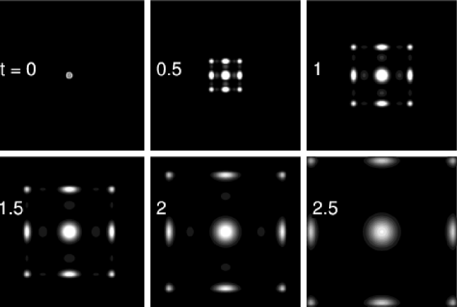
We next load the initial BEC of Fig. 1 at the center of a larger mat (area ) and remove both the harmonic and the optical lattice traps. The contour plot of the time evolution of the condensate is shown in Fig. 2. The initial wave function at is the same as the one in Fig. 1. However, the optical lattice pattern at is not visible in Fig. 2 because of the (large) size of the mat in this plot. When the condensate is released from the combined traps, a matter-wave interference pattern is formed in 0.25 time units. The atom cloud released from one lattice site expands, overlaps and interferes with atom clouds from neighboring sites to form the robust interference pattern due to phase coherence. No interference pattern can be formed without phase coherence. The interference pattern is composed of 9 prominent bright spots arranged on a square lattice with 4 spots at corners, 4 at the middle points of the sides and 1 at the center of the square. However, there are some weaker secondary spots in the interference pattern. The interference pattern keeps on expanding at larger times as shown in Fig. 2. Similar interference pattern was observed [7] also in one dimension, where the pattern is composed of three bright spots on a line in the form of a central peak and two symmetrically spaced peaks, each containing about of total number of atoms, moving apart from the central peak with a constant velocity.
Usually a repulsive condensate without a confining trap should disparse quickly [12]. The robust interference pattern formed from a repulsive condensate with very little spreading is similar to bright solitons. True bright solitons can be formed in attractive BEC only and have been observed experimentally [13, 14]. The phase coherence between the components of BEC at a large number of sites of optical lattice is responsible for the generation of the interference pattern with very little spreading. Without the initial phase coherence a repulsive condensate in the absence of a trap will disappear in few units of time [12]. Each of the moving interference peaks are similar to atom laser [3, 15] which can be used in the scattering of two coherent BECs and other purposes.
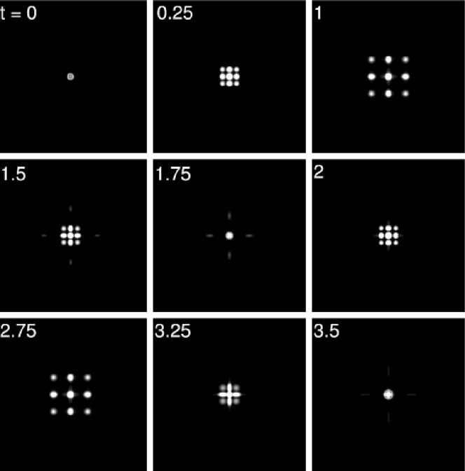
To study the robustness of the interference pattern we remove only the optical trap at time and allow the condensate to evolve in the harmonic trap alone so that the interference pattern cannot escape to infinity. In this case the interference pattern is formed quickly which tends to expand at small times. However, because of the confining harmonic trap, after some initial expansion the interference pattern starts to shrink towards the center. Eventually, it shrinks to a central spot and starts to expand again. This expansion and shrinking of the interference pattern without considerable distortion is repeated over many cycles of which we show the two first cycles in Fig. 3. The period of this oscillation is 3.5 units of time. The largest size of the interference pattern occurs approximately at and 2.75. This periodic oscillation of the interference pattern can be observed experimentally and the present mean-field prediction could be compared with future experiments.
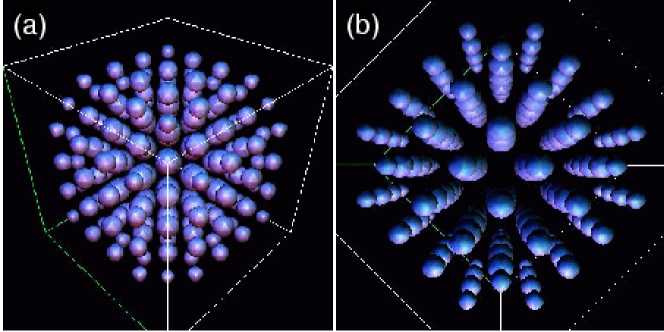
After this preliminary study in two dimensions we consider the formation of a BEC in a three-dimensional optical lattice trap and the subsequent formation of the interference pattern upon simultaneous removal of the optical lattice and harmonic traps. The initial solution for , and was calculated on a cube of size . In Fig. 4 we show the contour plot of the central part of the initial wave function on a cube of size . Two views of the three-dimensional pattern is shown. In Fig. 4 (a) we show the view in the diagonal direction and in Fig. 4 (b) we show that along one of the axes of the cube. The formation of the condensate in the three-dimensional cartesian lattice is clearly demonstrated in Fig. 4. About 8 to 10 lattice sites are populated in a single direction in the initial state of which the central portion is shown in Fig. 4.
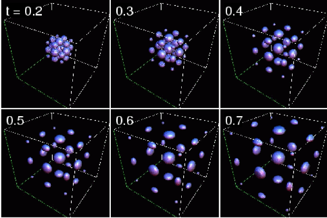
Next to study the formation and evolution of interference pattern in three dimensions we load the bound state of Fig. 4 at the center of a cube of size and remove the combined harmonic and optical lattice traps at . In Fig. 5 we show the time evolution of the condensate. Upon the removal of the traps a matter-wave interference pattern is formed quickly in less than 0.2 units of time. This pattern is composed of 27 prominent bright spots arranged on a cubic lattice: 8 at the corners, 12 at the middle points of the sides, 6 at the center of each of the bases, and 1 at the center of the cube. As in one and two dimensions, this pattern is also very robust and expands without considerable distortion as shown in Fig. 5. In both two and three dimensions the structure and the shape of the interference pattern is independent of the number of lattice sites occupied in the initial state, the nonlinearity , or the strength and the wave length of the optical trap potential.
In conclusion, to understand theoretically the experiment by Greiner et al. [7], we have studied in detail the phase coherence in a cubic condensate loaded in a combined harmonic and optical lattice traps using the solution of the full GP equation in three dimensions. We also performed a similar study on a two dimensional condensate. Using the split-step Crank-Nicholson method, first we obtain the initial wave function of the condensate in the combined harmonic and optical lattice traps. Then we study the time evolution of the system after the removal of both the traps. Robust interference patterns of 9 (in two dimensions) and 27 (in three dimensions) prominent bright spots are formed upon the removal of the traps. The present robust interference pattern for repulsive atoms with very little spreading is similar to bright solitons in case of attractive condensates. True bright solitons can be formed only in attractive BEC [13, 14]. The formation of the interference pattern clearly demonstrates the phase coherence in the initial condensate on the optical lattice. Each of the moving interference peaks formed of coherent matter wave is similar to a atom laser observed experimentally [3, 15]. The interference pattern can also be created by removing only the optical lattice trap. On removal of the optical lattice trap the interference pattern is found to oscillate in the harmonic trap without much distortion. This phenomenon demonstrates the robustness of the interference pattern and is studied in detail in two dimensions. This oscillation can be observed experimentally and the result of future experiments can be compared with the present mean-field prediction.
References
- [1] M. H. Anderson, J. R. Ensher, Jr., M. R. Matthews, C. E. Wieman, E. A. Cornell, Science 269 (1995) 198; J. R. Ensher, D. S. Jin, M. R. Matthews, C. E. Wieman, E. A. Cornell, Phys. Rev. Lett. 77 (1996) 4984; K. B. Davis, M. O. Mewes, M. R. Andrews, N. J. van Druten, D. S. Durfee, D. M. Kurn, W. Ketterle, Phys. Rev. Lett. 75 (1995) 3969; D. G. Fried, T. C. Killian, L. Willmann, D. Landhuis, S. C. Moss, D. Kleppner, T. J. Greytak, Phys. Rev. Lett. 81 (1998) 3811; C. C. Bradley, C. A. Sackett, J. J. Tollett, R. G. Hulet, Phys. Rev. Lett. 75 (1995) 1687;
- [2] M. R. Andrews, C. G. Townsend, H. J. Miesner, D. S. Durfee, D. M. Kurn, W. Ketterle, Science 275 (1997) 637.
- [3] B. P. Anderson, M. A. Kasevich, Science 282 (1998) 1686.
- [4] C. Orzel, A. K. Tuchman, M. L. Fenselau, M. Yasuda, M. A. Kasevich, Science 291 (2001) 2386.
- [5] M. Greiner, O. Mandel, T. Esslinger, T. W. Hansch, I. Bloch, Nature (London) 415 (2002) 39; M. Greiner, O. Mandel, T. W. Hansch, I. Bloch, Nature (London) 419 (2002) 51.
- [6] H. T. C. Stoof, Nature (London) 415 (2002) 25.
- [7] F. S. Cataliotti, S. Burger, C. Fort, P. Maddaloni, F. Minardi, A. Trombettoni, A. Smerzi, M. Inguscio, Science 293 (2001) 843.
- [8] Y. B. Band, M. Trippenbach, Phys. Rev. A 65 (2002) 053602; W. M. Liu, W. B. Fan, W. M. Zheng, J. Q. Liang, S T. Chui, Phys. Rev. Lett. 88 (2002) 170408; M. Kramer, L. Pitaevskii, S. Stringari, Phys. Rev. Lett. 88 (2002) 180404; K. Goral, L. Santos, M. Lewenstein, Phys. Rev. Lett. 88 (2002) 170406; A. A. Sukhorukov, Y. S. Kivshar, Phys. Rev. E 65 (2002) 036609; P. Massignan, M. Modugno, e-print cond-mat/0205516.
- [9] F. Dalfovo, S. Giorgini, L. P. Pitaevskii, S. Stringari, Rev. Mod. Phys. 71 (1999) 463.
- [10] S. K. Adhikari, Phys. Rev. E 65 (2002) 016703.
- [11] S. K. Adhikari, P. Muruganandam, J. Phys. B 35 (2002) 2831; S. K. Adhikari, P. Muruganandam, e-print cond-mat/0210177.
- [12] S. K. Adhikari, Phys. Rev. A 65 (2002) 033616; S. K. Adhikari, P. Muruganandam, Phys. Lett. A 301 (2002) 333.
- [13] K. E. Strecker, G. B. Partridge, A. G. Truscott, R. G. Hulet, Nature (London) 417 (2002) 150; L. Khaykovich, F. Schreck, G. Ferrari, T. Bourdel, J. Cubizolles, L. D. Carr, Y. Castin, C. Salomon, Science 296 (2002) 1290.
- [14] L. D. Carr, M. A. Leung, W. P. Reinhardt, J. Phys. B 33 (2000) 3983; V. M. Pérez-García, H. Michinel, H. Herrero, Phys. Rev. A 57 (1998) 3837; L. Salasnich, A. Parola, L. Reatto, Phys. Rev. A 66 (2002) 043603; A. E. Muryshev, H. B. van Linden van den Heuvell, G. V. Shlayapnikov, Phys. Rev. A 60 (1999) R2665; Y. S. Kivshar, T. J. Alexander, S. K. Turitsyn, Phys. Lett. A 278 (2001) 225; U. Al Khawaja, H. T. C. Stoof, R. G. Hulet, K. E. Strecker, G. B. Partridge, Phys. Rev. Lett. 89 (2002) 200404; L. D. Carr, Y. Castin, Phys. Rev. A 67 (2002) 063602; S. K. Adhikari, e-print cond-mat/0207171.
- [15] M. O. Mewes, M. R. Andrews, D. M. Kurn, D. S. Durfee, C. G. Townsend, W. Ketterle, Phys. Rev. Lett. 78 (1997) 582; I. Bloch, T. Hänsch, T. Esslinger, Phys. Rev. Lett. 82 (1999) 1686.