Dynamics and phase evolution of Bose-Einstein condensates in one-dimensional optical lattices
Abstract
We report experimental results on the dynamics and phase evolution of Bose-Einstein condensates in 1D optical lattices. The dynamical behaviour is studied by adiabatically loading the condensate into the lattice and subsequently switching off the magnetic trap. In this case, the condensate is free to expand inside the periodic structure of the optical lattice. The phase evolution of the condensate, on the other hand, can be studied by non-adiabatically switching on the periodic potential. We observe decays and revivals of the interference pattern after a time-of-flight.
pacs:
PACS number(s): 03.75.Fi,32.80.PjI Introduction
The study of Bose-Einstein condensates (BECs) in periodic potentials has recently seen some major advances both on the theoretical [1, 2, 3, 4] and, most notably, the experimental side [5, 6]. Given the rapid progress made in optical lattices research with ultra-cold atoms in the 1990s, it was only a matter of time before the BEC community would extend those studies to the domain of Bose-condensed atoms.
So far, experiments with Bose-Einstein condensates have focused mainly on two areas. On the one hand, there have been ‘conventional’ investigations of the dynamics of condensates in stationary, accelerated and pulsed optical lattices [7, 8]. On the other hand, the very efficient loading of ultra-cold atoms into a periodic structure afforded by BECs has also made possible the observation of quantum effects such as number squeezing [5] and the Mott-insulator transition [6].
In previous experiments, we have already addressed the issue of a BEC in an accelerated optical lattice and associated phenomena such as Bloch oscillations and Landau-Zener tunneling [7, 9]. In the present work, however, we shall concentrate on the properties of BECs in stationary periodic potentials. We have investigated both the dynamics and the phase evolution of BECs in such potentials.
This paper is arranged as follows. After briefly presenting our experimental setup in section II, we discuss the results of our experiments on the free expansion of the BEC in the lattice (section III). The phase evolution of the condensate is the subject of section IV, which is followed by conclusions and an outlook on further experiments (section V).
II Experimental setup
Our experimental setup is described in detail elsewhere [7, 9]. Briefly, after creating BECs of 87Rb atoms in a triaxial time-orbiting potential trap, we adiabatically lower the trap frequency to the desired value and then superimpose onto the magnetic trap an optical lattice (either along the vertical or the horizontal trap axis) created by two linearly polarized Gaussian laser beams intersecting at a half-angle and detuned by above the rubidium resonance line. The periodic potential thus created [10] has a lattice spacing , and the depth of the potential (measured in lattice recoil energies ) can be varied between and by adjusting the laser intensity using acousto-optic modulators. In our setup, we could realize a horizontal lattice with and a vertical lattice with . The number of lattice sites occupied by the condensate lay between and , depending on the trap frequency and the lattice spacing. When using the vertical lattice with the magnetic trap switched off (in the expansion experiments, see below), we accelerated the lattice downwards by chirping the frequency difference between the lattice beams in order to offset gravity in the rest-frame of the lattice.
III Dynamics: Free expansion inside a 1D lattice
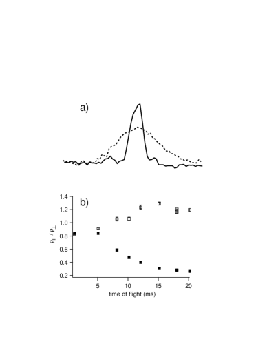
We studied the dynamics of the condensate in a stationary lattice by observing the free expansion of a condensate adiabatically loaded into the lattice. In order to load the condensate into the optical lattice, after adiabatically reducing the mean magnetic trap frequency to the desired value we linearly increased the lattice depth from to in a time . Since typically the chemical potentials of our condensates in traps with frequencies lie between and , the adiabaticity condition [11] was satisfied even for small chemical potentials. After that, only the magnetic trap was switched off and the condensate was imaged after a variable time of free expansion inside the optical lattice. The effect of a deep lattice on the free expansion is clearly evident in the condensate images of Fig. 1 (a) and in the measurements of the condensate aspect ratio shown in Fig. 1 (b) ( denoting the half-widths of Gaussian fits to the density profile in the lattice direction and perpendicular to it, respectively). As in the presence of the lattice the condensate does not expand at all in the lattice direction, the aspect ratio drops off sharply with increasing time-of-flight as the BEC expands in the (unbound) perpendicular direction. The lack of expansion in the lattice direction reflects the fact that the condensate has effectively been split up into several smaller condensates confined in the individual lattice wells. In the perpendicular direction we have observed an enhanced expansion when the lattice is present, which can be explained by the increase in the chemical potential when the lattice is ramped up (as calculated by Pedri et al. [3]).
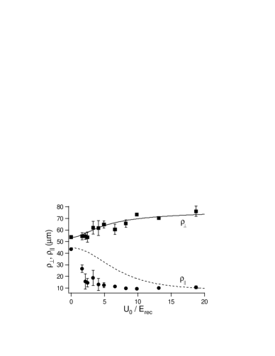
We modeled the expansion of the condensate in the presence of the 1D lattice using the equations derived in [12, 13] with a slight modification along the lines of Ref. [4]: In the ansatz leading to the differential equation of [12] for the scaling factor along the lattice direction we replaced the atomic mass by the effective mass , introduced in [4] in analogy with a solid state physics approach, as derived from a band structure calculation for a periodic potential of depth . As can be seen in Fig. 2, taking into account the variation of the chemical potential with this model reproduces well our experimental data for the perpendicular expansion of the condensate (the theoretical plots are corrected for the resolution of our imaging system).
For the lattice direction, this approach gives the correct result for deep lattices (), for which intuitively one expects the condensate to be broken up and the individual parts to be essentially confined to the lattice wells, suppressing the expansion along the lattice direction. The qualitative behaviour in the intermediate regime () is also reasonably well reproduced. We find, however, that the experimental expansion along the lattice direction is considerably less than the theoretical prediction in the intermediate regime. We have checked that taking into account the finite momentum spread of the condensate when calculating the effective mass only leads to a correction on the percent level and thus cannot explain the deviation of our experimental data from the numerical calculations neglecting mean field corrections. This might indicate that there are effects such as self-trapping [2] due to the mean-field interaction that further reduce the expansion in the lattice direction. Another hint in this direction is given by the fact that when we vary the number of atoms in the condensate, for large the width in the lattice direction of the expanded condensate actually starts to decrease rather than increase. Again, this might be explained by mean-field effects which become important in the dynamics of the condensate expansion when gets large, with non-linear effects like self-trapping reducing the observed width .
As described in detail in [14], we could also directly deduce from our data the dependence of the chemical potential on from the initial perpendicular size of the condensate in the presence of the lattice inferred from the size measured after an expansion time and the ratio of the scale factor . The chemical potential thus measured agrees well with the prediction of [3].
Finally, we note here that in the limit of large lattice depths, the adiabatic loading of a BEC into and optical lattices effectively realizes an adiabatic transformation between a 3D condensate and an array of 2D condensates. The condition of Ref. [15] (where is the harmonic approximation for the oscillation frequency in a lattice well) for the condensates in each well to be in the 2D limit is always satisfied for the small number of atoms in a single well () present in our experiment. For an array of 2D condensates obtained by creating the condensate in the combined potential of the harmonic trap and the lattice, Burger et al. [16] have shown that in the case of their cigar-shaped condensate (with the long axis along the lattice direction), the transition temperature in the presence of the lattice is significantly lower than in the 3D case (i.e. in the magnetic trap without the lattice). Calculating the critical temperature along the same lines for our system, we find that due to the larger number of atoms per lattice site in our geometry, and hence we expect no significant change in the condensate fraction in the presence of the lattice. In fact, experimentally we even find a consistently larger condensate fraction after ramping up the lattice, as seen in Fig. 3. This result indicates that, with an appropriate choice of parameters, a 1D optical lattice could be used to investigate adiabatic transformations between 3D and 2D condensates which could, e.g., be exploited to create condensates from thermal clouds by changing the dimensionality of the system, as recently proposed by Olshani and Weiss [19], similarly to the change in the shape of the potentials in Refs [17, 18] for other geometries.
IV Phase evolution: Behaviour of the interference pattern
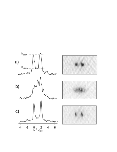
In order to study the phase evolution of a condensate in an optical lattice, we performed a non-adiabatic loading procedure, meaning that the condensate initially was not in the ground state of the combined potential of the magnetic trap and the optical lattice. In a typical experiment, the optical lattice was ramped up in , after which the potential was kept at its maximum value for a holding time . At the end of the holding time, the lattice was accelerated in to one (lattice) recoil velocity by chirping the frequency difference between the lattice beams. Immediately after that, both the lattice and the magnetic trap were switched off. After a time-of-flight of , the expanded condensate was imaged using a resonant probe flash. Figure 4 shows typical absorption images and integrated lines profiles obtained in this manner for different holding times. For short times, a clean double-peak structure is visible, as expected from the interference between the condensates expanding from the individual lattice wells (with a phase difference between them due to the final acceleration). During the first few milliseconds, this pattern evolves into a more complicated structure featuring several additional peaks, and finally washes out completely, resulting in a single Gaussian-shaped lump. For long waiting times, the two-peaked structure reappears.
Intuitively, these results can interpreted as follows. Initially, the condensate is broken up into several pieces when the optical lattice is abruptly switched on, and the condensate fragments are locally compressed. This leads to a different (local) chemical potential and hence a different phase evolution at the individual lattice sites. As a result, the interference pattern after a time-of-flight evolves from a clean two-peaked structure (all condensate fragments in phase) into a broad Gaussian distribution, reflecting the fact that the individual fragments have accumulated different phases. For long holding times, a common phase is re-established through tunneling between adjacent lattice sites and dissipation of energy into higher-lying modes (more detailed studies of these phenomena are under way).
In order to quantify the degree of coherence between the lattice sites, we characterized the interference pattern (integrated perpendicular to the lattice direction) through a visibility calculated as
| (1) |
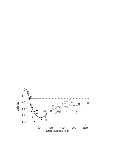
where is the mean value of the absorption image at the position of the two peaks, and is the value of the absorption image mid-way between the two peaks (averaged over a range of of the peak separation) as illustrated in Fig. 4 (a). In a typical experiment, initially rapidly decreases from a value of to roughly within , depending on the trap frequency (see Fig. 5). If the lattice depth is kept constant throughout, for trap frequencies the visibility then typically rises again and begins to fluctuate in an apparently random manner for a few tens of milliseconds. Finally, these fluctuations die out and stabilizes at a value close to the initial visibility.
For weak magnetic traps with , after the initial decay in visibility stays close to for up to . Under these conditions, we could induce a faster revival of the interference pattern by lowering the optical lattice depth and hence increasing the tunneling rate between adjacent lattice wells. Fig. 5 shows the initial decay for a lattice depth of and the subsequent revival when the lattice is lowered to .
The interpretation of the phase evolution is complicated by the fact that when the lattice is switched on non-adiabatically, radial oscillations of the condensate are also excited. These oscillations damp out after a few cycles. Also, the temperature of the condensate initially rises and levels out at a higher value. In our experiments, (where is the critical temperature for condensation) typically rises from to . This re-thermalization, which takes places on a timescale that is comparable both to the damping time of the radial oscillations and the revival time of the visibility at fixed lattice depth, may take place through a re-distribution of energy into higher-lying modes of the condensate. Theoretical studies of these processes are currently being carried out.
V Conclusions and outlook
In a stationary optical lattice, both dynamical and phase properties of a BEC can be studied. By adiabatically loading the BEC into the lattice, we have studied its free expansion after switching off the magnetic trap. From the expansion perpendicular to the lattice direction we were able to deduce the chemical potential of the BEC in the lattice as a function of the lattice depth. The expansion in the lattice direction for small lattice depths still needs further investigation as it is not well reproduced by a simple treatment involving the effective mass. Non-linear effects might come into play, possibly reducing the expansion through self-trapping.
The phase evolution of a condensate non-adiabatically loaded into a lattice is another intriguing area of study that deserves closer investigation. We have observed an initial decay of the interference pattern followed, for long holding times, by an almost complete revival. The role of tunneling in this revival is evident from the fact that when the lattice depth is lowered after the initial dephasing period, a revival in the visibility is induced. The interplay between tunneling, re-thermalization and damping of the radial oscillations excited by the non-adiabatic switch-on of the lattice needs to be looked at more closely in future investigations. In particular, the role of the non-condensed fraction needs to be elucidated.
Acknowledgments
The authors wish to thank P.B. Blakie, C.J. Williams, P.S. Julienne, S. Stringari and Y. Castin for useful discussions. This work was supported by the MURST (PRIN2000 Initiative), the INFM (Progetto di Ricerca Avanzata ‘Photonmatter’), and by the the EU through the Cold Quantum Gases Network, Contract No. HPRN-CT-2000-00125. O.M. gratefully acknowledges a Marie Curie Fellowship from the EU within the IHP Programme.
REFERENCES
- [1] Javanainen, J., 1999, Phys. Rev. A 60, 4902
- [2] Trombettoni, A. and Smerzi, A., 2001, Phys. Rev. Lett. 86, 2353
- [3] Pedri, P., Pitaevskii, L., Stringari, S. et al., 2001, Phys. Rev. Lett. 87, 220401
- [4] Krämer, M., Pitaevskii, L., and Stringari, S., 2002, Phys. Rev. Lett. 88, 180404
- [5] Orzel, C., Tuchman, A.K., Fenselau, M.L. et al., 2001, Science 291, 5512
- [6] Greiner, M., Mandel, O., Esslinger, T. et al., 2002, Nature (London) 415, 6867
- [7] Morsch, O., Müller, J.H., Cristiani, M. et al., 2001, Phys. Rev. Lett. 87, 140402
- [8] Hensinger, W.K., Haffner, H., Browaeys, A. et al., 2001, Nature 412, 6842
- [9] Cristiani, M., Morsch, O., Müller, J.H. et al., 2002, Phys. Rev. A 65, 063612
- [10] For simplicity, in the following we shall assume that the lattice direction is along . The different frequencies along the lattice direction and perpendicular to it will be denoted by and , respectively.
- [11] Band, Y.B. and Trippenbach, M., 2002, Phys. Rev. A 65, 053602
- [12] Castin, Y. and Dum, R., 1996, Phys. Rev. Lett. 77, 5315
- [13] Kagan, Yu., Surkov, E.L., and Shlyapnikov, G.V., 1996, Phys. Rev. A 54, 1753; Pitaevskii, L.P., 1996, Phys. Lett. A 221, 14
- [14] Morsch, O., Cristiani, M., Müller, J.H. et al., 2002, Phys. Rev. A 66, 021601(R)
- [15] Görlitz, A., Vogels, J.M., Leanhardt, A.E. et al., 2001, Phys. Rev. Lett. 87, 130402
- [16] Burger, S., Cataliotti, F.S., Fort, C. et al., 2002, Europhys. Lett. 57, 1
- [17] Stamper-Kurn, D.M., Chikkatur, A.P., Görlitz, A. et al., 1999, Phys. Rev. Lett. 83, 2876
- [18] Pinkse, P.W.H., Mosk, A., Weidemüller, M. et al., 1997, Phys. Rev. Lett. 78, 990
- [19] Olshanii, M. and Weiss, D., 2002, Phys. Rev. Lett. 89, 090404