Resonant propagation of fluxons in corner junctions with triplet pairing symmetry
Abstract
We present the numerical solutions for the characteristics, and describe the motion of fluxons in a frustrated Josephson junction made of an unconventional triplet superconductor and an -wave superconductor. In the inline geometry, and long length limit the moving integer fluxon interacts with the bound fractional fluxon but is not able to change its position or polarity. We observe different modes of multifluxon propagation. In the small length limit the moving fluxon is a combination of the stable solutions that exist in the static case and additional steps are introduced in the diagram.
pacs:
74.50.+r,74.20.Rp,74.60.Jg,85.25.HvI Introduction
The order parameter symmetry in the recently discovered superconductor Sr2RuO4 [1] is an active area of current work. The Knight shift shows no change when passing through the superconducting state and this indicates that the pairing state is triplet [2]. The magnetic field is spontaneously induced as shown by experiment, and this is a clear indication that the time-reversal symmetry is broken [3]. Inelastic-neutron-scattering measurements on single crystals of Sr2RuO4 show that the pairing state is highly anisotropic [4]. Also specific heat measurements support the scenario of line nodes within the gap as in high- cuprate superconductors [5].
In Josephson junctions made of unconventional -wave superconductors, the Josephson critical current can be negative depending on the orientation angles of the crystallographic axes with respect to the junction interface. A negative critical current can be thought of as a phase shift of at the junction interface. A half fluxon (antifluxon) is trapped at a junction. It’s existence is confirmed experimentally by measurements of the critical current versus the magnetic flux in corner junctions or corner SQUID where a dip appears in the critical current for magnetic field equal to zero [7]. The half magnetic flux quantum, ( fluxon) has been directly observed using a scanning superconducting quantum interference device microscope in tricrystal frustrated junctions in superconducting YBa2Cu3O7-δ [6].
The static properties of one dimensional frustrated Josephson junctions between singlet and triplet superconductors have been presented for different nodal and nodeless pairing states [8]. The critical current and the spontaneous flux show a characteristic modulation with the junction orientation, which can be tested by experiment.
The Josephson junction between -wave superconductors supports modes of resonant propagation of fluxons [9]. In the plot of the current-voltage () characteristics these modes appear as near-constant voltage branches known as zero field steps (ZFS) [10, 11]. They occur in the absence of any external field. The ZFS appear at integer multiplies of , where is the velocity of the electromagnetic waves in the junction, and is the junction length. The moving soliton is accompanied by a voltage pulse which can be detected at the junction’s edges.
In Josephson junctions made of unconventional -wave superconductors the bound half-fluxon (-antifluxon) reverses its sign and emits an integer fluxon (antifluxon) when biased by an external current [12, 13, 14]. In this work we study the dynamic properties of a frustrated junction, between singlet and triplet superconductors and calculate the characteristics. For the triplet superconductor Sr2RuO4 we shall assume two possible pairing states of two dimensional order parameter, breaking the time reversal symmetry. The first one is the nodeless -wave order parameter with symmetry [15]. The other one is the -wave state proposed by Hasegawa et al., having symmetry [16].
We study both the long and short length junction limit. In the long length junction limit, the external current cannot move the fractional fluxon (antifluxon) which is confined at and the ZES exist at integer values of the dc voltage . In the short length junction limit, additional modes in the diagram are introduced at half integer values of the dc voltage and this can be used to distinguish the possible pairing states in the junction.
In the following we present the theoretical model for the corner junction in Sec. II. We present the results for the large junction limit in Sec. III. The case of the shorter junction is presented in Sec. IV and finish with the conclusions.
II Corner junction model
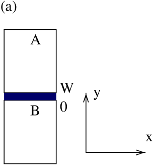
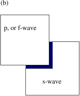
We consider the junction shown in Fig. 1(a) between a triplet superconductor with a two component order parameter and an -wave superconductor . The Ginzburg - Landau (GL) equations for isotropic p-wave superconductors have been derived microscopically based on Gor’kov’s theory [17]. This derivation is closely compared to the GL free energy for the superconducting state composed of two degenerate components. Applying the boundary conditions at and where is the width of the interface we derive the following current phase relation [8]
| (1) |
where is defined as the relative phase difference between the two superconductors and is the intrinsic phase difference. is the Josephson critical current density. For the type of junction that we consider where the insulator has a definite thickness and it is not a point contact as in the case treated by Barash et al. [18], the Josephson effect is strongly directional dependent and the possibility for the tunneling of the Cooper pairs becomes maximum when the trajectory of the Cooper pair is vertical to the interface. So the total momentum of the order parameter functional depends only on the orientation of the interface. This dependence enters the current phase relation via the , and . We consider a corner Josephson junction between the superconductor and the superconductor as seen in Fig. 1(b). The orientation of the and crystallographic axes are at right angles with the junction edges. We map the two segments of this junction each of length into a one dimensional axis. The characteristic phases , for the two segments, for the pairing states that we consider can be seen in table I. The superconducting phase difference across the junction is then the solution of the sine-Gordon equation
| (2) |
where is the damping constant which depends on the temperature. The inline boundary condition reads
| (3) |
where is the inline bias current. The length is normalized in units of the Josephson penetration depth given by
| (4) |
where is the sum of the penetration depths in two superconductors plus the thickness of the insulator layer. The time is in units of the inverse of the Josephson plasma frequency
| (5) |
We can classify the different solutions obtained from Eq. 2 with their magnetic flux content, in units of the flux quantum
| (6) |
where is the value of the phase at the left(right) edge of the junction.
III large junction limit
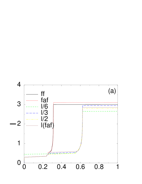
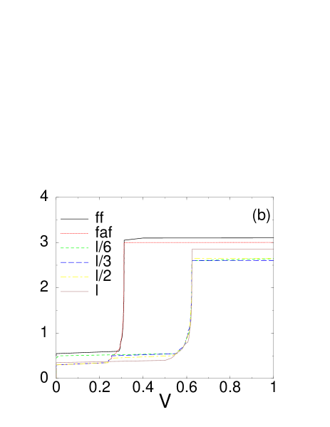
A order Runge Kutta method with fixed time step , was used for the integration of the equations of motion. The number of grid points is , and the junction length is . The damping coefficient is used in all the calculations. The characteristics for the first and second ZFS (corresponding to one and two fluxons moving into the junction) are seen in Fig. 2(a) for the and in Fig. 2(b) for the pairing state. For the first ZFS two different modes of fluxon propagation exist, corresponding to the presence of bound fractional fluxon or antifluxon respectively at the junction center. For the case, due to the difference in the flux content of the bound solutions, the has smaller critical current than the . This is opposite to the case. In the wave case the curves for the first ZFS, for the and mode have equal critical currents [14].
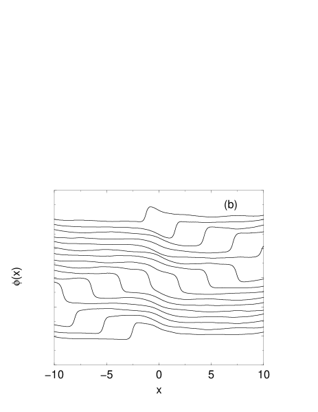
For the case, the external current cannot move the with which is confined at (see Fig. 3(a)). By applying the external current it emits an integer antifluxon () which moves to the right and converts to an with . The hits the right boundary and transforms into a fluxon () which moves to the left. When the reaches the center drags the with it for a while and forms a fluxon with flux which then breaks into a and a moving to the left. The fluxon hits the left boundary transforms into an antifluxon which moves to the center where it meets the oscillating and interacts with it forming a and the period has been completed. A full period of motion back and forth takes time , and since the overall phase advance is , in the relativistic limit where reached at high currents, the dc voltage across the junction will be .
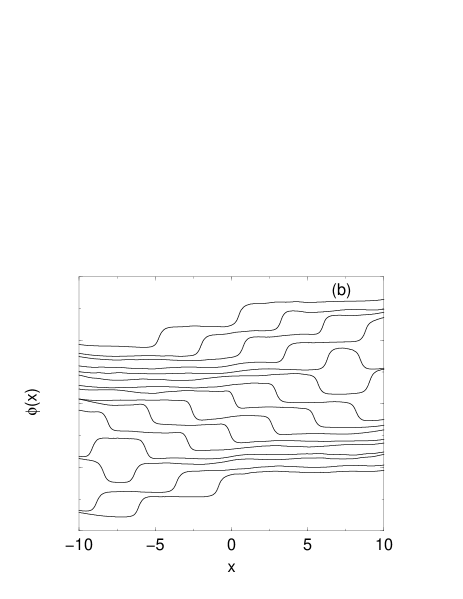
We may also have the situation where the with exists at the junction center as seen in Fig. 3(b). By applying an external current it emits an integer fluxon which moves to the left and converts to a with . The hits the left boundary and transforms to an which moves to the right. When the reaches the center it meets the oscillating and forms a large antifluxon with which then splits into a with and an integer antifluxon moving to the right. The antifluxon hits the right boundary, transforms into a fluxon which moves to the center where it meets the oscillating , interacts with it forming a and the period has been completed. For the pairing state the has magnetic flux while the has magnet flux and an integer fluxon or antifluxon propagates into the junction and interacts with the trapped fluxon or antifluxon.
The different character of the various fluxon solutions can also be seen from the plot of the instantaneous voltage at the center of the junction for the various fluxon configurations. That plot is seen in Fig. 4 for the solutions regarding the first ZFS for the state. During the time of one period three peaks appear in this plot by the time the fluxon (antifluxon) passes through the junction center. Note that the characteristic oscillations of between the peaks are due to the oscillation of the bound solution about the junction center. These oscillations become more distinguishable in the case due its larger fluxon content. Note also the difference in height between successive peaks in the vs diagram. This difference become more pronounced in the case due to its larger flux content. The plot of at the edges shows two peaks during the time of one period at time instants which differ by half a period. So for the first ZFS the vs plot can be used to probe the existence of or at the junction center. For the pairing state (not presented in the figure) the has larger flux and the difference in the peak heights and the inter-peak oscillations become more distinguishable in the case.
For the second ZFS we found four two-fluxon configurations with distinct curves. Depending on the distance between the two vortices which is kept constant we can categorize the solutions as seen in Fig. 5. So compared to the case of conventional -wave superconductors [11] junction we observe several curves for the second ZFS depending on the relative distance between the fluxons and this may be used to probe the presence of intrinsic magnetic flux.
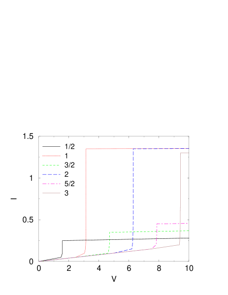
IV shorter junction limit
We now consider the case where the junction is of relative short length . We plot in Fig. 6 the characteristics for the ZFS. We see that additional steps appear at half integer values of the dc voltage besides the ones that exist at integer values. In Fig. 7(a) we present , for the first ZFS, for one period () at various instances in time, which are separated by . For the case, for a with exists at the junction center. By applying the external current it converts to a with and a with . The drags the with it forming a combination of fractional fluxon-antifluxon (), with negative magnetic flux which moves to the right. It hits the right boundary and the fractional antifluxon with goes to a fractional fluxon with , while the fractional fluxon with goes to a fractional antifluxon with , forming again a combination of fractional fluxon-antifluxon () with total flux , which moves to the left. Although the total flux is half integer the moving fluxon to the right direction has different structure than the combination that moves to the left and this explains the asymmetry between successive peaks in the diagram seen in Fig. 8(a). The hits the left boundary transforms into an with which moves to the center where the period is completed. A full period of motion back and forth takes time , and since the overall phase advance is , in the relativistic limit where reached at high currents, the dc voltage across the junction will be . This is indeed the value obtained from the numerical simulation as seen in Fig. 6 for the solution labeled as . Note that this value is half than the case where a full fluxon moves into the junction.
In Fig. 7(c) we present , for the case where a bound combination of two fractional vortices with total magnetic flux is propagating into the junction. In a junction of length the propagating fluxon accomplishes an overall phase advance of in a full period . Thus the dc voltage across the junction will be . The ZFS seen in Fig. 6 corresponds to a solution labeled as . Note the the structure of the fluxon moving in the forward and backward direction is not the same and the successive peaks in the vs at the center of the junction do not have equal heights as seen in Fig. 8(c).
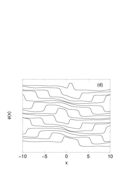
In Fig. 7(d) we present , for the case where the moving combination corresponds to magnetic flux equal to . Thus the dc voltage across the junction will be . The corresponding ZFS is labeled as in Fig. 6. Due to symmetry the vs at the center of the junction will have the same height for the forward and backward direction as seen in Fig. 8(d).
For the state for the first ZFS, by increasing the bias current, the with is transformed into a with and a with forming a fractional fluxon with total flux that moves to the right. The reflected fluxons has but differently to the case it is composed by a with and a with . This difference can be seen in the vs diagram at the center which is displaced in time by half a period compared to the case. However the resulting are similar to the case.
V conclusions
We analyzed the dynamics of fluxons moving in a frustrated Josephson junction with triplet pairing symmetry, and calculated the characteristics. The external current cannot move the which is confined at . However the external current is able to reorient the and emit an integer fluxon(antifluxon). For the first ZFS we found two distinct curves with different critical currents, which correspond to the case where the moving fluxon or antifluxon interacts with a bound fractional fluxon and antifluxon respectively. The critical currents are different for the and the pairing states and this can be used to distinguish the pairing symmetry. When there are more than one integer vortices moving in the junction, there is a possibility of different modes of fluxon propagation which correspond to different critical currents.
In the small junction limit, due to the presence of the internal flux, the moving integer or half integer vortices will have internal structure that is formed from the combinations of the static solutions. The different modes in the diagram exist both at integer and half integer values of the dc voltage. However the is similar for the and and therefore it can not be used to distinguish between the two pairing states.
VI acknowledgements
Part of this work was done at the Department of Physics, University of Crete, Greece.
REFERENCES
- [1] Y. Maeno, H. Hashimoto, K. Yoshida, S. Nishizaki, T. Fujita, G.J. Bednorz and F. Lichtenberg, Nature 372, 532 (1994).
- [2] K. Ishida, H. Mukuda, Y. Kitaoka, K. Asayama, Z.Q. Mao, Y. Mori, and Y. Maeno, Nature 396, 658 (1998).
- [3] G.M. Luke, Y. Fukamoto, K.M. Kojima, M.L. Larkin, J. Merrin, B. Nachumi, Y.J. Uemura, Y. Maeno, Z.Q. Mao, Y. Mori, H. Nakamura, and M. Sigrist, Nature 394, 558 (1998).
- [4] F. Servant, B. Fak, S. Raymond, J.P. Brison, P. Lejay, and J. Flouquet, Phys. Rev. B 65, 184511 (2002).
- [5] S. Nishizaki, Y. Maeno, and Z. Mao, J. Phys. Soc. Jpn. 69, 572 (2000).
- [6] C.C. Tsuei, J.R. Kirtley, C.C. Chi, Lock See Yu-Jahnes, A. Gupta, T. Shaw, J.Z. Sun, and M. B. Ketchen, Phys. Rev. Lett. 73, 593 (1994).
- [7] D.A. Wollman, D.J. Van Harlingen, J. Giapintzakis, and D.M. Ginsberg, Phys. Rev. Lett. 74, 797 (1995).
- [8] N. Stefanakis, Phys. Rev. B 65, 064533 (2002).
- [9] T.A. Fulton and R.C. Dynes, Soild State Commum. 12, 57 (1973).
- [10] J.T. Chen, T.F. Finnegan and D.N. Langenberg, Physica 55, 413 (1971).
- [11] P.S. Lomdahl, O.H. Soerensen, and P.L. Christiansen, Phys. Rev. B 25, 5737 (1982).
- [12] A.B.Kuklov, V.S. Boyko, and J. Malinsky, Phys. Rev. B 51, 11 965 (1995).
- [13] T. Kato and M. Imada, J. Phys. Soc. Jpn. 66, 1445 (1997).
- [14] N. Stefanakis, Unpublished.
- [15] T.M. Rice and M. Sigrist, J. Phys.: Condens. Matter 7, L643 (1995).
- [16] Y. Hasegawa, K. Machida, and M. Ozaki, J. Phys. Soc. Jpn. 69, 336 (2000).
- [17] J.-X. Zhu, C.S. Ting, J.L. Shen, and Z.D. Wang, Phys. Rev. B 56, 14093 (1997).
- [18] Yu.S. Barash, A.M. Bobkov, and M. Fogelstr m Phys. Rev. B 64, 214503 (2001).
| Pairing state | ||
|---|---|---|