Roughness of Interfacial Crack Front: Correlated Percolation in the Damage Zone
Abstract
We show that the roughness exponent of an in-plane crack front slowly propagating along a heterogeneous interface embeded in a elastic body, is in full agreement with a correlated percolation problem in a linear gradient. We obtain where is the correlation length critical exponent. We develop an elastic brittle model based on both the 3D Green function in an elastic half-space and a discrete interface of brittle fibers and find numerically that . We conjecture it to be 3/2. This yields . We also obtain by direct numerical simulations in excellent agreement with our prediction. This modelling is for the first time in close agreement with experimental observations.
pacs:
83.80.Ab, 62.20.Mk, 81.40.NpAn important motivation for studying interfacial crack pinning srvm95 ; sm97 is to simplify the study of the origin of the scaling properties of brittle crack surfaces mpp84 ; bs85 . These scaling properties are seen, for example, in the height-height correlation of the fracture roughness (i.e. out-plane roughness), which shows self-affinity. That is, the conditional probability density , i.e. the probability that the crack surface passes within of the height at position when it had height zero at , shows the invariance
| (1) |
where is the roughness exponent. It is now generally believed that the roughness exponent shows a universal value of about 0.80 at larger scales blp90-mhhr92-sgr93-cw93-sss95 , while a lower value of about 0.5 might be seen at smaller scales dhbc96-dnbc97 .
Direct observations of the interfacial crack-pinning have been performed recently. The problem consists of following the roughness of a crack front moving along the flat interface between two elastically connected blocks. The experimental study of constrained crack propagation between two sintered plexiglass plates presented in sm97 resulted in the estimate of the in-plane roughness exponent: . This work was followed by a longer study leading to the estimate dsm99 . A recent study of the motion of a helium-4 meniscus along a disordered substrate — a problem closely related to the motion of a crack line — gave prg02 .
Numerous models for interfacial crack propogation in heterogeneous material have been proposed. The numerical simulation presented in srvm95 is based on a perturbative Green function approach following the quasistatic evolution of the interfacial crack front position gr89 , which is treated as a single-valued function of position along the orthogonal direction to the crack advancement direction, and time . The linearized Green function used binds together points only along the fracture front. The stress intensity factor at a point along the fracture front is then found to be
| (2) |
where is the stress intensity factor that would result if the crack were straight gr89 . The fracture is advanced by identifying the most stressed point along the fracture line and advancing this by a small step. The roughness exponent of the crack front was estimated numerically to be , while a direct dynamical renormalization group calculation gave to lowest order ek94 . Higher-order corrections to this quasistatic analysis increases the value of to 0.48 cdw01 , while a different quasistatic analytical technique suggests rk02 . Dynamic effects have beeen largely studied numerically and analytically pr94-rf97-rf98-mr98-mr00 , in particular in the form of crack front waves. They lead to an increased roughness exponent compared to the initial 1/3-value up to but still smaller than experimental observations.
Hence, the situation today is that there is a large and significant discrepancy between theoretical and experimental estimates: theoretical estimates being considerably smaller than the experimental ones.

In this letter we present a numerical calculation of the roughness exponent of a crack front that propagates quasi-statically along a heterogeneous interface, based on a Green function technique which differs from that previously used. Indeed it does not reduce the crack tip to a single tortuous line but describes the tip as a region of interactions between microcracks (see Fig. 1). Our technique is based on the static solution of the elastic equations for the deformation of the surface of an elastic half space ll58 . The local deformation, , at position along the plane is related to the normal stress field by the expression
| (3) |
where the Green function is j85 :
| (4) |
with is the Poisson ratio and the elastic constant. For large , . For the sake of simplicity, as generally done for the study of contact between two elastic bodies j85 , we substitute one of the elastic plates by an infinitely rigid one. The other plate is modeled as an elastic block for which Eq. (4) is valid. We discretize the model, so that the forces and deformations are described by the discrete version of Eq. (3),
| (5) |
is the Green function Eq. (4) averaged over an area ,
| (6) |
where is the lattice spacing, is the deformation of the elastic body at site , and the force acting at that point. The indices and in Eq. 5 run over all sites.
The elastic block is connected to the infinitely stiff plate by a discrete interface made of an array of elastic harmonic springs. Each spring is brittle and has a breaking threshold randomly drawn from a uniform distribution between zero and one. The spacing between the springs is in both the and directions. The force that an unbroken spring is carrying, is transferred over an area of size to the soft surface and given by Hooke’s law:
| (7) |
where is the spring constant ( for all springs). is the displacement of the infinitely stiff medium, and is a function of , i.e. solid rotation of the stiff medium. The quantity is, therefore, the length that spring is stretched. We assume periodic boundary conditions both in the and directions. In order to model the mode I fracturing of the interface between the two media (Double Cantilever Beam (DCB) test) in a way compatible with the biperiodic boundary conditions, we let be wedgeshaped with a maximum at and , and zero for (i.e. mirroring conditions). The load the system, is increased and the springs break one by one. The numerical technique to solve the equations that ensue is presented in detail in bhs02 .
We show in Fig. 1 a typical damage front in a system. We define the fracture front in this model as the set of nodes that form a continuous path separating the infinite cluster of broken springs from the infinite cluster of unbroken springs. This definition is similar to that of Ref. sm97 . From Fig. 1, we clearly see that even if a front can be defined, an extended damage zone exists. Accordingly the front does not capture all the active tip of the fracture. This observation supports the relevance of a non line description of the crack front.
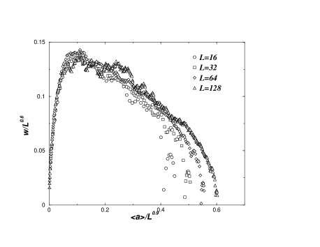
In Fig. 2, we show the width of the fracture front as a function of its average position — which acts as a time parameter in this quasi-static model, for various system sizes. By collapsing the width evolution for the different system sizes, we see that the crack front follows a Family-Vicsek scaling fv85 . Two important exponents are, thus, obtained: the roughness exponent and dynamical exponent . The roughness exponent is in close agreement with the experimentally obtained value sm97 ; dsm99 ; ms01 ; prg02 , while the dynamical exponent was found in Ref. ms01 to be .
Our model distinguishes itself from earlier numerical models in three major ways: (1) Most previous models are based on a small perturbation approach and include linearizations gr89 that are not used here. Furthermore, it was assumed in the earlier studies that (2) the fracture line was a single-valued function, hence ruling out overhangs. This assumption prevents islands of unbroken bonds from forming in the wake of the advancing fracture line. (3) The assumption of a single advancing fracture line also prevents the formation of a damage zone in front of the fracture line. None of these three assumptions are necessary in the present model. In order to test whether assumptions (2) or (3) are responsible for the difference in roughness exponent, we imposed both on the present model. No change in was observed. Hence, we conclude that it is the linearization assumption that is responsable for the difference.

In the following, we demonstrate that the roughness exponent is a result of a correlated percolation process in a gradient imposed by the mode I loading of the system. We start by charactarizing the correlated percolation. For this goal, we consider a similar problem but where the loading is obtained without any gradient, i.e. horizontal and parallel displacement of the rigid medium bhs02 . In this case, when the homogeneous displacement of the rigid medium reaches a maximum value, the system goes unstable, and unless is decreased again, catastrophic failure sets in. In Ref. bhs02 , the size distribution of clusters of broken springs was studied, and a power law was found with an exponent . This value is different from ordinary percolation where sa92 and shows that correlated percolation takes place. In Fig. 3, we show the fluctuations of density of broken springs at . If there is a diverging correlation length in the problem, these fluctuations scale as . We find that , leading to . We conjecture that the exact value is . Hence, the fracture process in this system is in a universality class which is different from standard percolation where .
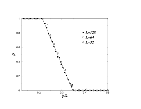
When is no longer constant, but is given by the wedge shape (DCB load), the form of interactions between the springs does not change. Hence, the critical properties of the model when run in the “horizontal” mode are still present under DCB loading. The wedge shape of leads to a gradient in the loading of the springs, going from very high loading where the damage is large to very low loading well into the still intact part of the interface. In Fig. 4, we show the damage profile , i.e. the density of broken springs averaged in the direction, for systems of different sizes. The profile is clearly linear. Somewhere along this damage profile, there is a line in the -direction at where the damage density is critical, . In the vicinity of this line, there is a critical region which is characterized by being on the edge between stability and instability and corresponds to the crack front. Following the arguments of Sapoval et al. for percolation in a gradient srg85 , if follows a linear law,
| (8) |
on the interval , where is the length scale characterizing the width of the damage zone, then is the position of the fracture front (when ignoring small corrections for finite-size systems). The critical region has a width which is related to the damage as . Eliminating between these two expressions for gives
| (9) |
Since the gradient in is inversely proportional to and the average strength of the springs does not change with , we have that
| (10) |
In Fig. 4, the reduced variable was used resulting in data collapse for different system sizes, thus validating Eq. (10). Furthermore, the width of the fracture front, is proportional to the width of the critical region . Hence, we find
| (11) |
where we have used our estimate . This result is in excellent agreement with our numerical simulations and with the experimental results.
A similar idea has been proposed for the outplane roughness of fracture surfaces where the gradient and the exponent are different and leads to in excellent agreement with the experimental value 0.80 hs02 . We finally note that Zapperi et al. zhr00 have pointed out the connection between gradient percolation and the interface fracture problem in the limit of infinitely stiff plates. We have shown in this letter that this mechanism stays intact also when the plates do respond elastically. However, the universality class of the corresponding correlated percolation problem is different from ordinary percolation, leading to the observed roughness exponent rather than 4/7 for ordinary percolation in a gradient.
This work was partially funded by the CNRS PICS contract and the Norwegian Research Council, NFR. J.S. and A.H. thank Fernando A. Oliveira and the ICCMP for financial support during our stay in Brasília. Discussions with K. J. Måløy are gratefully acknowledged.
References
- (1) J. Schmittbuhl, S. Roux, J. P. Vilotte and K. J. Måløy, Phys. Rev. Lett. 74, 1787 (1995).
- (2) J. Schmittbuhl and K. J. Måloy, Phys. Rev. Lett. 78, 3888 (1997).
- (3) B. B. Mandelbrot, D. E. Passoja, and A. J. Paullay, Nature 308, 721 (1984).
- (4) S. R. Brown and C. H. Scholz, J. Geophys. Res. 90, 12575 (1985).
- (5) E. Bouchaud, G. Lapasset, and J. Planés, Europhys. Lett. 13, 73 (1990); K. J. Måløy, A. Hansen, E. L. Hinrichsen, and S. Roux, Phys. Rev. Lett. 68, 213 (1992); J. Schmittbuhl, S. Gentier, and S. Roux, Geophys. Res. Lett. 20, 639 (1993); B. L. Cox and J. S. Y. Wang, Fractals, 1, 87 (1993); J. Schmittbuhl, F. Schmitt, and C. H. Scholz, J. Geophys. Res. 100, 5953 (1995).
- (6) P. Daugier, S. Henaux, E. Bouchaud, F. Creuzet, Phys. Rev. E 53, 5637 (1996); P. Daugier, B. Nghiem, E. Bouchaud and F. Creuzet, Phys. Rev. Lett. 78, 1062 (1997).
- (7) A. Delaplace, J. Schmittbuhl and K. J. Måløy, Phys. Rev. E 60, 1337 (1999).
- (8) K. J. Måløy and J. Schmittbuhl, Phys. Rev. Lett. 87, 105502 (2001).
- (9) A. Prevost, E. Rolley and C. Guthmann, Phys. Rev. B 65, 064517 (2002).
- (10) H. Gao and J. R. Rice, ASME J. Appl. Mech. 56, 828 (1989).
- (11) D. Ertas and M. Kardar, Phys. Rev. E, 49, 2532 (1994).
- (12) P. Chauve, P. Le Doussal and K.J. Wiese Phys. Rev. Lett. 86, 1785 (2001).
- (13) A. Rosso and W. Krauth, Phys. Rev. E, 65, 025101 (2002).
- (14) G. Perrin and J. R. Rice, J. Mech. Phys. Solids, 42, 1047 (1994); S. Ramanathan and D. S. Fisher, Phys. Rev. Lett. 79, 877 (1997); S. Ramanathan and D. S. Fisher, Phys. Rev. B, 58, 6026 (1998); J. W. Morrissey and J. R. Rice, J. Mech. Phys. Solids, 46, 467 (1998); J. W. Morrissey and J. R. Rice, J. Mech. Phys. Solids, 48, 1229 (2000).
- (15) L. Landau and E. M. Lifshitz, Theory of Elasticity (Clarendon Press, Oxford, 1958).
- (16) K. L. Johnson, Contact Mechanics (Cambridge Univ. Press, Cambridge, 1985).
- (17) G. G. Batrouni, A. Hansen and J. Schmittbuhl, Phys. Rev. E, 65, 036126 (2002).
- (18) F. Family and T. Vicsek, J. Phys. A, 18, L75 (1985).
- (19) A. Hansen and J. Schmittbuhl, Cond-mat/0207360 (2002).
- (20) D. Stauffer and A. Aharony, Introduction to percolation theory (Francis and Taylor, London, 1992).
- (21) B. Sapoval, M. Rosso and J.F. Gouyet, J. Phys. Lett. (France) 46, L149 (1985).
- (22) S. Zapperi, H. J. Herrmann and S. Roux, Eur. J. Phys. B 17, 131 (2000).