Optical gain removes absorption and increases resolution in a near-field lens
Abstract
A recent paper showed how to construct a lens that focuses near field radiation and hence produce resolution unlimited by wavelength. The prescription requires lossless materials with negative refractive index: finite loss cuts off the finer details of the image. In this paper we suggest compensating for losses by introducing optical gain media into the lens design. Calculations demonstrate a dramatic improvement in performance for a silver/gain composite medium at optical frequencies.
pacs:
42.30.Wb, 78.20.Ci, 78.45.+hThere are two sorts of electromagnetic radiation: near field and far field. The latter propagate as plane waves with a real wave vector, the former has an imaginary wave vector resulting in exponential decay and therefore is confined to the vicinity of the source. Conventional lenses act only on the far field: focussing the near field requires amplification. Unfortunately for imaging purposes the finer details of an object are contained in the near field. Recently it was shown pendry00 how a ‘perfect lens’ could be designed in which both the near and far fields could be persuaded to contribute to an image. This perfect lens essentially amplifies the near field through a series of surface plasmon resonances. In a lossless system this process of amplification requires no energy input, other than that from the source, but in the presence of losses the performance of the lens rapidly degrades as the quality factor of the resonances deteriorates. Losses are the ultimate limiting factor for resolution and even a highly conducting metal such as silver has restricted performance as a near-field lens material. In this letter we explore the possibility of compensating for the losses in silver by constructing a composite material consisting of alternate slices of silver and an optical gain material. Our conclusions are that considerable improvement in performance is possible by this means.
The electromagnetic field in the 2-D object (x-y) plane can be conveniently decomposed into the Fourier components and and polarization defined by :
| (1) | |||||
where the source is assumed to be monochromatic at frequency , and is the speed of light in free space. Obviously when we move out of the object plane, the phase of the propagating radiative components (real for ) and the amplitude of the non-propagating evanescent components (imaginary for ) change, and the image gets blurred. The ‘perfect lens’ suggested by pendry00 is just a slab of negative refractive material(NRM), where both the dielectric permittivity () and the magnetic permeability () are negative simultaneously ( in this case). In 1968, Veselago veselago had pointed out that such a slab would act as a lens in that it would refocus the rays from a point source on one side to a point image on the other side due to a modified Snell’s law for negative refractive media. But the fact that the slab also acts on the evanescent near-field modes was not realised until recently. The perfect lens performs the dual function of correcting the phase of the radiative components as well as amplifying the near-field components bringing them both together to make a perfect image and thereby eliminating the diffraction limit on the image resolution.
In general the conditions under which this perfect imaging occurs are :
| (2) |
where and are the dielectric permittivity and magnetic permeability of the NRM slab, and and are the dielectric permittivity and magnetic permeability of the surrounding medium respectively. Under these conditions the transmission coefficient of the slab is exactly , where is the thickness of the slab. We have earlier pointed out that these are precisely the conditions for the existence of surface plasmon modes at the surface pendry00 ; anantha02a and that it is sufficient to meet these conditions at any one interface to enable the amplification of evanescence in the slab anantha02a . Although Veselago’s early study of negative refraction was entirely speculative, the topic has become important as the media with negative refraction at microwave frequencies can now be physically realised pendry96 ; pendryIEEE ; smith00 ; smith01 . The physics of negative refractive index has now caught the imagination of the physics community as evidenced by the recent publications smith00 ; smith01 ; ruppin ; soukoulis01 ; tretyakov01 ; itoh01 ; solymar ; zhang02 ; steve02 ; smithprep .
As it is difficult to obtain negative permeable media at optical frequencies, it was suggested in the original letter pendry00 that metals (such as silver) with negative permittivity alone could be good lens materials for p-polarized light. Particularly in the near field limit, where , the electric and magnetic fields are independent of one another, if we confine our attentions to electric fields we have a simplified requirement for the function of the lens,
| (3) |
with the magnetic permeability now becoming irrelevant. The performance of a silver lens is, however, limited by losses and the positive magnetic permeability. Their effects can be reduced by redesigning the lens as a multilayer stack of very thin alternating layers of metal (or NRM) and positive dielectric medium, and obtain good sub-wavelength image resolution anantha02b ; solymar . This system has the disadvantage that the object and image planes are very close to the edges of the stack, but can be used to transfer the image from one point to another in the manner of a ‘fibre-optic bundle’. However even in this system losses eventually limit the resolution. In equation (3) above we see the possibility that if is lossy, i.e.
| (4) |
then the condition may still be satisfied provided that
| (5) |
In other words we need a medium which exhibits gain. We explore the possibility of using optical amplification/gain in the positive dielectric medium to coherently compensate for the absorption in the negative dielectric medium. This enables the design of a ‘fibre-optic bundle’ which consists of a multilayer stack of alternating thin layers of lossy metal (silver) and an amplifying positive dielectric medium (an optically pumped semiconductor, for example) to transfer images with good sub-wavelength resolution across large stack thicknesses (of the order of a few wavelengths). Such a fibre-optic probe has the novel property of acting on the near-field evanescent components as well as the radiative components of a source.
We approach this by considering the perfect-lens condition on the dielectric permittivity in Eq. (3). Now the dielectric permittivity of a causal negative dielectric medium would both disperse with frequency and also be dissipative. The dissipation which shows up as an imaginary part of the dielectric constant represents a deviation from the perfect lens condition, and limits the image resolution. To satisfy the perfect lens conditions in both the real and the imaginary parts, we would require
| (6) |
In other words, the positive medium should be optically amplifying (as in a laser gain medium) in order to counter the effects of absorption in the negative medium. Then the perfect lens conditions would be ‘perfectly’ met and the perfect image would result, at least in the quasi-static limit. Now the surface states at the interface between the dissipative metal and an amplifying positive dielectric displays a very interesting behaviour. There is a net flux of energy across the interface - from the positive amplifying medium into the absorbing negative medium. This is in contrast to the lossless (and gainless) system, where there is no net flux of energy normal to the interface and the fields are purely evanescent. We should also note that such a cancellation of absorption in one location by generation in another is possible only because both absorption and amplification do not cause dephasing of the wave –a consequence due to the bosonic nature of light that permits stimulated absorption and stimulated emission.
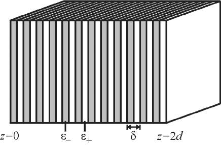
Now let us consider the layered system shown in Fig. (1), but with the gain included in the positive medium so as to exactly counter the effects of absorption in the negative medium. This can, for example, be accomplished by using a semiconductor laser material such as GaN or AlGaAs for the positive medium and silver for the negative medium. Using blue/ultra-violet (UV) light to pump the AlGaAs, (silver being transparent to the UV light), one can make the AlGaAs now optically amplifying in the red region of the spectrum, where one can satisfy the perfect lens condition for the real parts of the dielectric constant. By adjusting the pump laser intensity, the imaginary part of the positive gain medium can be tuned. The imaging can now be carried out in the red. Of course, it would be possible to use other materials and correspondingly different wavelengths of light. Alternatively one could also use other high gain processes such as Raman gain for this purpose.

We show the transmission coefficient, calculated using the transfer matrix methodbornwolf , for this layered medium with gain in Fig. (2). Our numerical calculations are exact and are not carried out in the near-field approximation. The transmission is large and comparatively flat (compared to the lossy passive case), almost up to the point () where the transmission resonances for the corresponding lossless system occurs anantha02a ; anantha02b and the transmission begins to decay exponentially. It is almost as if the effects of absorption have been cancelled out. Further, it is almost independent of the total length of the stack. However, it does not result in an exact cancellation and this can be seen from the fact that the transmission resonances of a completely lossless (and gainless) system are not restored. One can see some remnants of these resonances for the case when , and even lesser for the more absorptive (realistic for silver) case of . But it is clear that the image resolution will be improved vastly and to an almost similar extent in both cases, regardless of the levels of absorption/gain, provided the gain is large enough to compensate for the absorption. Thus with amplification included, the deleterious aspect of absorption, that it limits resolution, is cancelled out while the desirable aspect, that it softens the transmission resonances by preventing divergences, is retained. Only the transmission resonance close to is relatively undamped. In Fig. (2), the transmission across a multilayer stack of 600 nm thickness is shown (the individual layers are of 10nm thickness). We see that the transmission reduces only to 0.1 at for and an image with a resolution of about can, in principle, be transferred across the distance of the order of (the wavelength of light). Note that the resolution can be marginally larger when the small transmission tail beyond is considered. The case when a high index dielectric such as AlGaAs is used and the wavelength is tuned to match the perfect lens conditions , ( 578 nm for silver), is also shown in Fig. (2). Although it appears from the graph that the degree of sub-wavelength resolution is larger, using a large dielectric constant would give slightly lower absolute resolution as the wavelength is larger. We should also note that making the layers thinner would improve the resolution even further, and we have been quite conservative in our choice of the layer thickness.

We show in Fig. (3), the transmission as a function of the parallel wave vector and the images obtained by such layered media with optical gain. The object consists of two slits of 20 nm width which are separated by 80 nm peak-to-peak distance. In the top panel we show the images for the case when the distance between the object plane to the image plane is 80 nm. For comparision, we also show the case of the original single slab of silver as the lens (solid line and 40 nm) and a layered but gainless system. The two peaks in the image for the single slab can hardly be resolved, while they are clearly resolved in the case of the layered system with no gain. The improvement in the image resolution for the layered system with gain over the corresponding gainless systems is obvious with the sharp edges of the slits becoming visible. In the bottom panel we show the images formed by layered media with gain but with very large total thicknesses of the order of few wavelengths ( 600nm, 900nm and 1200nm). For a lossy passive system, in comparision, almost nothing would be visible at such large distances from the source. In the case of the layered system with gain, although the slits in the image are well resolved, there are extra background structures that show up in the image corresponding to the larger transmission at smaller . There is overcompensation in the lens for (subwavelength) wave vectors in the range () due to the band of transmission resonances that are relatively undamped near , and hence, the transmission function is not constant with the wave-vector. This overcompensated amplification also results in the large image intensity. We note that the effect of these resonances reduces for much larger thicknesses and the transmission function is actually more constant for thicker stacks. Although waves with very large wave vectors also get effectively amplified even for large stack thicknesses, the transmission resonances do not allow a clean image to be produced. We note, however, that since the high spatial frequency components are transferred across, knowledge of the transmission function of the lens would enable one to recover a clean image from the observed image. Alternatively, structuring the silver slabs in the transverse direction will create plasmonic bandstructures and one can engineer these band-structures to inhibit the transmission resonances close to . The transmission functions suggest that an image resolution of almost could easily be achieved with these systems.
As a note of caution, we note that in the presence of intense field enhancements that are expected in this system the gain is likely to get saturated. The largest field enhancements will be for the largest transverse wave-vectors. If we make the layers very thin, the local field enhancements will not be as intense and the gain might not get completely bleached. In general, however, we do expect that the effective gain will be somewhat reduced and the corresponding enhancements of the image resolution will be smaller. Another point of concern is that the system with gain could become unstable and undergo self-sustaining oscillations in the transverse direction due to spontaneous symmetry breaking. The layers would now just act as wave guides. This would bleach the system of all gain and the whole effect could be lost. It is clear that such effects will be minimized for a system with very thin layers. We are analyzing these effects which are beyond the scope of this paper and those results will be presented elsewhere.
In conclusion, we have shown that a multilayer stack of thin alternating layers of silver and a positive amplifying dielectric medium with optical gain/amplification can transport evanescent waves with very little attenuation even over large stack thicknesses. This novel optical fibre bundle can thus act on the evanescent near-field of a radiating source and images with high sub-wavelength resolution can be transferred across. The potential applications are immense and range from nanoscale lithography to near-field optical imaging and data storage.
Acknowledgements.
SAR would like to thank Prof. Geoff New for discussions and acknowledge the support from DoD/ONR MURI grant N00014-01-1-0803.References
- (1) J.B. Pendry, Phys. Rev. Lett. 85, 3966 (2000).
- (2) V.G. Veselago, Sov. Phys. Uspekhi, 10, 509 (1968).
- (3) S.A. Ramakrishna, J.B. Pendry, D.R. Smith, D. Schurig and S. Schultz, J. Mod. Optics (In press).
- (4) J.B. Pendry, A.J. Holden, D.J. Robbins and W.J. Steward, IEEE trans. MTT, 47, 2075 (1999).
- (5) J.B. Pendry, A.J. Holden, W.J. Stewart and I. Youngs, Phys. Rev. Lett., 76, 4773 (1996); J.B. Pendry, A.J. Holden, D.J. Robbins and W.J. Steward, J. Phys.: Condens. Matter, 10, 4785 (1998).
- (6) D.R. Smith, W.J. Padilla, D.C. Vier, S.C. Nemat-Nasser and S. Schultz, Phys. Rev. Lett., 84, 4184 (2000).
- (7) R.A. Shelby, D.R. Smith and S. Schultz, Science, 29 2, 77 (2001).
- (8) R. Ruppin, Phys. Lett. A, 277, 61 (2000); R. Ruppin, J. Phys.: Condens. Matter, 13, 1811 (2001).
- (9) P. Markos and C.M. Soukoulis, Phys. Rev. B (2002), (cond-mat/0105618).
- (10) V. Lindell, S.A. Tretyakov, K.I. Nikoskinen and S. Ilvonen , Microwave Opt. Tech. Lett. 31, 129 (2001); S.A. Tretyakov,Microwave Opt. Tech. Lett. 31, 163 ( 2001).
- (11) C. Caloz, C.-C. Chang and T. Itoh, J. Appl. Phys. 90, 5483 (2001).
- (12) E. Shamonina, V.A. Kalinin, K.H. Ringhofer and L. Solymar, Electron. Lett. 37, 1243 (2001).
- (13) Z.M. Zhang and C.J. Fu, Appl. Phys. Lett. 80, 1097 (2002).
- (14) S. O’Brien and J.B. Pendry, J. Phys.: Condens. Matter, (2002), (In Press).
- (15) D.R. Smith, D. Schurig, M. Rosenbluth, S. Schultz, S.A. Ramakrishna and J.B. Pendry, (2001) (Unpublished).
- (16) S.A. Ramakrishna, J.B. Pendry, M.C.K. Wiltshire and W.J. Stewart, J. Mod. Opt. (2002), (Submitted) .
- (17) M. Born and E. Wolf, Principles of Optics, 6th Ed. (Pergamon Press, Oxford, 1989).