Pattern Formation in Phase-Separating Gels with Spontaneous Shear
Abstract
We study pattern formation in gels undergoing simultaneous phase separation and orientational ordering. A 2D numerical simulation is performed using a minimal model of nonlinear elasticity with density-anisotropy coupling. For strong positive coupling, the collapsed phase elongates along the phase boundary and buckles, creating a folded structure with paired topological defects. For negative coupling, soft elasticity of the swollen phase causes a droplet morphology as in liquid-liquid phase separation. Their possible realizations in nematic liquid-crystalline gels are discussed.
pacs:
PACS numbers: 64.75.+g, 82.70.Gg, 83.10.Tv, 61.30.JfPolymer gels are unique objects that undergo large deformation upon phase transition, which creates various patterns. Characteristic to pattern formation in gels is the interplay between rubber-elasticity and interfacial tension, as demonstrated by the surface undulations seen in swelling/shrinking processes [1]. Elasticity also affects phase separation in bulk, which produces a foam-like morphology with the polymer-rich region connected [2, 3]. A similar morphology is observed in viscoelastic polymer solutions [4] as well as in polymerization-induced phase separation [5]. While these patterns are caused by volume phase transition of the polymer network, there is a class of amorphous solids in which transition induces shear deformation. The resulting low-temperature phase is an intermediate between usual solid and liquid, in the sense that one of the linear shear moduli vanishes in that phase [6]. We shall refer to it as “anisotropic glass” (AG) after Ref. [6]. An example of AG is provided by nematic liquid-crystalline elastomers [7, 8], which elongate along the director upon the isotropic-nematic transition. In their phase ordering process, the spontaneous shear deformation creates an anisotropic packing structure of orientationally correlated regions, which gives rise to an extremely soft nonlinear elastic response [9, 10]. The anisotropy axis of deformation is locally parallel to the nematic director, which can be integrated out to give an effective free energy as a functional of strain. The aim of this Letter is to address pattern formation in phase-separating AGs, where volume change and spontaneous shear cooperate [11]. Motivated by the idea of cell-dynamical systems [12], we adopt a minimal model of non-linear (visco-)elasticity that retains the essential features of (i) fixed-point configuration in the order-parameter space and (ii) vectorial volume-conserving dynamics.
We consider a two-dimensional system for simplicity. Let and be the positions of material element before and after deformation, respectively. The field defines the deformation tensor and a symmetric strain tensor, . For a system with rotational invariance, free energy change due to homogeneous deformations can be expressed in terms of the two invariants and , where and are the principal elongation ratios. Note that is the volume expansion ratio while gives a measure of shape anisotropy. In dimensionless units, the homogeneous part of our model free energy density is written as
| (1) |
The first term with the constants and induces density phase separation, while the coefficients , , and control shear elasticity. When and , the form of the shear free energy agrees with what prescribed by the classical affine-deformation theory of rubber-elasticity [13]. The coefficient accounts for the coupling between density and shape anisotropy, and is introduced to ensure stability when or is negative.
Because of the nonlocal nature of elastic distortion, phase coexistence in a gel crucially depends on boundary conditions and geometry, and admits no simple and exact analysis like Maxwell construction [14]. Here we restrict ourselves to the configuration of free energy minima in the plane, which helps classification of phase behavior and drawing an approximate phase diagram. For this purpose it is useful to define the effective shear modulus,
| (2) |
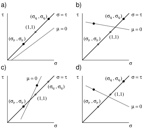
Minima of under the constraint is controlled by the location of the line with respect to the points and on the plane (Fig.1). There are four possibilities: (i) isotropic-isotropic (I-I) separation: and locate the minima if both and are positive; (ii) AG-I separation: if and , the free energy minimum corresponding to the collapsed phase is on the line and off the isotropic line ; (iii) I-AG separation (, ): the swollen phase is accompanied by spontaneous shape anisotropy; and (iv) AG-AG separation (, ).
The total free energy is the sum of homogeneous and gradient contributions, and is assumed in the form
| (3) |
While the second term penalizes density gradients and drives domain coarsening, the last term penalizes also gradients of the principal strain axis, and drives orientational ordering. To describe the latter, we define a “nematic” order parameter [6].
For the dynamics, we assume the simplest equation for gels with viscous solvents [2, 15],
| (4) |
where is the inverse of viscosity. Linearizing with respect to the displacement , we have the initial growth of the longitudinal mode as
| (5) | |||||
| (6) | |||||
| (7) | |||||
| (8) | |||||
| (9) |
while the transverse mode grows as
| (10) |
These give the spinodal conditions for density separation and orientational ordering as and , respectively.
To study the nonlinear regime, we implemented the model on a square lattice with periodic boundary conditions. The kinetic equation (4) was time-integrated with the Euler scheme. The reference parameters are , , , , , , and , with the time increment and grid size set to unity. For this set of parameters, the initial state is unstable both to phase separation and orientational ordering (as and ). For any field quantity , we shall denote its spatial averages over the collapsed () and swollen () regions by and , respectively.
Figure 2(a) shows evolution of the network density field . At an early stage, there appears a foam-like pattern connected by strands of the collapsed phase. Then the strands start to undulate. At each vertex of the foam-like pattern, the strands fold onto themselves to form a lump embracing two spots of the swollen phase. Finally the pattern coarsens in a self-similar fashion, with small vertices and thin strands dissolving. Plotted in Fig.2(b) is the distorted lattice mesh defined by (: integers), and the corresponding “Schlieren” texture . Note that each folded structure contains a pair of 1/2 defects.
To see the origin of the morphology, next we study the crossover between AG-I and I-I separation. The domain boundary becomes less wiggly as is increased, and the effective shear modulus in the collapsed phase turns positive at ; see Fig.3. For larger values of , the model reproduces the foam-like morphology known for I-I separation [2]. In the bottom of the figure, we plot versus the principal elongation ratios in the two phases. In I-I separation, the swollen phase is almost isotropic (), while the collapsed phase has a sizable strain anisotropy. This anisotropy comes from the volume mismatch between the two phases. At a flat phase boundary, continuity of the network mesh requires elongation of the collapsed region parallel to the interface, which creates elastic tension; see Fig 4(a).
In AG-I separation, on the other hand, the AG region chooses its anisotropy axis along the interface to reduce the tension. The boundary stress is completely canceled when the ratio of the spontaneous elongation matches that of the boundary-induced anisotropy. This is roughly identified with the case , which occurs at . For larger anisotropy, or when , the mismatch stress is canceled by tilting the strain axis in the AG phase, as illustrated in Fig.4(b). At boundaries between interfacial regions with different tilt directions, however, continuity of the network mesh requires a buckling of the interface. At the same time, torque is created at vertices where different strands meet, since the tilt is opposed by the clamping at the center; see Fig 4(c). This torque causes a spontaneous winding of the structure, which is further cut at two points near its center to reduce elastic free energy, creating two defects (Fig.4(d)). This leads to the patterns as seen in Fig 2.(b).
Now we consider the case of I-AG separation by assuming a negative density-anisotropy coupling. Shown in Fig.5(a) is the coarsening process for the parameters and . Initially a foam-like morphology like in I-I separation appears. As anisotropy in the AG phase develops, the cell walls break and the swollen domains merge. Finally the isotropic phase form droplets, as is the case for liquid-liquid phase separation with the same volume fraction. In Fig.5(b), we illustrate the deformation induced around an droplet of the isotropic phase. To reduce the mismatch at phase boundary, the principal elongation axis in the AG phase tends to be perpendicular to the interface. Therefore, the deformation in the AG phase is necessarily inhomogeneous.
The formation of the droplet morphology is understood from the fact that an AG in inhomogeneous deformation states is liquid-like soft [10, 16]. Internal elastic stresses are greatly reduced due to a screening of strain-mediated long-range interaction between orientationally correlated regions. In the present case, it means that stresses created at a phase boundary are not transmitted far into the AG regions. Thus, the foam-like pattern cannot be mechanically supported and the morphology is controlled by interfacial tension, leading to the liquid-like pattern.
To summarize, novel patterns should arise in phase-separating gels with density-anisotropy coupling. To realize the wiggly self-folded morphology, we need the anisotropy ratio to be in the AG phase. It is a realistic value in nematic gels made up of main-chain liquid-crystalline polymers [17]. Also, negative coupling and collapsed-isotropic–swollen-nematic separation can be achieved by using nematic solvents [18]. The 2D patterns should be observable in a film geometry as used in fabrication of polymer-dispersed liquid crystals, which basically are isotropic gels with nematic solvents and do show quasi-2D patterns [5]. It should be interesting to extend the study to a 3D system. There the swollen isotropic phase creates an isotropic tension along a flat phase boundary, while uniaxial deformation of the AG phase can cancel it only in one direction; the stress in the other direction would cause a spontaneous curvature of the boundary. On the other hand, the liquid-like morphology would be qualitatively unchanged, since the soft elasticity of the AG phase is due to the presence of bulk Goldstone modes.
I thank Professor Akira Onuki for valuable discussions.
This work is supported by
Grant-in-Aid for Scientific Research from Japan Society
for the Promotion of Science.
*Present address: Department of Physics,
Tohoku University, Sendai 980-8578, Japan.
REFERENCES
- [1] T. Tanaka et al., Nature 325, 796 (1987); E. S. Matsuo and T. Tanaka, Nature 358, 482 (1992).
- [2] K. Sekimoto et al., Phys. Rev. A 39, 4912 (1989).
- [3] A. Onuki and S. Puri, Phys. Rev. E 59, R1331 (1999).
- [4] H. Tanaka, Phys. Rev. Lett. 71, 3158 (1993).
- [5] K. Amundson et al, Phys. Rev. E 55, 1646 (1997); J. B. Nephew et al, Phys. Rev. Lett. 80, 3276 (1998).
- [6] L. Golubović and T. C. Lubensky, Phys. Rev. Lett. 63, 1082 (1989).
- [7] P. G. de Gennes, C. R. Seances Acad. Sci. B 281, 101 (1975).
- [8] H. Finkelmann et al., Makromol. Chem. Rapid Commun., 2, 317 (1981).
- [9] N. Uchida and A. Onuki, Europhys. Lett. 45, 341 (1999).
- [10] N. Uchida, Phys. Rev. E 60, R13 (1999); 62, 5119 (2000).
- [11] Spinodal fluctuation in nematic gels is already discussed by: P. D. Olmsted and S. T. Milner, Macromolecules 27, 6648 (1994).
- [12] Y. Oono and S. Puri, Phys. Rev. Lett. 58, 836 (1987).
- [13] P. J. Flory, Principles of Polymer Chemistry (Cornell University, Ithaca, 1953).
- [14] K. Sekimoto and K. Kawasaki, Physica A 154, 384 (1989).
- [15] T. Hwa and M. Kardar, Phys. Rev. Lett. 61, 106 (1989).
- [16] The liquid-like softness of an inhomogeneous AG has been reproduced by the present model (modified for a one-phase system): N. Uchida, unpublished results.
- [17] G. H. F. Bergmann et al., Macromol. Rapid Commun. 18, 353 (1997).
- [18] X. J. Wang and M. Warner, Macromol. Theory Simul. 6, 37 (1997).
![[Uncaptioned image]](/html/cond-mat/0206419/assets/x2.png)
![[Uncaptioned image]](/html/cond-mat/0206419/assets/x3.png)
![[Uncaptioned image]](/html/cond-mat/0206419/assets/x4.png)
![[Uncaptioned image]](/html/cond-mat/0206419/assets/x5.png)