Transmission Losses in Left-handed Materials
Abstract
We numerically analyze the origin of the transmission losses in left-handed structures. Our data confirms that left handed structures can have very good transmission properties, in spite of the expectable dispersion of their effective permeability and refraction index. The large permittivity of the metallic components improves the transmission. High losses, observed in recent experiments, could be explained by the absorption of the dielectric board.
PACS numbers: 41.20.Jb, 42.25.Bs, 73.20.Mf
Left-handed (LH) materials is a common name for the man-made structures which posses, in a given frequency region, both negative effective electrical permittivity and magnetic permeability. Although such materials are in general not available in nature, their experimental fabrication became possible after the suggestion of Pendry et al. [3]. They predicted, that a lattice of metallic split rings resonators (SRR) may exhibit, in a resonance frequency region, negative effective permeability . It is also well known that a periodic lattice of thin metallic wires behaves as an effective medium with negative effective permittivity [4]. By combining a lattice of metallic wires with a lattice of SRRs, Smith et al. [5] created for the first time left handed structures.
At present, LH materials attract a growing interest of both theoretical and experimental research. Various interesting physical properties of LH structures were discussed in Refs. [6] and [7]. Pendry [8] suggested that LH materials enable the construction of perfect lens. Smith et al. [9] proved, on the basis of the numerical data, that the LH structure indeed possesses negative refraction index. The negative refraction of the electro-magnetic (EM) waves was experimentally observed in Ref. [10]. These unusual results [5, 6, 7, 8, 9] have raised objections both to the interpretation of the experimental data and to the realization of negative refraction [11, 12, 13].
In spite of the considerable progress in the studies of the LH materials, a lot of questions remained unanswered. One of the most important question is, whether the LH structures have propagating solutions. LH systems must be dispersive [6]. The frequency dependence of the effective permittivity and permeability of the LH materials is [3]
| (1) |
and
| (2) |
In Eqs. 1 and 2, () is the electronic (magnetic) plasma frequency, respectively, is magnetic resonance frequency, and represents the losses of the system. Due to the strong dispersion in the resonance interval, the absorption is assumed to be large. [14] The first experiments [5, 10] indeed reported that the transmission of the LH samples was only -20 dB. Recent theoretical analysis [11] of the experimental data led even to the conclusion, that the transmission should decrease exponentially with the thickness of the LH structure. Contrary to skeptics [11] we show in the present paper that LH structures posses very high transmittance. Our recent numerical simulations [15] already showed that the transmission of a LH system could be as good as for a right-handed system.
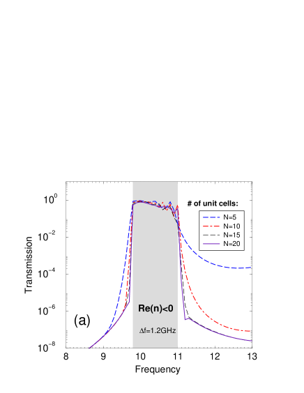
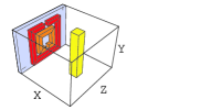
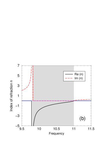
To analyze the transmission properties of LH structures in more detail, we first study the system length dependence of the transmission for the LH structure with a metallic permittivity . We will present below also the frequency dependence of for different values of . Fig. 1a shows the frequency dependence of the transmission for various system sizes. This data was obtained by the use of the transfer matrix (TM) technique [15]. The simulated structure was described in details in Ref. [15] and is shown as an inset in fig. 1a. A resonance interval of (in GHz), in which transmission is close to one, is clearly visible. Fig. 1b shows the transmission peak for a homogeneous LH model with an effective permittivity and permeability given by Eqs. 1 and 2, respectively. In Eqs. 1 and 2 we choose parameters which fit our numerical data, shown in fig. 1a. Note that the value of GHz is three order of magnitude smaller than that used in Ref. [10] to interpret the experimental data. This means that there are almost no loses in our structure. [16]
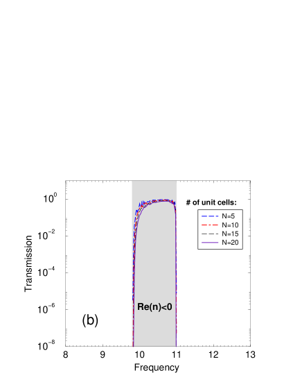
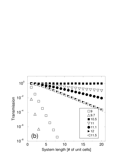
In fig. 2 we plot the transmission as a function of the system length for different frequencies . The transmission decreases exponentially with the system length, when lies outside the resonance interval. However, for EM waves with frequencies within the resonance interval only small decrease of the transmission is observed. This unambiguously shows that the transmission is really high in LH materials with realistic parameters for the permittivity of metal. This is correct despite the fact that Im is of the order of . High imaginary part of the metallic components of the LH structure does not mean that there are a lot of losses present, as it was assumed in Ref. [11].
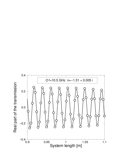
In fig. 3 we present a detailed system length dependence of the transmission for GHz, obtained by TM simulations. The length of the system was up to 300 unit cells, which corresponds to a system of length equal to 1.1 m. From the exponential decrease of the transmission amplitude we estimate the imaginary part of the refraction index to be only Im .
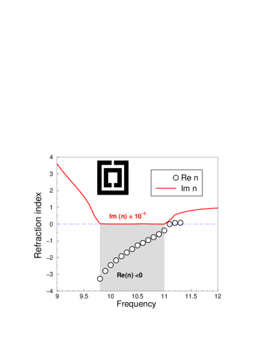
Transfer matrix data for the transmission and the reflection of EM waves provides us with the complete information needed to extract the effective parameters of the system. Inverting the equations for the transmission and reflection of the homogeneous slab of material with a given refraction index and impedance, we find the refraction index. [9] We present in fig. 4 the effective refraction index as was obtained from the numerical data. For comparison, we present also data for the refraction index, calculated from the frequency dependent and given by Eqs. 1 and 2, and . Both the numerical data and the homogeneous model give, in the resonance frequency interval, negative Re with typical resonance behavior in the vicinity of the left interval edge. We also obtain very small imaginary part for the refraction index. In particular, for the wave shown in fig. 3 we find that
| (3) |
These parameters guarantee good transmission properties.
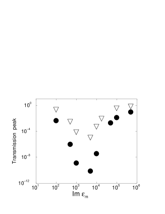
It is sometimes argued [11], that the high metallic permittivity of metallic components causes high losses in the LH structures. This is, however, not true. To show how the transmission of the LH structure depends on the permittivity of metallic components, we have simulated LH systems with Im increasing from 0 up to . As it is shown in fig. 5, an increase of the imaginary part of the metallic permittivity improves the transmission properties of LH materials, provided that Im . Although the transmission decreases to small values for Im , it starts to increase and is of the order of one for Im . As the conductance of the copper is , the imaginary part of the permittivity of copper in GHz region is of the order of . [17] We expect therefore the transmission of a realistic systems to be even better than the one displayed in fig. 5. [18] Our data clearly prove that the metallic components of the LH structures can not be responsible for the high losses observed in the experimental studies of transmission [5, 10, 19]. As the LH systems are highly dispersive [9], and still transparent, we believe that the dispersion is not the cause for the high losses in the LH structures.
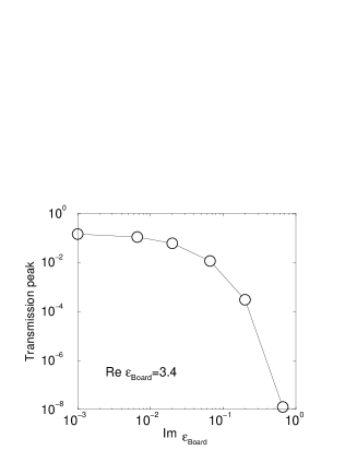
To explain the relatively low transmission, observed in the experimental data, we have studied the dependence of the transmission on other material parameters. As the most probable mechanism of losses we consider the absorption of EM waves due to nonzero imaginary part of the dielectric board, on which the metallic components are positioned. To test this hypothesis, we repeated our numerical simulations for the same structure but with a small imaginary part to the permittivity of the dielectric board: Im . Figure 6 shows how the transmission peak decreases when imaginary part of increases. Surprisingly, the transmission strongly decreases with the losses in the dielectric board.
To conclude, we presented a detailed analysis of the numerical data for the transmission of the electro-magnetic waves through left-handed structures. Recovered refraction index is in agreement with the predictions of the homogeneous model with effective parameters given by Eqs. 1 and 2. Numerical simulations confirmed the excellent transmission properties of the simulated LH systems. We found that imaginary part of the refraction index is only . As the value of the imaginary part of the metallic permittivity in real metals is even higher that that used in our simulations, we conclude that metallic components of the LH structures do not represent any source of absorption. Much higher losses were observed due to the absorption in the dielectric board on which SRRs are located.
We thank E. N. Economou for fruitful discussions. Ames Laboratory is operated for the U.S.Department of Energy by Iowa State University under Contract No. W-7405-Eng-82. This work was supported by the Director of Energy Research, Office of Basic Science, DARPA and NATO grant PST.CLG.978088. P.M. thanks Ames Laboratory for its hospitality and support and Slovak Grant Agency for partial financial support.
REFERENCES
- [1]
- [2] [*] Permanent address: Institute of Physics, Slovak Academy of Sciences, Dúbravská cesta 9, 842 28 Bratislava, Slovakia. E-mail address: markos@savba.sk
- [3] J.B. Pendry, A.J. Holden, D.J. Robbins and W.J. Stewart, IEEE Trans. on Microwave Theory and Techn. 47 2075 (1999)
- [4] D. R. Smith, S. Schultz, N. Kroll, M. Sigalas, K. M. Ho and C. M. Soukoulis, Appl. Phys. Lett. 65, 645 (1994).
- [5] D. R. Smith, W. J. Padilla, D. C. Vier, S. C. Nemat-Nasser and S. Schultz, Phys. Rev. Lett. 84, 4184 (2000); R. A. Shelby, D. R. Smith, S. C. Nemat-Nasser and S. Schultz, Appl. Phys. Lett. 78, 489 (2001)
- [6] V. G. Veselago, Sov. Phys. Usp. 10, 509 (1968).
- [7] J. B. Pendry, Phys. World 13, 27 (2000); Physics Today 53(5) 17 (2000)
- [8] J. B. Pendry, Phys. Rev. Lett. 85, 3966 (2000).
- [9] D.R. Smith, S. Schultz, P. Markoš and C.M. Soukoulis, Phys. Rev. B 65, 195103 (2002)
- [10] R. A. Shelby, D. R. Smith and S. Schultz, Science 292, 77 (2001).
- [11] N. Garcia and M. Nieto-Vesperinas, Optics Lett. (to appear in 2002)
- [12] P. M. Valanju, R. M. Walser, and A. P. Valanju, Phys. Rev. Lett. 88, 187401 (2002)
- [13] N. Garcia and M. Nieto-Vesperinas, Phys. Rev. Lett. 88, 122501 (2002)
- [14] L.D. Landau, E. M. Lifshitz and L. P. Pitaevskiĭ, Electrodynamics of Continuous Media, Pergamon Press 1984
- [15] P. Markoš and C.M. Soukoulis, Phys. Rev. E 65, 036622 (2002)
- [16] Let us note that we do not need to be very small. Even for relatively high values of there is still an appreciate amount of transmission through the LH structure (data not presented here).
- [17] J.D. Jackson: Classical Electrodynamic (3rd edition), J.Willey and Sons, 1999, p. 312
- [18] For a given metallic frequency, transmission properties depends also on the position of the SRR in the unit cell. As was shown in [15], the transmission of the LH structure with gaps of the SRR oriented along the wires is two orders of magnitude higher than that for LH structure with SRR “turned” by 90 0.
- [19] M. Bayindir, K. Aydin, E. Ozbay, P. Markoš and C.M. Soukoulis, Appl. Phys. Lett. (2002) to appear
- [20] P. Markoš and C. M. Soukoulis, unpublished.