Spin battery operated by ferromagnetic resonance
Abstract
Precessing ferromagnets are predicted to inject a spin current into adjacent conductors via Ohmic contacts, irrespective of a conductance mismatch with, for example, doped semiconductors. This opens the way to create a pure spin source (“spin battery”) by the ferromagnetic resonance. We estimate the spin current and spin bias for different material combinations.
pacs:
72.25.Mk,73.23.-b,76.50.+g,73.40.-cThe research field of magnetoelectronics or spinelectronics strives to utilize the spin degree of freedom for electronic applications. Wolf et al. (2001) Devices made from metallic layered systems displaying the giant Baibich et al. (1988) and tunnel magnetoresistance Miyazaki and Tezuka (1995) have been proven useful for read-head sensors and magnetic random-access memories. Integration of such devices with semiconductor electronics is desirable but difficult because a large resistivity mismatch between magnetic and normal materials is detrimental to spin injection.Schmidt et al. (2000) Spin injection into bulk semiconductors has been reported only in optical pump and probe experiments,Kikkawa and Awschalom (1999) and with high-resistance ferromagnetic injectors Fiederling et al. (1999) or Schottky/tunnel barriers.Monsma et al. (1998) In these cases, the injected spin-polarized carriers are hot and currents are small, however. Desirable are semiconductor devices with an efficient all-electrical cold-electron spin injection and detection via Ohmic contacts at the Fermi energy, just as has been realized by Jedema et al. for metallic devices.Jedema et al. (2001)
We introduce a concept for DC spin-current injection into arbitrary conductors through Ohmic contacts, which does not involve net charge currents. The spin source is a ferromagnetic reservoir at resonance with an rf field. Pure spin-current injection into low-density conductors should allow experimental studies of spintronic phenomena in mesoscopic, ballistic, and nanoscale systems, which up to now has been largely a playground of theoreticians like Datta and Das,Datta and Das (1990) whose spin transistor concept has stimulated much of the present interest in spintronics.
The combination of a ferromagnet at the ferromagnetic resonance (FMR) in Ohmic contact with a conductor can be interpreted as a “spin battery”, with analogies and differences with charge batteries. For example, charge-current conservation dictates that a charge battery has two poles, plus and minus. A spin battery requires only one pole, since the spin current does not need to be conserved. Furthermore, the polarity is not a binary, but a three-dimensional vector. The important parameters of a charge battery are the maximum voltage in the absence of a load, as well as the maximum charge current, which can be drawn from it. In the following we present estimates for the analogous characteristics of the spin battery.
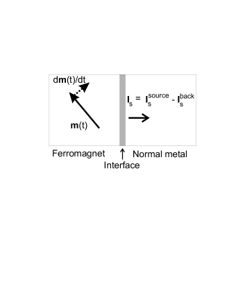
Central to our concept is a precessing ferromagnet, which acts as a source of spin angular momentum, when in contact with normal metals,Tserkovnyak et al. (2002) see Fig. 1.
This spin injection can be formulated in analogy with the adiabatic pumping of charge in mesoscopic systems. Brataas et al. (2000); Brouwer (1998) When the ferromagnet is thicker than the ferromagnetic coherence length (a few Ångstrøms in transition metals such as Co, Ni or Fe), the spin current emitted into the normal metal is determined by the mixing conductance Brataas et al. (2000) in terms of the spin-dependent reflection amplitudes between transverse modes and in the normal metal at the interface to the ferromagnet, where the latter is characterized by the magnetization direction . The mixing conductance governs the transport of spins that are noncollinear to the magnetization direction in the ferromagnet Brataas et al. (2000); Huertas-Hernando et al. (2000) and is also a material parameter proportional to the torque acting on the ferromagnet in the presence of a noncollinear spin accumulation in the normal metal.Tserkovnyak et al. (2002); Brataas et al. (2000); Xia et al. (2001a); Stiles and Zangwill (2002) For most systems (with the exception of, e.g., ferromagnetic insulators Huertas-Hernando et al. (2002)) the imaginary part of the mixing conductance can be disregarded due to the randomization of phases of spin-up and spin-down electrons in reciprocal space Xia et al. (2001a) and this is assumed in the following. The spin current emitted into the normal metal is then, simply, Tserkovnyak et al. (2002)
| (1) |
In our notation, the spin current is measured in units of mechanical torque. Eq. (1) is a time-dependent correction to the Landauer-Büttiker formula for noncollinear ferromagnetic–normal-metal (F-N) hybrid systems.Brataas et al. (2000) A simple physical picture can be inferred from the following thought experiment.Siegmann Suppose we have a F-N interface at equilibrium and switch the magnetization instantaneously. The mismatch of the spin-up and spin-down chemical potentials leads to large non-equilibrium spin currents on the length scale of the spin-diffusion length. A slower magnetization reversal naturally induces smaller spin currents. Eq. (1) represents the adiabatic limit of the spin currents pumped by a slow magnetization dynamics. When the spin current (1) is channeled off sufficiently rapidly, the corresponding loss of angular momentum increases the (Gilbert) damping of the magnetization dynamics.Tserkovnyak et al. (2002) Eq. (1) is the maximum spin current that can be drawn from the spin battery.
Next, we need the maximum spin bias obtained when the load vanishes. When the spin-flip relaxation rate is smaller than the spin-injection rate, a spin angular momentum (in units of ) builds up in the normal metal. We can neglect spatical dependence within the ferromagnet when the film is sufficiently thin.nobody Under these conditions, one finds that the component of the backflow spin current , from the normal metal to the ferromagnet, parallel to the instantenous magnetization direction is cancelled by an opposite flow from the ferromagnet. The componenent of perpendicular to isBrataas et al. (2000)
| (2) |
where is the one-spin density of states. We note that the mixing conductance in Eqs. (1) and (2) ought to be renormalized in highly transparent junctions.Gerrit E. W. Bauer and Brataas (2002)
The relation between spin excess and total spin current in a normal diffusive metal is governed by the spin-diffusion equation Johnson et al. (1988)
| (3) |
where is the diffusion coefficient, in three (two) dimensions (), and , are the elastic and spin-flip relaxation times, respectively. We solve the diffusion equation with boundary conditions at , where and at the end of the sample , where the spin current vanishes, . is the cross section of the system.
The precession of the magnetization vector of a ferromagnet under a resonant rf electromagnetic field applied perpendicularly to a DC magnetic field Slichter (1990) can be used to drive the spin battery. The magnitude of the spin current and spin bias as a function of the applied field follows from the Landau-Lifshitz-Gilbert equation where is the gyromagnetic ratio, the Gilbert damping factor, and magnetic anisotropies have been disregarded for simplicity. The spin bias also has AC components. However, its frequency harmonics are strongly suppressed when , which can be easily realized when , e.g., . is the spin-diffusion length in the normal metal. The dominant contribution to the spin bias is then constant in time and directed along . The magnitude of the time-averaged spin accumulation in the normal metal close to the F-N interface then reads:
| (4) |
where the precession cone angle between and is , is a reduction factor, and we have introduced the spin-injection rate . Large systems have a smaller injection rate since more states have to be filled.
The ratio of the injection and spin-flip relaxation times can be evaluated for a planar geometry. We consider a free-electron gas in contact with a metallic ferromagnet. The mixing conductance is () for spin injection into three-(two-)dimensional systems. First-principles band-structure calculations show that for combinations like Co/Cu or Fe/Cr remains close to unity.Xia et al. (2001a) The ratio between the injection and spin-flip relaxation times in three [two] dimensions can be calculated to be []. is the ratio of the elastic scattering rate and the spin-flip relaxation rate, which is usually much smaller than unity.
When the spin relaxation time is longer than the spin injection time and the precession cone angle is sufficiently large, , the spin bias saturates at its maximum value . In this regime the spin accumulation does not depend on the material parameters. It should be feasible to realize the full spin bias when since , e.g. when , the precession cone angle should be larger than 6 degrees. For small precession cone angles , so for e.g. T, this requires a mT rf field with a resulting spin bias of . For a smaller precession angle, e.g. degrees the spin-bias is smaller, , but still clearly measurable. Epitaxially grown clean samples with even longer spin-diffusion lengths and smaller spin-flip to non-spin flip relaxation ratios will function as spin-batteries with smaller precession angles. The precession cone angle in FMR is typically small, but 15 degrees can be achieved for a sufficiently intense rf field and a soft ferromagnet, e.g., permalloy.Heinrich The maximum DC spin current source is , e.g. for a precession cone angle of 6 degrees the equivalent electrical spin current is 0.1 nano Ampere per conducting channel . The total number of channels is a large number since the cross sections may be chosen very much larger than the Fermi wavelength thus ensuring that a large spin current may be drawn from the battery.
Ferromagnetic resonance dissipates energy proportional to the damping parameter of the magnetization dynamics. The power loss is proportional to the volume of the ferromagnet through the number of spins in the ferromagnet in units of , . The power loss can be significant even for a thin film ferromagnet, e.g., for a 10 monolayer thick Fe film with , , and s-1, the power loss per unit area is W/cm2. The temperature can be kept low by e.g. immersing the sample in superfluid helium. The heat transfer is then approximately W/cm2K for small temperature gradients and increases for larger temperature gradients,Skocpol (1974) which appears sufficient for the present purpose.
Schmidt et al. Schmidt et al. (2000) realized that efficient spin injection into semiconductors by Ohmic contacts is close to impossible with transition-metal ferromagnets since virtually all of the applied potential drops over the nonmagnetic part and is wasted for spin injection. The present mechanism does not rely on an applied bias and does not suffer from the conductance mismatch, because the smallness of the mixing conductance for a ferromagnet-semiconductor interface is compensated by the small spin current that is necessary to saturate the spin accumulation.
Possible undesirable spin precession and energy generation in the normal-metal parts of the system is of no concern for material combinations with different -factors, as, e.g., Fe () and GaAs (), or when the magnetic anisotropy modifies the resonance frequency with respect to electrons in the normal metal.
The optimal material combinations for a battery depend on the planned usage. From Eq. (1) it follows that the largest spin current can be achieved when the conductor is a normal metal, whereas any material combination appears suitable when the load is small, as long as the contact is Ohmic and the system is smaller than the spin-diffusion length.
Standard metals, like Al and Cu, are good candidate materials, since the spin-diffusion length is very long, m at low temperatures, and remains quite long at room temperature.Jedema et al. (2001, 2002) Indirect indications of spin accumulation in Cu can be deduced from the absence of any enhancement of the Gilbert damping in FMR when in contact with thin ferromagnetic films.Mizukami et al. (2001a); Tserkovnyak et al. (2002)
Semiconductors have the advantage of a larger ratio of spin bias to Fermi energy. Let us first consider the case of GaAs. The spin-flip relaxation time in GaAs can be very long, at cm3 carrier density.Kawakami et al. (2001) These favorable numbers are offset by the difficulty to form Ohmic contacts to GaAs, however. Large Schottky barrier exponentially suppress the interfaces mixing conductance parameter .
InAs has the advantage of a natural accumulation layer at the surface that avoids Schottky barriers when covered by high-density metals. However, the spin-orbit interaction in a narrow gap semiconductor like InAs is substantial, which reduces . In asymmetric confinement structures, the spin-flip relaxation rate is governed by the Rashba type spin-orbit interaction, which vanishes in symmetrical quantum wells.Nitta et al. (1997) The remaining D’yakonov-Perel scattering rate is reduced in narrow quasi-one-dimensional channels of width due to waveguide diffusion modes by a factor of , where is the spin-precession length in terms of the spin-orbit coupling ,Mal’shukov and Chao (2000) which makes InAs based systems an interesting material for a spin battery as well.
In Si, the spin-flip relaxation time is long, since spin-orbit interaction is weak. Furthermore, the possibility of heavy doping allows control of Schottky barriers. So, Si appears to be a good candidate for spin injection into semiconductors.
The spin bias can be detected noninvasively via tunnel junctions with an analyzing ferromagnet having a switchable magnetization direction. A voltage difference of is detected for parallel and anti-parallel configurations of the analyzing magnetization with respect to the spin accumulation in the normal metal, where is the relative polarization of the tunnel conductances of the contact. The test magnetic layer need not be flipped. It is sufficient to reverse the direction of the DC static magnetic field. The spin current, on the other hand, can be measured via the drop of spin bias over a known resistive element.
Spin-pumping into the normal metal can also have consequences for the nuclei via the hyperfine interaction between electrons and nuclear spins.Kawakami et al. (2001) An initially unpolarized collection of nuclear spins can be oriented by a spin-polarized electron current, which transfers angular momentum by spin-flop scattering. A ferromagnetically ordered nuclear-spin system can lead to an OverhauserOverhauser (1953) field on the electron spin. This effect does not affect the spin bias , but induces an equilibrium spin density in the normal metal via the nuclear magnetic field, and can be exploited in experiments where the the total spin-density is an important parameter. The electron-nuclear interaction can be included by adding Overhauser (1953); Slichter (1990)
| (5) |
to the electron spin dynamics so that , where is the nonequilibrium nuclear spin accumulation and is the electron-nuclear relaxation time. The nuclear spin dynamics is described by
| (6) |
where is the nuclear-spin relaxation time and is the nuclear-electron relaxation. In steady state, . In the experimentally relevant regime the electron-nuclear interaction (5) has a negligible effect on the nonequilibrium spin accumulation and thus Eq. (4) remains unchanged. for small polarizations, where is the Fermi energy of the electron gas, is the thermal energy, is the nuclear density and is the one-spin electron density.Overhauser (1953) Using ( in two dimensions) and Eq. (4) the relative enhancement of the DC nuclear spin polarization is
| (7) |
for . The nuclear-spin polarization increases with the spin bias and by lowering the temperature. The hyperpolarized nuclei, in turn, produce an effective nuclear field that polarizes the equilibrium properties of the electron gas . In bulk GaAs, the nuclear magnetic field is T when the nuclei are fully spin-polarized which should occur at sufficiently low temperatures.Paget (1977)
BergerBerger (1999) proposed to generate a DC voltage by the FMR, which bears similarities with our proposal. But Berger’s mechanism of spin injection, originating from the spin-flip scattering in the ferromagnet as induced by spin waves appears to be different from ours. We propose to achieve spin injection via the modulation of the interface scattering matrix by the coherent precession of the magnetization, which allows, for example, quantitative calculations for various materials.
In conclusion, we present the new concept of a spin battery, which is a source of spin, just as a conventional battery is a source of charge, and estimate its performance for different material combinations.
We are grateful to I. Appeli, B. Heinrich, A. D. Kent, D. Monsma, and H. C. Siegmann for stimulating discussions. This work was supported in part by the DARPA award No. MDA 972-01-1-0024, the NEDO International Joint Research Grant Program “Nano-magnetoelectronics”, FOM, the Schlumberger Foundation, and NSF Grant No. DMR 99-81283. G. E. W. B. acknowledges the hospitality of Dr. Y. Hirayama and his group at the NTT Basic Research Laboratories.
References
- Wolf et al. (2001) S. Wolf, D. D. Awschalom, R. Buhrman, J. Daughton, S. von Molnar, M. Roukes, A. Chtchelkanova, and D. Treger, Science 294, 1488 (2001).
- Baibich et al. (1988) M. Baibich, J. M. Broto, A. Fert, F. N. V. Dau, F. Petroff, P. Eitenne, G. Creuzet, A. Friederich, and J. Chazelas, Phys. Rev. Lett. 61, 2472 (1988).
- Miyazaki and Tezuka (1995) T. Miyazaki and N. Tezuka, J. Magn. Magn. Mater. 139, L231 (1995); J. S. Moodera, L. R. Kinder, T. M. Wong, and R. Meservey, Phys. Rev. Lett. 74, 3273 (1995).‘
- Schmidt et al. (2000) G. Schmidt, D. Ferrand, L. W. Molenkamp, A. T. Filip, and B. J. van Wees, Phys. Rev. B 62, R4790 (2000).
- Kikkawa and Awschalom (1999) J. M. Kikkawa and D. D. Awschalom, Nature 397, 139 (1999).
- Fiederling et al. (1999) R. Fiederling, M. Keim, G. Reuscher, W. Ossau, G. Schmidt, A. Waag, and L. W. Molenkamp, Nature 402, 787 (1999); Y. Ohno, D. K. Young, B. Beschoten, F. Matsukura, H. Ohno, and D. D. Awschalom, Nature 402, 790 (1999).
- Monsma et al. (1998) D. Monsma, R. Vlutters, and J. Lodder, Science 281, 407 (1998); H. J. Zhu, M. Ramsteiner, H. Kostial, M. Wassermeier, H.-P. Schonherr, and K. H. Ploog, Phys. Rev. Lett. 87, 016601 (2001); A. T. Hanbicki, B. T. Jonker, G. Itskos, G. Kioseoglou, and A. Petrou (2001), cond-mat/0110059; V. Motsnyi, V. Safarov, J. D. Boeck, W. v. R. J. Das, E. Goovaerts, and G. Borghs (2001), cond-mat/0110240; S. Parkin, talk at ICMFS (2002).
- Jedema et al. (2001) F. F. Jedema, A. T. Filip, and B. J. van Wees, Nature 410, 345 (2001).
- Datta and Das (1990) S. Datta and B. Das, Appl. Phys. Lett. 56, 665 (1990).
- Tserkovnyak et al. (2002) Y. Tserkovnyak, A. Brataas, and G. E. W. Bauer, Phys. Rev. Lett. 88, 117601 (2002).
- Brouwer (1998) P. W. Brouwer, Phys. Rev. B 58, R10135 (1998).
- Brataas et al. (2000) A. Brataas, Y. V. Nazarov, and G. E. W. Bauer, Phys. Rev. Lett. 84, 2481 (2000); Eur. Phys. J. B 22, 99 (2001).
- Huertas-Hernando et al. (2000) D. Huertas-Hernando, Y. V. Nazarov, A. Brataas, and G. E. W. Bauer, Phys. Rev. B 62, 5700 (2000).
- Xia et al. (2001a) K. Xia, P. J. Kelly, G. E. W. Bauer, A. Brataas, and I. Turek, Phys. Rev. B 65, 220401(R) (2002).
- Stiles and Zangwill (2002) M. D. Stiles and A. Zangwill (2002), cond-mat/0202397.
- Huertas-Hernando et al. (2002) D. Huertas-Hernando, Y. V. Nazarov, and W. Belzig, Phys. Rev. Lett. 88, 047003 (2002).
- (17) This argument is due to H. C. Siegmann.
- (18) We require that the ferromagnetic film is thinner than the spin diffusion length and , where is the exchange (stiffness) energy, is the rf frequency and is the Fermi wavelength.
- Gerrit E. W. Bauer and Brataas (2002) G. E. W. Bauer, Y. Tserkovnyak, D. Huertas-Hernando, A. Brataas (2002), cond-mat/0205453; K. M. Schep, J. B. A. N. van Hoof, P. J. Kelly, G. E. W. Bauer, and J. E. Inglesfield, Phys. Rev. B 56, 10805 (1997).
- Johnson et al. (1988) M. Johnson, R. H. Silsbee, Phys. Rev. B 37, 5312 (2000).
- Slichter (1990) C. P. Slichter, Principles of Magnetic Resonance (Springer-Verlag, NY, U.S., 1990), 3rd ed.
- (22) B. Heinrich, private communication.
- Skocpol (1974) W. J. Skocpol, M. R. Beasley, M. Tinkham, J. App. Phys. 45, 4054 (1974)
- Jedema et al. (2002) F. J. Jedema, H. B. Heershce, A. T. Filip, J. J. A. Baselmans, and B. J. van Wees, Nature (2002), in press.
- Mizukami et al. (2001a) S. Mizukami, Y. Ando, and T. Miyazaki, J. Magn. Magn. Mater. 226, 1640 (2001a); S. Mizukami, Y. Ando, and T. Miyazaki, Jpn. J. Appl. Phys. 40, 580 (2001b).
- Kawakami et al. (2001) R. K. Kawakami, Y. Kato, M. Hanson, I. Malajovich, J. M. Stephens, E. Johnston-Halperin, G. Salis, A. C. Gossard, and D. D. Awschalom, Science 294, 131 (2001); J. H. Smet, R. A. Deutschmann, F. Ertl, W. Wegscheider, G. Abstreiter, K. von Klitzing Nature 415, 281 2002; K. Hashimoto, K. Muraki, T. Saku, Y. Hirayama Phys. Rev. Lett., in press
- Nitta et al. (1997) J. Nitta, T. Akazaki, H. Takayanagi, and T. Enoki, Phys. Rev. Lett. 78, 1335 (1997); G. Engels, J. Lange, T. Schäpers, and H. Lüth, Phys. Rev. B 55, R1958 (1997).
- Mal’shukov and Chao (2000) A. G. Mal’shukov and K. A. Chao, Phys. Rev. B 61, R2413 (2000).
- Overhauser (1953) A. W. Overhauser, Phys. Rev. 92, 411 1953
- Salis (2001) G. Salis, D. T. Fuchs, J. M. Kikkawa, D. D. Awshalom, Y. Ohno, H. Ohno, Phys. Rev. Lett. 86, 2677 2001
- Paget (1977) D. Paget, G. Lampel, B. Sapoval, V. I. Safarov, Phys. Rev. 15, 5780 1977
- Berger (1999) L. Berger, Phys. Rev. B 59, 11465 (1999); J. Appl. Phys. 90, 4632 (2001).