[
Stable propagation of an ordered array of cracks during directional drying
Abstract
We study the appearance and evolution of an array of parallel cracks in a thin slab of material that is directionally dried, and show that the cracks penetrate the material uniformly if the drying front is sufficiently sharp. We also show that cracks have a tendency to become evenly spaced during the penetration. The typical distance between cracks is mainly governed by the typical distance of the pattern at the surface, and it is not modified during the penetration. Our results agree with recent experimental work, and can be extended to three dimensions to describe the properties of columnar polygonal patterns observed in some geological formations.
]
I Introduction
Cracks appearing when a material shrinks are common in everyday life. The most popular examples are probably the cracks appearing in paint layers, and those in the surface of muds. In the case of paints, there is a superficial layer of material that shrinks on top of a substrate to which it is attached. For muds, the superficial layer and the substrate are the same material, but difference in the humidity concentration produces the cracking at the surface. In these two cases, the shrinking is due to changes in the humidity concentration within the sample, but it can also be due to the existence of non-uniform temperature distributions, which produces stresses and generates cracking. The problem of surface fragmentation has been studied in the last years, both theoretically[1] and experimentally[2].
There are situations in which cracks appear at the surface of the material, and penetrate into the sample later on. A well known example corresponds to the columnar fracturing of basaltic lava, seen in many different geographical locations[3]. A detailed description of this problem has only recently been foreshadowed[4, 5], and still some points remain obscure. The two dimensional equivalent of the columnar structure of basalts corresponds to the case of a two dimensional material that dries (or cools down) starting from a free edge. As in the three dimensional case, drying creates internal stresses in the material that generate cracks, first appearing at the free edge. As the drying front propagates to the interior the cracks also do so in turn. There have been different experimental realizations of this phenomenon. In one of them[6] the material was a very thin layer of a colloidal dispersion placed between two glasses, with one free edge, from which humidity can escape. In other experiments[7], a slurry of Al2O3-water mixture was deposited onto a substrate, and a glass was placed a few millimeters above it. A low, ultra dry gas breeze was injected in the slot above the sample. The became saturated with water as it passed over the material, and a rather sharp drying front propagates with time in the same direction than the air flow. A third realization corresponds to the drying of thin films of aqueous silica sol-gel, where very nice patterns have been observed[8]. In all these cases the propagation of a set of parallel cracks has been observed.
A detailed theoretical description of this phenomenon is lacking, and we will make an attempt in this direction for the two dimensional case. In the next section we will make a general description of the phenomenon, emphasizing the difference with a more standard fracture mechanics problem. In Section III we present the calculations of elastic and crack energy for the case in which the drying (or cooling) front is sharp. In Section IV we discuss the conditions under which the crack front (formed by the tips of all cracks) is stable, and progresses into the material when the drying front advances. In Section V we show that the array of cracks generated at the surface of the material becomes evenly spaced when penetrates the sample, and that the typical width of the stripes is determined mainly during the first stage of the process, near the surface. In Section VI we briefly comment upon the effects of other drying (or cooling) conditions than the one studied previously. Section VII contains some implications of our work for the study of the three dimensional case. Finally, in Section VIII we summarize and conclude.
II Quasistatic fracture mechanics. Energetic and stress analysis
One remarkable thing about the experiments cited in the previous section [6, 7, 8] is the fact that a large number of cracks penetrate the sample in a coordinated and quasistatic manner, as the external conditions (the humidity profile) change. Then this problem is qualitatively different of a typical problem in fracture mechanics, where the propagation of a crack is usually an abrupt phenomenon and typically leads to the failure of the material. In standard fracture mechanics, stress and energetic analysis are two different ways of predicting the evolution of the fracturing process[9]. However, the equivalence of both approaches is not clear[10], particularly in cases in which the cracks propagate at large speeds, which is almost always the case when failure occurs.
The situation is different in our case. Cracks propagate only because the external humidity profile changes. If the external conditions were stationary, crack advance would be arrested. If we think on the configuration of the system as a point in configuration space (the space spanned by all coordinates of all particles of the material), at each moment the system is at one minimum of the energy landscape. As the humidity profiles changes the landscape changes itself, the minimum on which the system is located shifts, and the configuration of the system adapts so as to remain in the shifted local minimum. This is what we understand as a quasistatic propagation of cracks.[11]
Under these conditions the propagation of cracks in a two dimensional geometry can be studied by two different but equivalent procedures: Stress analysis consists on the calculation of the stress intensity factors[9] and of the opening and shearing modes at the tips of the cracks present in the system. The propagation will occur in the direction along which , which coincides with that for which is maximum. Propagation actually occurs only if the energy relieved by the advance of the cracks is enough to overcome the fracture energy needed to elongate the cracks. In the quasistatic case, these two energies will differ only infinitesimally.
In the energetic procedure to calculate crack advance, the total energy (including elastic and crack energy) after virtual advances of the cracks is calculated. Cracks will actually propagate only if this propagation reduces the total energy. Under quasistatic advance the energy reduction during propagation is infinitesimally small, and typically, there is only one possible direction of propagation for each crack, all other propagation directions would produce an increase of the total energy of the system.
Both approaches are equivalent in the case of quasistatic advance of the cracks. We will use stress analysis or energetic analysis according to convenience in each case.
III Estimations of elastic and crack energy
We will consider an isotropic and homogeneous material, and assume that linear elasticity can be applied[12]. It is well known that in this case the material possesses only two independent elastic constants[13]. We will take as these two parameters the bulk modulus and the Poisson ratio . The expansion or contraction properties of the material are described by a humidity expansion coefficient , which is formally equivalent to the thermal expansion coefficient, i.e., the relative change of linear size of a piece of material after changing the humidity concentration by some quantity is given by
| (1) |
The ideal situation we will address consists of a semi-infinite two-dimensional sample that is being dried from its surface. The drying will be considered to be non-homogeneous, and we will model it by a humidity profile that is given by some function depending on depth within the material, and time . The precise form of this function will be specified later for different experimental situations, but it is important to point out that we do not consider the case in which the appearance of cracks in the system modifies itself the drying process. Then our analysis applies more to cases as that described in [7] and possibly [8], but much less to that in [6] where evaporation of humidity through the cracks seems to be relevant(see also [14]). Although in the experimental situation the material usually lies on top of a substrate, we will study the case in which there is no interaction with this substrate. In the experiments of Ref. [7] this is achieved by introducing a layer of some slippery material between the sample and the substrate. Then, all the stresses on the sample are originated internally, and are due to the existence of a non-uniform humidity concentration.
It is known that in an isolated (namely, not clamped) piece of homogeneous material placed under a constant thermal (or humidity) gradient all stresses vanish in linear elastic approximation [15]. Under these conditions cracks cannot appear at all, or if already present from the beginning its propagation is completely halted. It is in fact crucial for the propagation of cracks that the humidity gradient it is not constant within the sample.
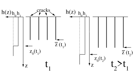
We will take the edge of the semi-infinite sample as the line, and in the interior. For convenience, we will also refer to the edge as the ‘surface’, and consider it to be horizontally placed, in such a way that the cracks propagate down the material. At the whole material is supposed to have a constant humidity concentration . In this situation the material is unstressed. Humidity concentration is assumed to decrease with time . For any reasonable experimental realization of the drying process occurring from the free surface, it is clear that at any time, well inside the material we should reach the original humidity concentration, i.e., . Then the majority of the material is always at constant humidity . In this region the sample must be unstressed, otherwise it will store an infinite amount of energy. Then a boundary condition for our problem will be that stresses go to zero as go to infinity. As a simplification of a possible experimental situation, we will consider the case of an abrupt drying profile (see Fig. 1), namely for , and for , with , and being an increasing function of time.
A given set of cracks will always correspond to a local minimum of the total energy of the system. The total energy is the sum of two well different parts. One is the fracture energy, namely, the energy spent in the creation of all fractures present in the sample. This is typically proportional to the total length of cracks in the material. The second part is the elastic energy stored in the sample. Let us suppose we have an evenly spaced array of cracks, defining stripes of width , which have penetrated down to some distance , with the drying front being located at some position .
The elastic energy stored in the material per unit of horizontal length must be proportional to the bulk modulus of the material , and to the second power of the typical change in linear density caused by the humidity gradient (this change being , with ). This is at the basis of linear elasticity theory. Using the fact that and are the only two relevant lengths for this geometrical configuration[16], dimensional analysis allows to write down the following expression for
| (2) |
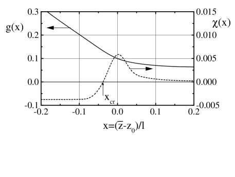
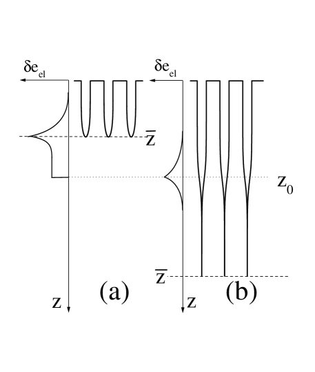
where is a dimensionless geometrical function[17]. We have determined numerically and the result is shown in Fig. 2 as a continuous line. We can rationalize the general form of the function , considering how the elastic energy is distributed along the direction. The total energy is the integral over of the density of elastic energy . In Fig. 3 we show qualitatively the form of for the cases , and . Let us consider first the case (Fig. 3(a)). is zero for , since as we already discussed, the material has to be unstressed for . In the region there is a rather constant energy density, associated to the change in humidity concentration, which cannot be compensated by a change in density of the material since the material here is attached to the part below [18]. Around the position of the crack front there is an increase of the stored elastic energy, which is associated to the elastic energy around the tips of the cracks. For the elastic energy density goes to zero, since here the existence of the cracks has allowed to relieve the elastic energy accumulated previously to the cracks formation. The linear dependence of as (i.e. for ) comes from the energy stored between and . Let us consider now the case when (Fig. 3(b)). The elastic energy becomes independent of , as the crack tips are in a region of material that is unstressed. The constant value of as comes from the energy stored in the independent stripes around the position of the humidity front, which in this limit is well behind the crack front. When there is a smooth crossover between the two limiting regimes.
To determine the actual position of the crack front in a realistic situation we will rely on the energetic argument. At any time during the drying process, the crack front will be located at the position that minimizes the total energy of the system. Equation (2) gives the elastic energy of a set of cracks that have penetrated down to the position . In order to get the total energy, has to be added to the energy cost of creating the cracks. This part, when measured per unit of horizontal length, will be called the crack energy , and it is simply given in terms of the specific energy fracture of the material in the form
| (3) |
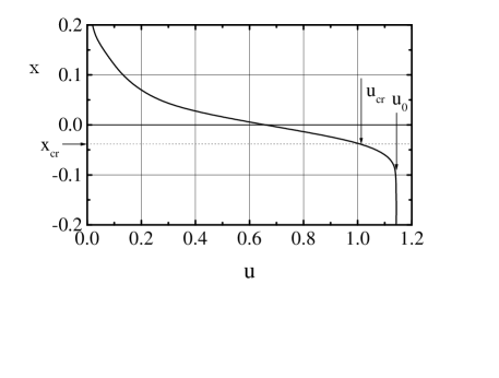
In order to determine the value of at which the fracture front prefers to be located, we have to minimize the total energy . The result we obtain is shown in Fig. 4, where we plot the most convenient position of the crack front as a function of the parameter . As we see, for very small value of , takes large and positive values, i.e., the crack front is located well below the humidity front. This is due to the negligible contribution of the crack energy compared to the elastic energy in this case. As increases decreases, crossing zero (namely, the crack front coinciding with the humidity front) at . tends to as approaches the limiting value . In fact, for the crack energy is so high that cracks do not penetrate the sample at all[19].
Under the conditions analyzed in this section, the crack front will be located at a position such that is given by the function plotted in Fig. 4. The crack front advances only due to changes in the position of the humidity front , keeping always as constant.
IV Stability of the flat crack front
The previous analysis has assumed that all cracks penetrate down to a uniform depth , and has focused on what the value of is, on energetic grounds. It has to be complemented however with a stability analysis of the crack front. The necessity of this is clear from the following example. If a material with an array of vertical cracks is loaded with a uniform horizontal stress (this situation can be thought to be realized in our case if ), there will be typically a single crack that propagates and fractures the material. This is a consequence of the fact that as soon as a single crack moves forward a small distance, the stress at its tip increases, and those at the tips of the other cracks decrease. This generates an unstable, rapid propagation of a single crack. We will see that in our case, this can be compensated by the fact that stresses decrease ahead of the humidity front, and this can stabilize a flat crack front.
The same kind of energetic arguments used in the previous section will be used to determine the stability conditions of the crack front. Consider an evenly spaced set of cracks, labelled sequentially by an index , where now the tips of the cracks are at vertical positions , which can be slightly displaced from the mean position , i.e., , with . The horizontal positions of the cracks are given by . The elastic energy of this configuration contains a term of the form (2), plus a correction that can be expanded in powers of . The first order term in this expansion vanishes, as . The second order term can be written in the form
| (4) |
Successive term contain ‘interactions’ between more distant cracks. As the elastic energy is a local quantity, we expect . Any small displacement of the crack front, defined by the quantities can be decomposed in a sum of ‘normal modes’, by going to the Fourier representation
| (5) |
and the energy decomposes into independent term, in the form
| (6) |
In order for the flat crack front to be stable, must be positive for any choice of the , and thus of the . This implies that
| (7) |
must be positive for all . In the limit of very small , is equivalent to a uniform advance of the crack front, and then is has to be a positive quantity, as the curvature of is always positive (see (2) and Fig. 2). On the other hand, It will be proportional to the sum of all coefficients in expression (7), i.e., . Then it is clear that if an instability exists for some value of , it will occur at , where . Then we will analyze the stability of the flat crack front against a perturbation with . We took the equilibrium position of a crack front obtained in the previous section (plotted in Fig. 4) and calculated numerically the quadratic change in energy when a perturbation of and amplitude is introduced. The dimensionless function can be seen in Fig. 2 (dashed line). We see that is positive (negative) for greater (lower) than . In this way we obtain that there are two regions in the plot of Fig. 4. The one at the left of corresponds to a stable situation. If the parameters of the system make the pattern of cracks to lie in that region, then the time evolution of the drying process (i.e., the increase with time of ) will produce a smooth advance of the crack front, keeping always the same value of the distance to the humidity front. At the right of , the pattern is unstable. Should we have one of those patterns at a given time, it will immediately propagate forward some of its cracks (ideally, one of each two cracks), in order to reach a stable situation. This will imply in particular that some cracks will remain halted. The further evolution of the crack front will correspond to a new crack pattern with less cracks (i.e., with larger ) being propagated.
V Appearance and ordering of cracks
Up to now we have assumed that a set of evenly spaced cracks exists, and we focused on its stability conditions. We will study now how this pattern can appear, starting with the process at the surface. Cracks are not expected to appear evenly spaced at the surface. In fact, it is known in one-dimensional models of surface fragmentation [21] (that can be used to represent the first stage of cracking of our two-dimensional problem) that the distribution of fragment length is strongly dependent on the presence of small inhomogeneities in the material, making the fragment length distribution broad. But we will see that as the superficial cracks penetrate the sample they become evenly spaced. We will first discuss how the process of nucleating new cracks at the surface is, and then argue that the cracks become evenly spaced as they penetrate the sample.
A The appearance of cracks at the surface
When the drying front penetrates the material from its surface, and before the material gets cracked, the stresses can be very simply calculated. The state of the system corresponds to the material being completely unstrained horizontally (considering the unstrained state as that corresponding to the humidity value that occurs well inside the material). Under this condition a uniform horizontal stress appears for all , which is simply calculated as . In order for the first crack to appear, this value has to overcome the uniform traction resistance of the material [22]:
| (8) |
If this relation is not satisfied, no cracks will appear whatsoever. Assuming that the relation (8) is satisfied, the first crack will nucleate at the surface. This crack penetrates the sample as long as this penetration reduces the total energy of the system. In our case, the crack penetrates only down to a distance of the order of , where the humidity front is located. The horizontal stress at the surface is now zero at the position of the crack, and increases as we move away from it, reaching the value at large distances of the crack. This means that new cracks will nucleate away of the first one, in regions where relation (8) is still satisfied. The number of cracks nucleated at the surface will be typically the minimum number that makes the horizontal stress at every point of the surface to be lower than . The typical distance between cracks can then be estimated to be[21]
| (9) |
where the geometrical function goes to infinity when , and is of order 1 for . Typically, is a few times .
If we stick to the ideal sharp drying front we have been studying, the first crack appears for an infinitesimally small value of , the only restriction is that the relation (8) is satisfied. Therefore, since the depth of the first crack is of the order of , we should expect a very dense set of superficial cracks. However, this unrealistic situation is removed if we note that any physical drying front will have some typical (finite) humidity gradient . At the moment when relation (8) is first satisfied (with being now the difference between humidity concentrations right at the surface, and well inside the material), the first crack will penetrate down to a distance
| (10) |
and the typical distance between cracks at the surface will be a few times this distance.
B How the distribution of cracks gets uniform
The cracks that appear at the surface of the sample nucleate at positions that are strongly influenced by the presence of small inhomogeneities in the sample [21]. But a superficially uneven set of cracks has a tendency to become evenly spaced as it penetrates the sample. The reason for this tendency can be understood on an energetic basis. For a fixed number of cracks the evenly spaced configuration corresponds to the minimum of elastic energy. It is then clear, using the energetic arguments, that this configuration will be approached during the propagation process[23].
It is important to clarify the different effects that inhomogeneities have on the creation and propagation of cracks. For the superficial layer, inhomogeneities are relevant, and responsible for the broad distribution of fragment lengths[21], since at the beginning all the surface is uniformly stressed, and tiny differences in the properties of the material will dictate which point of the surface will fail first. However, once the array of cracks has been defined at the surface, inhomogeneities play a secondary role, since new cracks do not appear during penetration, and the elastic energy is only very weakly dependent on the precise distribution of defects. Then the evolution of the pattern is basically the same as if inhomogeneities were absent.
The previous energetic arguments predict the trend towards evenly spaced cracks as they penetrate the sample. Stress analysis allows to re-obtain and make this result quantitative. We have calculated the stresses that are present in the semi-infinite sample with a sharp drying front, in the presence of a particular uneven set of parallel cracks. We took an infinite set of cracks separated sequentially by distances and .
For this geometrical configuration we have determined numerically the direction of maximum opening stress (mode I), at the tips of the fractures, and characterized it by its angle with respect to the direction of forward advance. The first result is that always points in the direction of making the pattern more evenly spaced. The actual value of is absolutely independent of the values of and of the material, and also on the value of the step of the humidity front. It is in fact a quantity that only depends on the Poisson ratio of the material and the values of and . The results for the angle , for a material with can be summarized as follows: is rather independent of , and within a maximum 10 % error, it can be written as
| (11) |
The value of vanishes for , as in this case the pattern is actually evenly spaced, and the cracks advance straightforwardly by symmetry. The limiting case gives deg[24]. This is the maximum bending we can expect from a given crack, in the process of uniformising the widths of the stripes. Note that as a consequence of the fact that there are no typical lengths in (11), the length needed for the pattern to become evenly spaced will be proportional to the typical width of the stripes .
Once the cracks have started to deviate in order to reduce the elastic energy as much as possible, the further detailed prediction of its evolution becomes more difficult, since now we should calculate stresses ahead of a set of non parallel fractures (or alternatively, the elastic energy of this nontrivial configurations of curved cracks). However, the main conclusion that the pattern becomes evenly spaced in a distance of the order of the stripes widths remains[26].
VI Dependences on the characteristics of the drying front
The sharp drying front is an idealization that is never exactly realized in practice. For the experiments of Ref. [7], for instance, a typical distance over which humidity changes is expected. In other cases in which the drying is through surface diffusion, the humidity profiles are still smoother. As we have already discussed the stability reason of a flat crack front in the case of a sharp humidity step is due to the rapid reduction of stresses ahead of the crack front. Smoother humidity profiles will produce a weaker tendency to generate a flat crack front, and it can even occur that a flat crack front is never stable if the humidity profile is smooth enough. In this case a pattern of bifurcations of the crack front has been predicted[27]. Note that an additional stabilizing factor of the crack front exists when the drying is favored by the presence of the cracks themselves[14], a case we have not addressed here.
VII Implications for the three dimensional case
The same phenomenon we have been discussing acquires novel characteristics in a three dimensional geometry. It has a beautiful realization in the geological formations named columnar basalts, which can be reproduced in a kitchen experiment using corn-starch[28]. When an originally hot volcanic lava flow starts to cool down (after solidification), the thermal stresses generate cracks at the surface, which propagate progressively towards the interior of the igneous body. There are many coincidences with the two dimensional case, and also some new features [3, 4, 5]. Cracks are known to appear at the surface and at later times propagate to the interior. At the surface the pattern of cracks is rather disordered, but becomes progressively ordered as it penetrates the material. In three dimensions, the tendency to order manifest in progressive tendency to form a polygonal pattern of cracks, in planes parallel to the surface. Qualitatively this tendency to order can be understood on the same basis as the two dimensional case, as a tendency of the system to reduce its total energy as much as possible during the evolution. It poses however some interesting problems, because typically, the expected perfect hexagonal pattern is not reached, but a collection of polygons with different number of sides and areas. It has been recently demonstrated[5] that this is a consequence of the fact that the patterns starts being disordered at the surface, and in the process of minimizing the energy it is not able to reach the absolute minimum (namely, the honeycomb pattern) but is trapped in a metastable minimum. Based in the arguments for the two dimensional case, we can expect also in three dimensions that the typical width of the columns is set by the typical distance between cracks at the surface, and it is not modified with the further penetration. In fact this is what is experimentally observed, since columns are seen to keep its horizontal size over distances that reach hundred times the width of the columns. For the three dimensional case, the cooling through diffusion plus convection (and/or radiation) at the surface is the most realistic model of cooling to consider. Although this type of cooling can lead in two dimensions to the instability of the flat crack front, this is not necessarily so in three dimensions, since in this case all fractures form a connected structure, and this generates an additional tendency to stabilize the flat crack front. These issues and some additional ones particular of the 3D case will be discussed in a forthcoming publication.
VIII Summary and conclusions
In this paper we have focused on a two dimensional material that cools down or dessicates from one edge. We studied the conditions under which a set of cracks penetrate the sample during the process. We showed that these cracks have a tendency to become evenly spaced, an analyze the conditions for which all the tips of the cracks form a plane front. Our results provide a quantitative framework to analyze recent experiments. Extensions to the three dimensional case are expected to provide both a qualitatively similar scenario, and also some new features that will be fully developed elsewhere.
IX Acknowledgments
This work was financially supported by CONICET (Argentina). Partial support from Fundación Antorchas is also acknowledged.
REFERENCES
- [1] T. Hornig, I. M. Sokolov, and A. Blumen, Phys. Rev. E 54, 4293 (1996); K. Leung and J. V. Andersen, Europhys. Lett. 38, 589 (1997); S. Kitsunezaki, Phys. Rev. E, 60, 6449 (1999).
- [2] A. Groisman and E. Kaplan, Europhys. Lett. 25, 415 (1994); P. Meakin, Science 252, 226 (1991); W. Korneta, S. K. Mendiratta, and J. Menteiro, Phys. Rev. E 57, 3142 (1998).
- [3] A. Holmes, Principles of Physical Geology, 3rd ed. (Wiley, New York, 1978), pp. 1–3; J. Walker, Sci. Am. 255(4), 178 (1986).
- [4] M. P. Ryan and C. G. Sammis, Geol. Soc. Am. Bull. 89, 1295 (1978); J. M. DeGraff and A. Aydin, Geol. Soc. Am. Bull. 99, 605 (1987); A. Aydin and J. M. DeGraff, Science 239, 471 (1988); P. Budkewitsch, P. Robin, J. Volcanol. Geotherm. Res. 59, 219 (1994).
- [5] E. A. Jagla and A. G. Rojo, Phys. Rev. E ?? ???? (2002).
- [6] C. Allain, and L. Limat, Phys. Rev. Lett. 74, 2981 (1995).
- [7] K. A. Shorlin, J. R. de Bruyn, M. Grahan, and S. W. Morris, Phys. Rev. E 61, 6950 (2000).
- [8] D. Hull and B. D. Caddock, J. Mat. Sci. 34, 5707 (1999).
- [9] K. B. Broberg, Cracks and Fracture, (Academic, Cambridge, 1999)
- [10] J. A. Hodgdon and J. P. Sethna, Phys. Rev. E 47, 4831 (1993).
- [11] We are implicitly assuming here that the minimum in which the system is located does not destabilizes upon a change of the external conditions.
- [12] To be more precise, we are assuming that the size of the plastic region near the tips of the cracks is always small compared to the distance between cracks. The energy dissipated in the plastic region is accounted for in the numerical value of the fracture energy defined below.
- [13] L.D. Landau and E.M. Lifshitz, Theory of Elasticity, 3rd ed. (Butterworth-Heinemann, Oxford, 1986).
- [14] T. Boeck, H.-A Bahr, S. Lampenscherfm and U. Bahr, Phys. Rev. E 59, 1408 (1999).
- [15] B. A. Boley and J. H. Weiner, Theory of thermal stresses, (Wiley, New York, 1960).
- [16] We are assuming here that , in such a way that surface effects are negligible.
- [17] To simplify the presentation we will consider a material with a fixed Poisson ratio . In a general case, all constants and functions introduced in the analysis must be considered to be also functions of .
- [18] The material is vertically compressed in this region in such a way that vertical stress vanishes. However, it is the impossibility of producing a horizontal compression what generates a horizontal stress and then the finite value of this part of the elastic energy.
- [19] From the results of Fig. 4 we can obtain the result that thiner stripes will have their crack front more retracted compared to thicker stripes (since ), and that a minimum is necessary for propagation. This is qualitatively comparable to experimental results [20] showing that a single crack propagating in a glass plate of width between two thermal baths has an equilibrium position that retracts as reduces, and also that the propagation is halted if is lower than some critical value.
- [20] O. Ronsin, and B. Perrin, Phys. Rev E 58, 7878 (1998).
- [21] O. Morgenstern, I. M. Sokolov, and A. Blumen, Europhys. Lett. 22, 487 (1993); J. Phys. A 26, 4521 (1993).
- [22] This is the traction resistance value for the bulk material, which of course takes into account the existence of defects (such as microcracks) in the material.
- [23] The tendency to uniformise the stripe width is also consistent with the experimentally observed stability of a crack propagating exactly at the middle of a glass plate, driven by a temperature difference (see Ref. [20]).
- [24] This value nicely coincides with the expected half angle for the infinitesimal branching of an original straight crack under mode I loading, see Refs. [9] and [25].
- [25] M. Isida and H. Noguchi, Int. J. Fract. 54, 293 (1992).
- [26] During the process of uniformising an originally disordered set of cracks, the crack front can deviate slightly from the sharp form expected for evenly spaced cracks. For instance, for a set of fractures with a typical width of columns that depends smoothly on the horizontal coordinate, the fracture front will be forwardly advanced at those position with largest , and retracted at positions with smallest .
- [27] H.-A Bahr, U. Bahr, and A. Petzold, Europhys. Lett. 19, 485 (1992).
- [28] G. Müller, J. Geophys. Res. 103, 15239 (1998).