Diffraction in left-handed materials and theory of Veselago lens
Abstract
A theory of diffraction in the system consisting of the left-handed and the right-handed materials is proposed. The theory is based upon the Huygens’s principle and the Kirchhoff’s integral and it is valid if the wavelength is smaller than any relevant length of the system. The theory is applied to the calculation of the smearing of the foci of the Veselago lens due to the finite wavelength. We show that the Veselago lens is a unique optical instrument for the 3D imaging, but it is not a “superlens” as it has been claimed recently.
In his seminal work Veselago [1] has introduced the concept of the left-handed materials (LHM’s). In a simplest case the LHM’s are materials with simultaneously negative electric permittivity and magnetic permeability in some frequency range. It is easy to show that in the LHM the vectors form a left-handed set, while in the usual materials (, ) they form a right-handed set. If imaginary parts of and are small, the electromagnetic waves (EMW’s) propagate in the LHM but they have some unusual properties. All these properties originate from the fact that in the isotropic LHM the Poynting vector is anti-parallel to the wave vector .
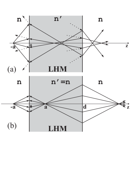
Consider a propagation of the EMW from a point source located at the point through an infinite slab of the LHM with the thickness and a usual right-handed material (RHM) at and (Fig.1). It is obvious that everywhere at because the energy propagates from its source. The directions of vector for different rays are shown by arrows. They should be chosen in such a way that at both interfaces tangential components of vector for incident, reflected and refracted waves are the same. Another condition is that the component should be parallel to in the RHM and anti-parallel in the LHM. Then in the LHM is negative. It follows that the Snell’s law for the RHM-LHM interfaces has an anomalous form: , where and are the angles of incidence and refraction respectively, and are positive refractive indexes for LHM and RHM respectively. The angles of reflection are equal to the angles of incidence. The refractive index in the LHM is often defined as negative[2], but we avoid this definition because in an infinite medium an EMW may propagate in any direction in both LHM and RHM and the only physical difference is that vector is directed from the source of the wave in the RHM, while in the LHM it is directed toward the source.
The device shown at Fig.1(b) is a unique optical lens proposed by Veselago. In this lens and , then and . It is easy to show that at the reflected wave is completely absent. Since all the rays going right from the source have , all of them have foci at points and as shown in Fig.1(b).
All the ideas above have been put forward by Veselago about years ago[1]. Recently the method of fabricating of the LHM’s on the basis of metallic photonic crystals has been found and the San Diego group has reported the first observation of the anomalous transmission [3] and even the anomalous Snell’s law [2]. Both observations have been interpreted as the result of negative and . The speculations about the nature of negative and in photonic crystals are still controversial (compare [2, 3, 4, 5, 6]), but the very existence of the LHM seems to be demonstrated. Since the LHM’s become reality it is time to develop a deeper understanding of their electrodynamic properties in order to use the advantages of these materials.
One can see that the Veselago lens, shown at Fig.1(b), is an absolute instrument because it images stigmatically a three-dimensional domain and the optical length of any curve in the object space is equal to the optical length of its image[7]. The only other absolute instrument we are aware of is the famous “fish-eye” of Maxwell [7]. Note, that the definition of the absolute instrument assumes geometrical optics only. Since the LHM’s have been already obtained we think that the Veselago lens can be extremely important device for the 3D imaging.
Pendry [4] claims that the Veselago lens has a different unique property. Due to Pendry the resolution of this lens does not have a traditional wavelength limitation which follows from the uncertainty principle. Pendry has introduced a new term “superlenses” with the Veselago lens as a first representative of this class. Two comments appeared recently [9, 10] where the work of Pendry was criticized.
In this paper we propose a general scalar theory of diffraction in the LHM which is based upon the Huygens’s principle and the Kirchhoff’s integral. As any diffraction approach our theory works under condition that the wavelength is much smaller than any relevant geometrical length in the problem. We apply this theory to the Veselago lens and calculate the smearing of the foci due to the finite wavelength. Thus, our result does not support the idea of “superlens”. The discrepancy between our result and previous ones is analyzed.
The first problem is to find the Green function for the Helmholtz equation for the LHM which describes propagation of a spherical wave from the point source. It is easy to show that it has a form , where and is a distance from the source. At a small element of the sphere the spherical wave can be considered as a plane wave which is characterized by the Poynting vector and wave vector both with the radial component only. Since is directed along the external normal to the surface element, the wave vector in the LHM is directed along the internal normal. It is easy to see that our Green function obeys these properties.
Following the principles of the scalar theory of diffraction[8] the field at the observation point can be written in a form of a surface integral
| (1) |
where is the length of the vector from the point to the surface element, is the projection of the surface element on the plane perpendicular to the direction of the ray coming from the source to , is a constant for any LHM. To find one can consider a plane wave with the wave vector normal to the infinite plane of integration. Since this plane is fictional, the constant can be found from the condition that the Huygens’s principle in the form Eq.(1) reproduces the same plane wave. Doing the calculations similar to Ref.[8] one gets , so that for the LHM the constant has a different sign than the similar constant for the RHM.
The Huygens’s principle can be applied to any interface which has a curvature larger than the wavelength. It gives the correct direction of refracted waves but it does not give the amplitudes of both refracted and reflected waves. However, it can be successfully applied to the Veselago lens where reflected waves are absent.
Note, that there are some other methods to describe the diffraction which may be also used if the source of the rays is unknown. They are described and compared in details in Jackson’s textbook [11]. One can show that all the methods give the same result at .
Now we apply Eq.(1) to the Veselago lens. To find the field inside the slab we shall integrate in Eq.(1) over the plane . The field in this plane is produced by a point source and has a form
| (2) |
The field inside the slab can be found using Eq.(1) with a constant instead of because now we are integrating over the RHM-LHM interface rather than over the fictional surface in the LHM. In a similar way at the LHM-RHM interface one should use a constant . Using the method described in Ref.[8] it is easy to show that and . Thus one gets
| (3) |
where the additional factor is the cosine of the angle between the ray, coming from the source to the point and the unit vector in direction. One can see that the optical lengths for all rays (the sum of exponents in the integrand of Eq.(3)) from the point source to the focus, located at , , are zero and the value of the field at the focal point , while the geometrical optics gives an infinite field in this point. To find in the vicinity of the focus one should expand the integrand in Eq.(3) near the point assuming , and , where . One gets
| (4) |
where . At one gets analytical expression
| (5) |
Another analytical expression can be obtained at
| (6) |
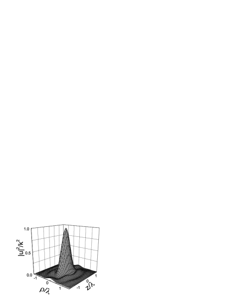
Figure 2 shows dimensionless function as given by Eq.(4). One can see that the smearing of the focus is anisotropic. The half-width in direction is approximately one wavelength while in direction it is approximately twice as less. At small the surfaces of a constant are ellipsoids of revolution along axis.
Now we find the field in the close vicinity of the second focus located at , . The general expression for at differs from Eq.(3). One should apply the Huygens’s principle to both interfaces located at and . The later one is the LHM-RHM interface and the constant should be used instead of . One gets an additional integral over the plane so that expression for the field has a form
| (7) |
To calculate these integrals in the vicinity of the second focus using inequalities , one should introduce new variables instead of variables by relations
| (8) | |||
| (9) |
Equation (8) has the following meaning at . For every point at the first interface they give a point at the second interface which is on the ray coming from and passing through the first focus. Thus the new variables describe deviation from the geometrical optics and they should be small. One can see from Eq.(7) that at optical lengths of all rays exiting from the point source at and coming to the second focus at are equal to zero. Introducing the new variables and expanding the exponents in Eq.(7) one can get an expression for the field in the vicinity of the second focus. For , one gets
| (10) |
where the function is given by Eq.(3). In other words, the smearing of the in the second focus is the same as the smearing in the first one.
Equation (10) can be also obtained in a more physical way. One can calculate field far from the foci expanding integrand in Eqs.(3,7) near the geometrical rays as it was described above. In this case the result is exactly the same as in the geometrical optics. Namely, in the region
| (11) |
where , . At one should substitute into Eq.(11) , . The expression in Eq.(11) becomes infinite in both foci as it should be in the framework of the geometrical optics. However, it can be used to calculate field at the plane
| (12) |
Note that the minus sign in Eq.(12) results from the passing of the rays through the first focus. This gives extra phase .
Now we can forget about the region and apply the Huygens’s principle to the to find the field near the second focus. The field will be described by Eq.(1) with the positive exponent and . Finally we get the result which is connected with Eq.(3) by Eq.(10).
Using Eq.(11) one can calculate the flux of energy through any plane perpendicular to axis for . One can show that it is independent on and equal to in our units. Note, that the flux of energy through the hemisphere around the point source at defined as is equal 2, since .
Now we compare our results with the analytical calculations of Pendry [4] and Ziolkowski and Heyman [12]. Both papers claim that the Veselago lens in the ideal (lossless) regime is a “superlens”, which is able to provide a perfect focusing. In both papers the spherical wave outgoing from the source is represented as a superposition of plane waves, which are fictitious and do not correspond to the cylindrical symmetry of the problem. This superposition contains the “evanescent” waves (EW’s), for which . One can easily show that the Poynting vector of each EW has a non zero components in the - plane but zero component in direction. It follows from the second observation that the contribution of the EW’s to the intensity near the foci of the Veselago lens should be exponentially small if . Pendry has explained perfect focusing as a result of amplification of EW’s by the LHM.
One can see from Eq.(47a) of Ref.[12] that the amplitude of a single EW increases exponentially in the LHM with increasing distance from the source. Since the LHM is a passive medium, we think, that these EW-solutions should be omitted as nonphysical. The mathematical inconsistency of these solutions can be seen from the fact that the integral (Eq.(38) of Ref.[12]), that describes the superposition of the plane waves, diverges at large in the interval at any value of and . Note, that the contribution of propagating waves into this integral is finite and it coincides with our result near the foci.
The advantage of the diffraction theory is that it is a regular perturbation with respect to . We think that the EW’s never appear in this theory because their contribution is of the order of .
The computations, performed in Ref.[12], do not show any focusing. We think that the main reason is that their and are of the order of the wavelength. Our calculations do not predict any focusing for such wavelength.
Finally, we have proposed the theory of diffraction in a system, consisting of the LHM and the RHM and have applied this theory to the calculation of the smearing of the foci of the Veselago lens. This smearing is of the order of the wavelength so, from this point of view, the Veselago lens does not differ from any other lens.
The work has been funded by the NSF grant DMR-0102964.
REFERENCES
- [1] V. G. Veselago, Sov. Phys.-Solid State 8, 2854 (1967); Sov. Phys. Uspekhi 10, 509 (1968).
- [2] R. A. Shelby, D. R. Smith, and S. Schultz, Science 292, 77 (2001).
- [3] D. R. Smith et al., Phys. Rev. Lett. 84, 4184 (2000).
- [4] J. B. Pendry, Phys. Rev. Lett. 85, 3966 (2000).
- [5] P. Marcos and C. M. Soukoulis, Phys. Rev. B 65, 033401 (2001).
- [6] A. L. Pokrovsky, A. L. Efros, cond-mat/0112461.
- [7] M. Born and E. Wolf, Principle of optics (Pergamon Press, Oxford, 1980), p. 143.
- [8] L. D. Landau, E. M. Lifshitz, The classical theory of fields (Butterworth Heinemann, Oxford, 2000), p. 156.
- [9] G. W. ’t Hooft, Phys. Rev. Lett. 87, 249701 (2001).
- [10] J. M. Williams, Phys. Rev. Lett. 87, 249703 (2001).
- [11] J. D. Jackson, Classical Electrodynamics (Willey & Sons, New York, 1998), p. 478.
- [12] R. W. Ziolkowski and E. Heyman, Phys. Rev. E 64, 056625 (2001).