Spin-polarized tunneling in ferromagnetic double barrier junctions
Abstract
Spin-polarized tunneling in FMS/M/FMS double tunnel junctions where FMSs are ferromagnetic semiconductor layers and M is a metal spacer is studied theoretically within the single-site coherent potential approximation (CPA). The exchange interaction between a conduction electron and localized moment of the magnetic ion is treated in the framework of the s-f model. The spin polarization in the FMS layers is observed to oscillates as a function of the number of atomic planes in the spacer layer. Amplitude of these oscillations decreases with increasing the exchange interaction in FMS layers.
PACS. 72.25.-b Spin polarized transport - 75.50.Pp Magnetic semiconductors - 75.70.Ak Magnetic properties of monolayers and thin films
I Introduction
There is much recent interest in the spin-polarized transport in multilayers of ferromagnets and paramagnets. These include the giant magnetoresistance, spin-injection experiments, and spin-polarized tunneling experiments which have application potential in digital storage and magnetic sensor technologies [1, 2]. The spin-polarized tunneling phenomenon, showed that spin is conserved in the tunneling process and the electrons coming from a ferromagnet are spin-polarized [3]. In the last decade, with the progress in the research on magnetic multilayers, spin-polarized tunneling through magnetic semiconductor (MS) layers has received increasing attention [4, 5, 6]. In tunneling experiments, when a FMS is used as a tunnel barrier, the conduction band splits into up spin and down spin subbands and the barrier height for these two subbands is changed. Because of this exchange splitting, the probability of tunneling for up spin electrons increases but for down spin it decreases. Using MSs tunnel barriers such as EuS or EuSe, one can obtain nearly 99% spin-polarized tunneling electrons even with nonmagnetic electrodes [7, 8].
The purpose of this paper is to study the spin polarization of the tunneling density of states in FMS double barrier junctions, and show that it oscillates with the spacer thickness. The single-site CPA for the s-f model in completely ferromagnetic case is used in the calculations [9]. In order to determine the oscillations, we estimate the difference in tunneling spin polarization between the FMS single barrier and double barriers.
Although the CPA and the corresponding Alloy Analogy are not the best starting points for treating the spin-polarization of conduction electrons, we believe that the technique outlined in this article can qualitatively recover the expected behavior for the spin polarization as a function of the exchange coupling, the doping, and the spacer thickness.
II Model and formalism
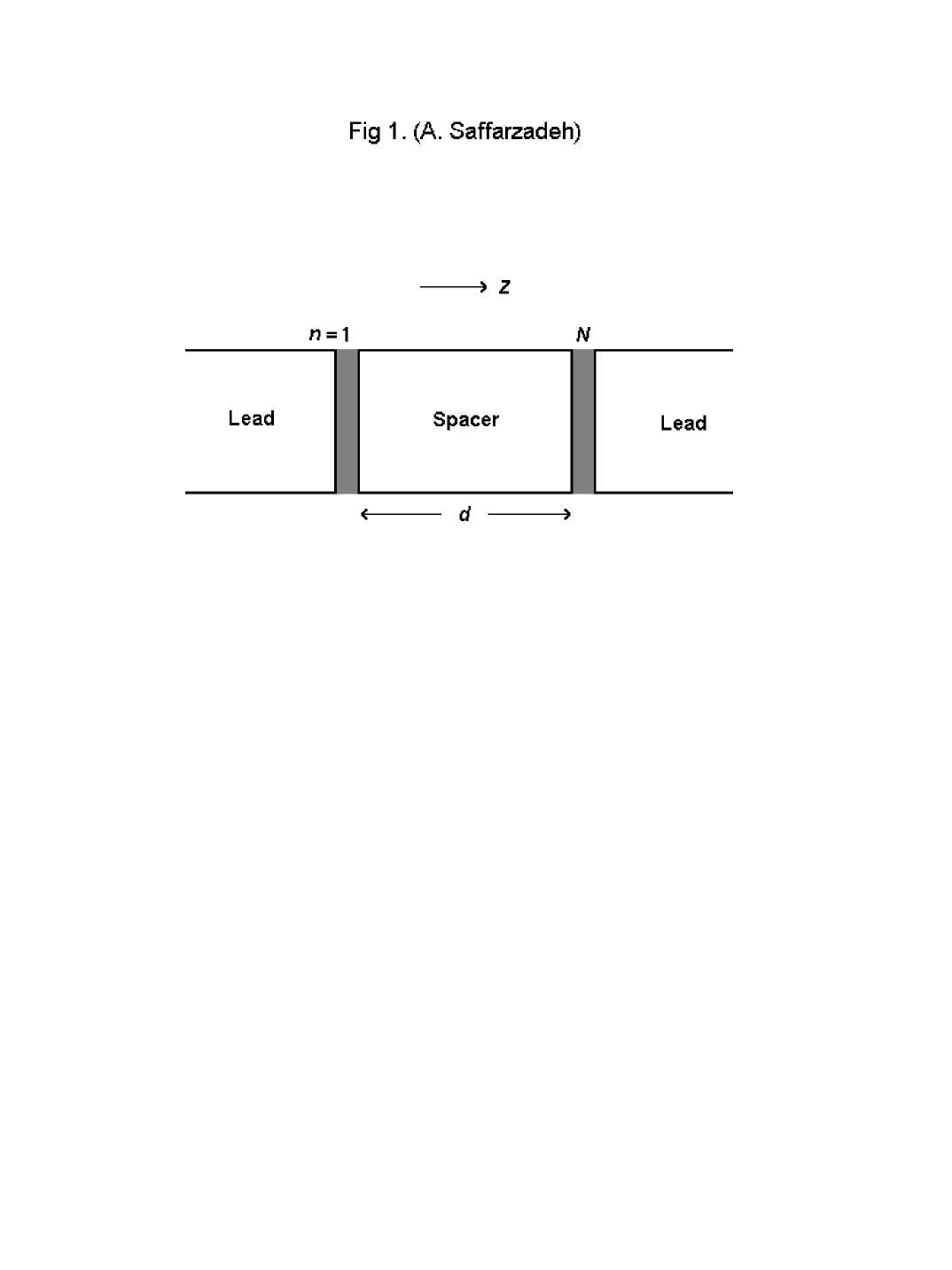
We consider a trilayer consisting of two FMS monolayers separated by a nonmagnetic spacer. The trilayer is sandwiched between two semi-infinite ideal lead wires as shown in figure 1. We assume that the interfaces between the FMS layers and the spacer are sharp. Both the trilayer and lead wires described by a single-orbital tight-binding Hamiltonian with nearest-neighbor hopping on a simple cubic lattice with lattice constant . We choose the (001) axis of the simple cubic structure to be normal to the layers and this direction is called -direction hereafter.
We use the s-f (or s-d) model which is commonly considered as realistic for local-moment semiconductors and metals. In this model the following Hamiltonian is used to describe the present system:
| (1) |
| (2) |
| (3) |
| (4) |
where and denote the position in - plane and the layer index in the -direction, respectively. Here is the transfer energy of an s-electron with spin between nearest-neighbor sites. Each lattice point of the FMS layers is occupied by a localized magnetic moment, represented by a spin operator . describes the Heisenberg-type exchange interaction between these localized moments where is an exchange integral. is the s-f exchange interaction between the s-electron and the f-spin where is the Pauli matrix for the conduction electron spin, and is the s-f exchange coupling constant. In and , is the position of the FMS layers in the -direction. It is assumed that the localized moments of the magnetic ions in two FMS layers to be the same magnetic moment. The metal spacer is consisting of atomic layers which describes by .
In ordinary magnetic semiconductors, the magnetic excitation energy may be smaller by two to three orders of magnitude than other typical energies, as the Bloch bandwidth or the s-f exchange interaction energy ; thus, the f-spin is treated as a static system. On the other hand, due to the Mermin-Wagner theorem [10, 11], an effectively two-dimensional spin-isotropic system cannot display long-range magnetic order at finite temperatures, 0 K [12]. This is one important reason why anisotropies play a fundamental role for the understanding of thermodynamic phase transitions in thin films. This restriction however, does not suppress the main physical aspects at =0 K. The spin splitting in density of states of tunneling electrons is the main origin of the electron-spin polarization, and is independent of the FMS layers thickness [13]. Thus we do not inspect how the spin system is affected by the reduced translational symmetry.
The CPA [14] was originally thought as an approximate theoretical treatment of statistically disordered systems, e.g., binary alloys, but it can easily be generalized to a random spin system if we ignore correlated motion of localized spins [15]. In this investigation we use the CPA for the s-f model in a single-site -matrix formula, according to Ref.[9].
When an s-electron is propagating in the FMS layers it will subject to different effective potentials through the s-f exchange interaction according to the orientation of its spin. In order to treat the exchange scattering of the s-electron within the framework of the single-site CPA, we consider a single f-spin located at site r in an effective layered medium where an s-electron is subjected to a complex potential (or coherent potential) which is site diagonal and takes the value or , according to the spin orientation of the s-electron [6]. Therein, an s-electron moving in this effective medium can be described by the effective Hamiltonian in the Bloch-Wannier representation as
| (5) |
where is the layer- and spin-dependent coherent potential which is only non-zero in the FMS layers. Here, is a wave vector parallel to the layers.
As in Refs. [6, 9], we apply the condition that the average scattering of the s-electron by the single f-spin in the medium is zero. Thus we define the single-site -matrix of the s-f exchange interaction as
| (6) |
where is the effective Green’s function defined by
| (7) |
Here is the complete scattering associated with the isolated potential in the th effective layer (=1 and ), which is expressed as
| (8) |
Within the single-site CPA, the condition
| (9) |
for any in the FMS layers, leads to the equations for in Ref.[9]) and in Ref.[9]). Here the bracket means the thermal average.
In the completely ferromagnetic case (i.e. =0 K) the orientations of the f-spins are perfectly arranged in one direction (-direction). In this case the coherent potentials for two spin-polarized subbands are expressed in the following simple forms [9]:
| (10) |
| (11) |
with
| (12) |
Here, is the Green’s function of the th layer, is the number of lattice sites in each layer and , where is a small positive number. Using the Eqs. (5) and (7), the Dyson equation in the Bloch-Wannier representation can be written as
| (13) |
where
| (14) |
| (15) |
and the unperturbed Green’s function is given by
| (16) |
Here,
| (17) |
| (18) |
In Eqs. (13)-(15), we have suppressed the variables and for simplicity. We have solved these equations numerically for . From equation (12) we can calculate the local density of states (LDOS) per atomic site for spin electron in the effective layer as
| (19) |
which should satisfy the following equation in all of the present numerical calculations
| (20) |
In order to study the tunneling spin polarization, we assume that is equal to , where is the number of electrons with up (down) spin after tunneling to the FMS conduction band, is the LDOS with up (down) spin at the th layer, and is a typical energy of the tunneling electrons. Thus the magnitude of the spin polarization for tunneling density of states in each layer can be given by [6, 16]
| (21) |
where is the Fermi energy, because it is expected that only electrons near the Fermi level participate in tunneling process.
We are mainly interested in the difference between the electron-spin polarization in FMS/M/FMS and M/FMS/M junctions. Hence, in the present results an effective polarization is used in place of which is defined as
| (22) |
where and are the layer dependence of spin polarization () in M/FMS/M and FMS/M/FMS junctions respectively. In fact we are interested in studying that part of the electron-spin polarization which is due to the existence of the second FMS barrier (at ); thus, it is convenient to cancel the contribution of M/FMS/M junction to the spin polarization. In this way it is reasonable to discuss the effective polarization. Note that in the M/FMS/M structure the FMS layer is at .
III Numerical results
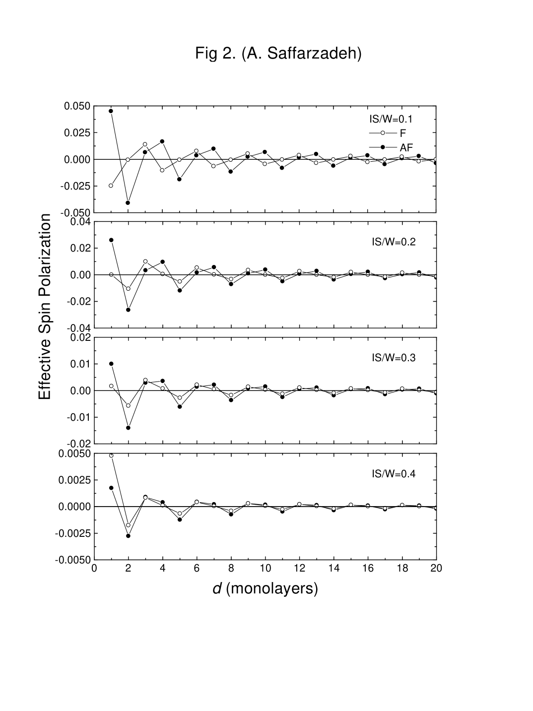
In the numerical calculations the energy is measured in units of and the small imaginary part of the energy is chosen =0.02 to simplify the calculations. The numerical results for the spin polarization in FMS layers as a function of the spacer layer thickness are shown in figure 2 for two cases: the localized moments in two FMS layers aline in ferromagnetic (F) configuration () and the moments aline in antiferromagnetic (AF) configuration (). These results are shown for various values at . Here which is the exchange-interaction strength, describes formally the strength of the scattering processes in the ferromagnetic barriers.
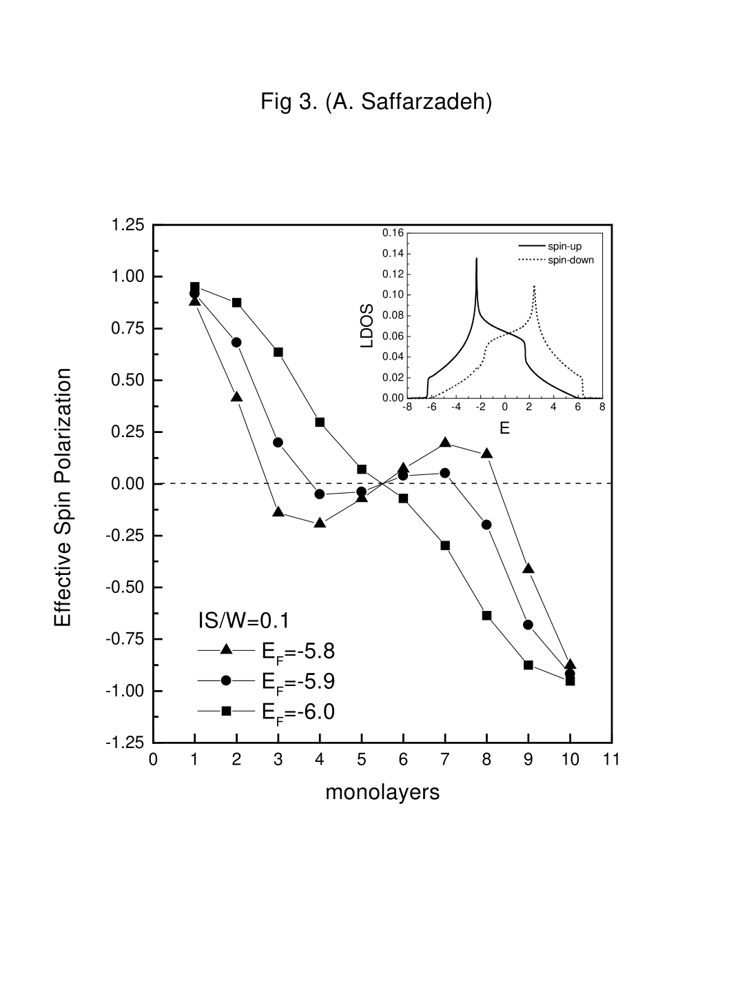
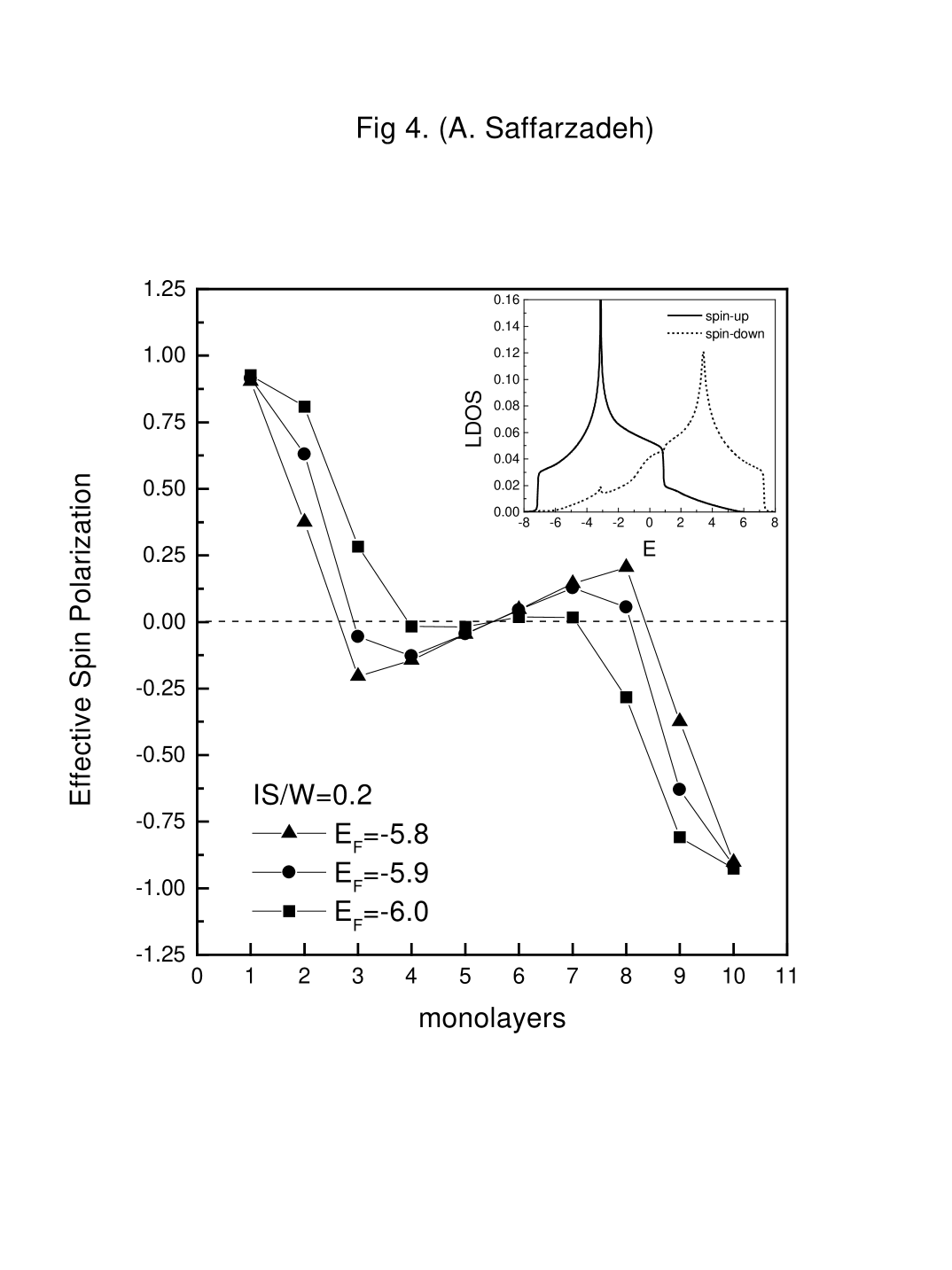
This figure shows that the effective spin polarization in FMS layers oscillates by increasing the spacer thickness. The physical origin of such oscillations is attributed to quantum interferences due to spin-dependent reflections of the electrons at the FMS/M interfaces. The multiple interferences that take place in the spacer, induce a change in the density of states of each subband. Clearly, if the interferences in the spacer are constructive, one has an increase of the density of states; conversely, when the interferences are destructive, the density of states decreases. For the AF alignment, where the magnetizations of the right and left FMS layers are anti-parallel, electrons with up (down) spin are easy (difficult) to tunnel into the spacer, and difficult (easy) to tunnel out of it, because the densities of states of the left and right FMS layers are different between up and down spin subbands (the inset of figure 3 and 4). This imbalance among the tunnel currents causes the spin accumulation, when the spin-relaxation time is sufficiently long in the spacer. By increasing the , the band of up (down) spin is shifted to the low (high) energy side and the splitting between these subbands is increased [16]. In this case the is increased and the multiple interferences in the spacer and the difference between the and the is reduced. Thus, by fixing the for different values of , the amplitude of oscillations of the effective spin polarization is decreased.
The effective spin polarization inside the spacer is shown in figures 3 and 4 for the AF alignment. Here the spacer is consisting of eight atomic layers. As the figures show, by decreasing the Fermi energy, the effective spin polarization in the spacer decreases. It confirms that because of the increase in spin splitting between up spin and down spin subbands, the effect of multiple interferences in the spacer and therefore the amplitude of oscillations are reduced. Using these results, one can see that how long the spin-polarized electrons remember their spin orientation. This is especially important for electronic applications, because if the spins relax too rapidly, the distances traversed by the spin-polarized current in a device will be too short to serve any practical purpose.
IV Concluding remarks
To summarize, on the basis of the single-site CPA for the s-f model at =0 K, we have investigated the spacer thickness dependence of the tunneling spin polarization in FMS/M/FMS double tunnel junctions. We have found that the spin polarization in the FMS layers oscillates as a function of their separation. These oscillations is shown to decreases with increasing the . This approach will be improved by taking electron-magnon scattering into account, which plays essential roles at low temperatures. The present formulation is applicable to problems of the interlayer exchange coupling and the tunneling conductance in FMSs.
REFERENCES
- [1] J.S. Moodera, L.R. Kinder, T.M. Wong, R. Meservey, Phys. Rev. Lett. 74, 3273 (1995).
- [2] J. Daughton, J. Appl. Phys. 81, 3758 (1997).
- [3] R. Meservey, P.M. Tedrow, Phys. Rep. 238, 174 (1994).
- [4] R. Metzke, W. Nolting, Phys. Rev. B 58, 8579 (1998).
- [5] A.S. Borukhovich, Phys. Usp. 42, 653 (1999).
- [6] A. Saffarzadeh, Phys. Lett. A 270, 353 (2000).
- [7] J.S. Moodera, X. Hao, G.A. Gibson, R. Meservey, Phys. Rev. Lett. 61, 637 (1988).
- [8] J.S. Moodera, R. Meservey, X. Hao, Phys. Rev. Lett. 70, 853 (1993).
- [9] M. Takahashi, K. Mitsui, Phys. Rev. B 54, 11298 (1996).
- [10] N. D. Mermin, H. wagner, Phys. Rev. Lett. 17, 1133 (1966).
- [11] A. Gelfert, W. Nolting, Phys. Stat. Sol. (b) 217, 805 (2000).
- [12] R. Schiller, W. Nolting, Solid State Commun. 110, 121 (1999).
- [13] R. Schiller, W. Müller, W. Nolting, J. Magn. Magn. Mater. 169, 39 (1997).
- [14] P. Soven, Phys. Rev. 156, 809 (1967).
- [15] A. Rangette, A. Yanase, J. Kübler, Solid State Commun. 12, 171 (1973); K. Kubo, J. Phys. Soc. Japan 36, 32 (1974)
- [16] M. Takahashi, Phys. Rev. B 56, 7389 (1997).