Exchange Bias in Ferromagnetic/Compensated Antiferromagnetic Bilayers
Abstract
By means of micromagnetic spin dynamics calculations, a quantitative calculation is carried out to explore the mechanism of exchange bias (EB) in ferromagnetic (FM)/compensated antiferromagnetic (AFM) bilayers. The antiferromagnets with low and high Néel temperatures have been both considered, and the crossover from negative to positive EB is found only in the case with low Néel temperature. We propose that the mechanism of EB in FM/compensated AFM bilayers is due to the symmetry broken of AFM that yields some net ferromagnetic components.
pacs:
75.70Cn, 75.30GwExchange anisotropy was first discovered in 1956 by Meiklejohn and Beanfirst , who found that the hysteresis loop of Co/CoO after cooling in a magnetic field was no longer centered at zero field (H=0) but was shifted along the field axis. The shifted direction was found to be opposite to the applied magnetic field (negative exchange bias ) and the magnitude of this shift is known as exchange bias (EB). It was subsequently established that this might be a general phenomenon for any ferromagnet (FM)/antiferromagnet (AFM) systems cooling in an applied magnetic field (cooling field) from above the Néel temperature(TN) of the AFM, with the FM Curie temperature(TC) greater than TN. In recent years, since the phenomenon of exchange bias has become the basis for an important application in information storage technology Application , tremendous efforts have been made for exploring the mechanism Review , Review2 .
Meiklejohn and Bean originally suggested that exchange bias was a consequence of the presence of interfacial uncompensated AFM spins. In view of this argument, a natural question to ask is whether the exchange bias also exists in a FM/ compensated AFM system. Surprisingly, in a compensated bilayer system, Nogues et al. observed not only the usual negative exchange bias but also an unexpected positive exchange bias () under large cooling fields Positive .
Several important theories have existed to study the exchange bias in compensated AFM. KoonKoon presented a microscopic explanation of EB due to a irreversible AFM domain wall, and found a perpendicular orientation between the FM/AFM axis directions, namely spin-flop state. With consideration of magnetostatic interactions in this spin-flop state, Schulthess et al. Butler obtained the opposite results, i.e., not EB but a large uniaxial anisotropy, and attributed EB to the interfacial defects. Unfortunately they did not further show the EB-magnetostatic interactions phase diagram, in other words, EB should gradually change with magnetostatic interactions. HongHong argued that interface spin configuration persisted after cooling below TN, and negative/positive bias respectively corresponded to parallel/perpendicular easy axes of FM and AFM. Kiwi et al.Kiwi suggested a canted AFM spin configuration frozen into a metastable state, and proposed the incomplete FM domain wall model to explain positive exchange bias. However, the former two theories were carried out with micromagnetic calculations without consideration of the cooling field; the later two theories pointed out the cooling field without micromagnetic calculations, and were lack of much more detailed and sufficient microscopic information. Up to now, exchange bias mechanism is still controversial.
In this paper, based on the assumptions that an antiferromagnetic interface coupling between FM/AFM is responsible for exchange bias in FM/compensated AFM Positive , Postive2 - Coupling , and that the biased hysteresis loop is basically determined by the spin configurations in the underlying antiferromagnetic layer after cooling Nature -asymmetry2 , we carry out micromagnetic calculations using spin dynamics to explain the mechanism of EB in the FM/compensated AFM systems. Physically the key point different from previous Koon’s micromagnetic calculationsKoon , addresses the cooling field during cooling process. We succeed to reproduce both the negative and positive EB effects. Qualitatively speaking, it is a competition among (i) the cooling magnetic field (ii) the interface coupling of FM/AFM, and (iii) the spin-spin interaction and anisotropy of AFM, that eventually determines the spin configurations in AFM during the cooling process. For an AFM with weak spin-spin interaction (low TN), the spin configuration of AFM at low cooling magnetic field is dominated by the AF type interface coupling of FM/AFM. Therefore, the initially compensated AFM layers especially the interface AFM layer becomes weekly uncompensated, resulting in a net ferromagnetic component opposite to the cooling field (or the magnetization in FM). The hysteresis loop is then measured at low temperature after removing the cooling field, while the spin configuration in AFM is frozen. Similar to the arguments given by Meiklejohn and Bean, it can easily be deduced that the broken symmetry of AFM in this case favors the negative exchange bias. However on the other hand, if the cooling field is large and becomes to dominate, then a net ferromagnetic component along the cooling field is expected. Because of the AFM type interface coupling of FM/AFM, it turns out that the broken symmetry of AFM in this case favors the positive exchange bias. On other hand, for AFM with strong spin-spin interaction ( high TN ) only negative EB can be found in a reasonable high . The quantitative results are given in the following to reveal in details how these different terms affect the broken symmetry of AFM layers and its correlation with the exchange bias.
Our model Hamiltonian is
| (1) |
where is the part of AFM layers, and the FM and the interface coupling between AFM and FM layers. They are
| (2) |
| (3) |
| (4) |
where , , , and denote AFM Lande factor, FM Lande factor, Bohr magneton, antiferromagnetic anisotropy and cooling field in parallel with AFM anisotropy, respectively. The exchange coupling among spins is considered for nearest neighbor sites only. The subscripts and are associated with AFM and FM respectively. It is noticed that the anisotropy of FM layer is neglected based on the fact that most experiments did use the soft ferromagnets. The dipole-dipole interactions in the system are not considered here, since it affects only quantitatively rather than qualitatively on the symmetry broken of AFM. As the previous models, we also assume that Koon , Butler . The Néel temperature increases monotonically with , thus the interface coupling is stronger in the FM/AFM systems with higher TN and vice versa.
Now we calculate the EB by the following spin dynamics approachButler , i.e.,the local effective field is determined from the gradient of the energy, , and is required to satisfy the Laudau-Lifshitz equation of motion with the Gilbert-Kelley form for the damping term: , where denotes the damping parameter. This damping term is phenomenological and is included to remove the energy from the system and to ensure that the magnetic system is in a stable or metastable equilibrium after sufficient iterating calculating steps. A lattice with and 10 layers of is used in our calculation. In the beginning, the temperature of the system is set at . Therefore, the initial spin configuration in our spin dynamics calculation is such that the spins are randomly arranged for AFM but are ferromagnetic arranged for FM. A cooling field is then applied along the direction that is also the easy axis of AFM. Meanwhile it is known that the spins of FM will be easily aligned according to the cooling field. After taking a long step of spin dynamics calculation, a stable state of FM/AFM under the cooling field is finally approached. Then the system is cooled down to the low temperature, we switch off the cooling field and start to do simulation of hysteresis loop of FM layers while the spin configuration of AFM is fixed.
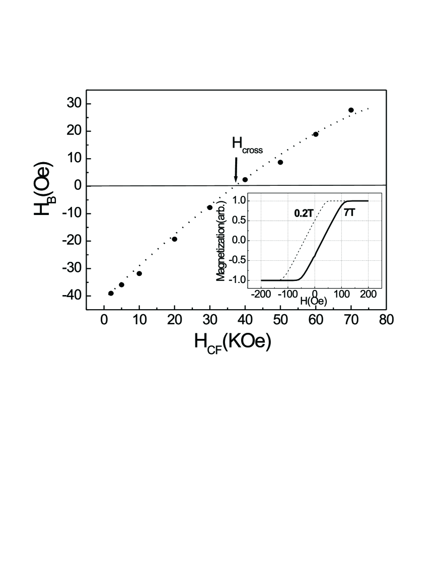
Fig.1 shows EB as a function of cooling field for a AFM/FM system with low TN such as or . In doing this we set the parameters in Hamiltonian as and per siteReview , Koon , Butler . As a natural output from the calculation, it is indeed observed in this figure that the exchange bias changes sign from negative to positive as the cooling field increases, and a crossover field is found at about . Dashed and solid lines in the inset show the negative and positive loops at 2KOe and respectively.
For systems with low TN, i.e., weak spin-spin interaction in AFM, the spin configuration of AFM at low cooling magnetic field is dominated by AFM type interface coupling of FM/AFM. In this case, the symmetry broken of compensated AFM layers appears. Some net ferromagnetic component along the axis is expected, which means that the broken symmetry of AFM in this case favors the negative exchange bias. However for higher cooling magnetic field , the cooling field becomes to dominate the broken symmetry so that a net ferromagnetic component along the positive direction is expected, i.e., the broken symmetry of AFM in this case favors the positive exchange bias.
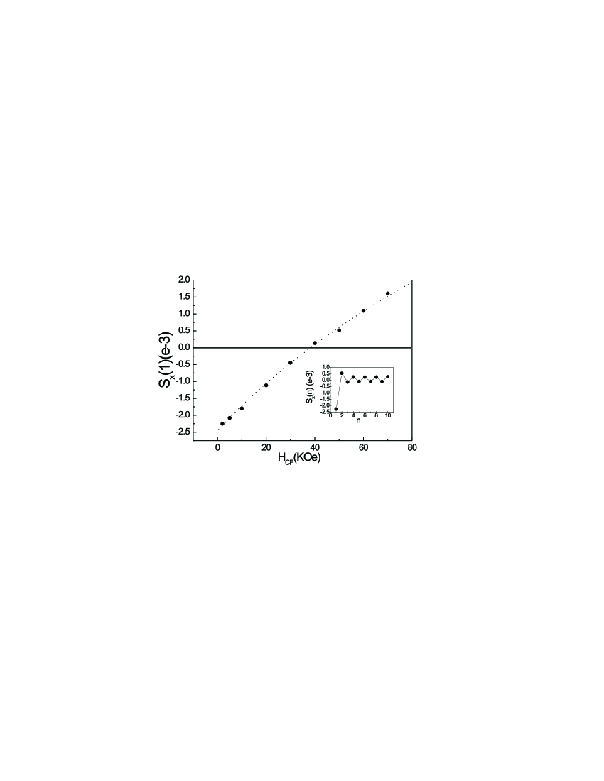
For a quantitative description of the FM components in AFM, We define the ferromagnetic component in the n-th AFM layer
| (5) |
where is the AFM spin at site of the n-th layer, is the number of lattices in the n-th AFM layer, while the first layer is defined as the interface layer of AFM. This quantity describes the degree of symmetry broken in each layer of AFM. It is found from our calculation that the ferromagnetic components are layer dependent. As expected, it will be larger when the layer is near the interface, and become smaller when the layer is far from the interface. In Fig.2 the ferromagnetic component of the interface AFM layer is shown as a function of , using the same parameters as obtaining Fig.1. Similar results as Fig.1 are found, that is negative at the beginning when the cooling field is small, then reaches to zero at a critical field and finally becomes positive as the field further increasing. Since the first AFM layer should be the most important one in the interface coupling, it is reasonable to see that the ferromagnetic component of the interface AFM layer should be responsible for the EB effect. The inset of Fig.2 gives the layer dependent ferromagnetic components when the cooling field is fixed at 2KOe. The oscillation is caused by the antiferromagnetic exchange interaction between the layers of AFM.
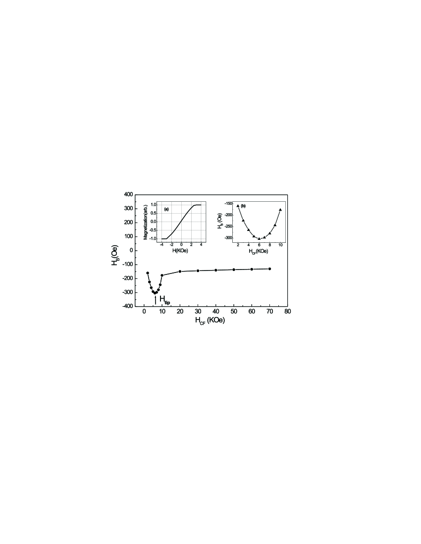
Fig.3 shows the same relationship but for a AFM/FM system with higher such as FeMn . The parameters used here are and per site Review . In this case, it is found that is always negative and changes a little when is ranged from 2T to 7T. This result also agrees qualitatively with experimentReview . Inset(a) of Fig.3 shows the magnetization loop at 3T cooling field. In fact that is large when the AFM layer of the system has high thus the interface coupling also becomes large , then the AFM type interface coupling controls the symmetry broken of AFM. In this case, if is reasonable high but not too high, is found to be always negative. This can explain that the positive EB was reported only in the FM/AFM thin films with low TNPositive , Postive2 - Coupling .
One distinguished feature of Fig.3 is that: a tip EB is found at cooling field indicated by arrow, and this tip also is clearly shown in Inset(b). As previous mention, the preceding discussions are subjected to both cooling field and applied magnetic field parallel with AFM easy axis. In fact, the orthogonal FM/AFM spin configuration similar to Koon’s conclusion can also be recovered with zero or smaller cooling field for stable spin configuration. With the increasing cooling field from zero to , the FM spins will gradually rotate direction from the perpendicular to parallel to the AFM easy axis during cooling process, and the interface coupling contribution to the negative bias will enlarge and nearly saturate at . On the other hand, with the increasing cooling field above , the cooling field contribution to the potentially positive bias will raise, in other words, contribution to the negative bias will lessen. Thus for cooling field parallel with AFM easy axis situation, there exists a tip EB associated with cooling field .
In summery, micromagnetic spin dynamics calculations are carried out to explain the mechanism of EB in the FM/compensated AFM system. Different from the previous micromagnetic calculations, we address the key role of cooling field. Some important experiment results, such as the cooling field dependent transition from negative to positive EB in the AFM/FM layers with low TN, can be reproduced. It is proposed that the symmetry broken of AFM plays a key role in explaining the exchange bias.
This work is supported by the National Natural Science Foundation of China and Shanghai Research Center of Applied Physics. One of the authors X.F. Jin would acknowledge the supports of the Cheung Kong Scholars Program, Hong Kong Qiushi Science Foundation, Y.D. Fok Education Foundation.
References
- (1) W.H. Meiklejohn, C.P. Bean, Phys. Rev. 102, 1413 (1956) ; 105, 904 (1957).
- (2) B.Dieny, V.S.Speriosu, S.S.P.Parkin, B.A.Gurney, D.R.Wilhoit, and D.Mauri, Phys. Rev. B43, 1297 (1991).
- (3) J.Nogués, Ivan K.Schuller, J.Magn. Magn. Mater. 92, 203 (1999) ( review Paper).
- (4) A.E. Berkowitz, K. Takano, J.Magn. Magn. Mater. 200, 552 (1999) ( review Paper).
- (5) J.Nogués, D.Lederman, T.J.Moran and Ivan K.Schuller, Phys. Rev. Lett. 76, 4624 (1996).
- (6) N.C.Koon, Phys. Rev. Lett. 78, 4865 (1997).
- (7) T.C. Schulthess and W.H.Butler, Phys. Rev. Lett. 81, 4516 (1998).
- (8) T.M.Hong, Phys. Rev. B58, 97(1998).
- (9) M. Kiwi, J. Mejia-Lopez, R. D. Portugal and R. Ramirez, Europhysics Letters 48, 573 (1999); M. Kiwi, J. Mejia-Lopez, R. D. Portugal, R. Ramirez, Solid State Commun.116, 315 (2000).
- (10) J. Nogués, T.J. Moran, D. Lederman, Ivan K. Schuller, and K.V. Rao, Phys. Rev. B59, 6984 (1998).
- (11) C. Leighton, J. Nogués, H. Suhl, and Ivan K. Schuller, Phys. Rev. B60, 12 837 (1999).
- (12) J.Nogués, C.Leighton, Ivan K.Schuller, Phys. Rev. B61, 1315 (2000).
- (13) F.Nolting, A.Scholl, J.Stöhr, et al, Nature. 405, 767 (2000).
- (14) V.I.Nikitenko, V.S.Gornakov, A.J.Shapiro, R.D.Shull, Kai Liu, S.M.Zhou and C.L.Chien, Phys. Rev. Lett. 84, 765 (2000).
- (15) M.R.Fitzsimmons, P.Yashar, C.Leighton, Ivan K.Schull, J.Nogués, C.F.Majkrzak and J.A.Dura, Phys. Rev. Lett. 84, 3986 (2000).