Continuous detection of an atom laser beam
Abstract
We have demonstrated a detection scheme for atom laser beams that allows for a continuous measurement of the atom density and readout of the data in real-time. The atoms in the atom laser beam are transferred locally from the lower to the upper hyperfine ground state of 87Rb by coherent coupling and are subsequently detected by an absorption measurement. The detection is non-destructive to the Bose-Einstein condensate in the magnetic trap and the atom laser beam remains unaffected outside the detection region.
pacs:
03.75.Fi, 32.80.-tThe possibility to extract coherent atomic beams from Bose-Einstein condensates [1] has stimulated enormous theoretical and experimental interest in this field. Very recently, the temporal coherence of atom laser beams was measured [2] and their transverse divergence investigated [3]. For studies of atom laser beams only absorption imaging has been employed so far. This technique is destructive since the atoms scatter near-resonant photons and it therefore allows only for single shot measurements. The technique of phase-contrast imaging [4], where the atoms scatter light far off resonance, is almost non-destructive and several repetitive measurements of a single Bose-Einstein condensate have been obtained. However, phase contrast imaging requires large atomic densities. It is therefore only suitable for imaging Bose-Einstein condensates in the magnetic trap but not for atom laser beams which usually have two to three orders of magnitude lower densities. Also, the repetition rate for phase contrast imaging is typically a few hundred Hz which limits the temporal resolution to values larger than a millisecond.
Besides being non-continuous there is another major drawback of the existing imaging techniques: the time delay between the actual measurement and the readout of the data. For slow-scan CCD cameras this is typically a few hundred milliseconds and hinders the realization of experiments where a measured quantity, e.g. the optical density at a certain position, is fed back onto the condensate.
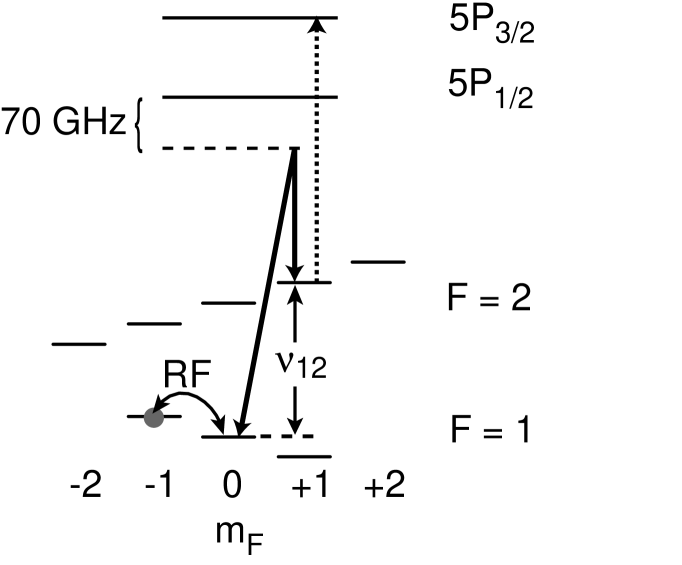
We have demonstrated a continuous detection of an atom laser beam with readout of the data in real-time. The detection scheme employs a position-dependent coherent coupling between the hyperfine ground states and of 87Rb. Atoms in the atom laser beam are transferred locally from the into the hyperfine ground state, in which they are detected by an absorption measurement (see Fig. 1).
The experimental procedure for the production of continuous atom laser beams has been described previously [5]. Briefly, we load about atoms in the hyperfine ground state into a magnetic Quadrupole-Ioffe configuration trap (QUIC-trap) [6]. The trapping frequencies are Hz in the radial and Hz in the axial direction. In the magnetic trap we perform forced evaporative cooling for about 30 s after which Bose-Einstein condensates of atoms are obtained. Continuous atom laser beams are extracted from the condensate by employing a weak, monochromatic radio frequency field that induces locally spinflip transitions of condensed atoms into the magnetically untrapped state . Atoms in this state are accelerated by gravity, propagate downward and form a collimated beam.
After a dropping distance of about 500 m the atoms enter a region of focused, co-propagating laser beams which have a cylindrical waist with 1/e2-radii of 26 m and 500 m in the vertical and horizontal direction, respectively. Two of these laser light fields couple the state and the state by a two photon hyperfine Raman transition (see Fig. 1) [7]. The resonance condition for this transition is given by the frequency difference between the Raman laser light fields and the local magnetic field, which induces a spatially dependent Zeeman shift for the state. The Raman lasers are detuned by 70 GHz to the red of the 5S1/2 5P1/2 transition (D1-line, 795 nm) and the power needed to achieve 100% transfer between the different hyperfine levels is for our geometry 1 mW. Additionally, laser light resonant with the transition of the D2-line (5S1/2 5P3/2, 780 nm) is superimposed to the pair of Raman laser beams. As soon as the atoms are transferred into the state they absorb light out of this beam and its extinction is a measure of the density of the atom laser beam.
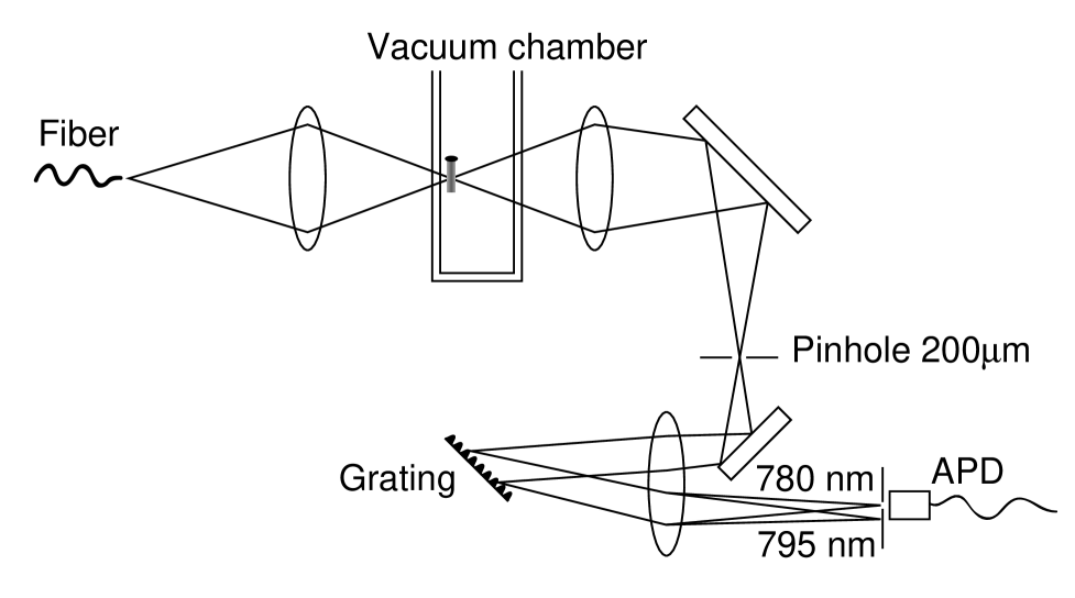
The laser light for the Raman transition and for the absorption detection is generated by grating stabilized diode lasers and is guided by a single mode optical fiber to the vacuum chamber (see Fig. 2). The interaction region between the atoms and the laser beams is imaged by a lens onto a pinhole of 200 m diameter. The magnification of the imaging system is 4 so that the transverse size of the atom laser beam matches that of the pinhole and laser light which has not illuminated the atom laser beam is blocked. After the pinhole the laser beams are collimated and the different wavelengths are separated by a grating spectrometer in Littrow configuration. The difference in wavelength between the Raman laser light on one side and the absorption laser light on the other side is 15 nm which can easily be resolved using a grating with 1800 lines/mm. The diffraction efficiency into the 1st order is better than 80%. The absorption laser light (780 nm) is detected by an avalanche photo diode (APD), which is cooled to C and the signal is recorded by a digitizing oscilloscope.
The intensity of the absorption light is chosen to be 1/5 of the saturation intensity of 1.6 mW/cm2 to prevent saturation of the optical transition. The laser power incident onto the atom laser beam is about 5 nW. This low light level requires very high gain in the detection electronics. The avalanche photo diode has an internal gain of more than 100 A/W and the photo current is subsequently amplified by low-noise amplifiers. The measured RMS noise corresponds to 5 nA photo current, which is a factor five larger than the specified dark current of the avalanche photo diode. With a reduction of the bandwidth of the electronics (currently about 10 kHz) one might approach the dark current noise limit. The signal-to-noise ratio may also be improved by intensity stabilizing the absorption laser or by making a differential measurement by comparing the absorption signal with the time dependent intensity of the absorption laser beam using two identical photo diodes.
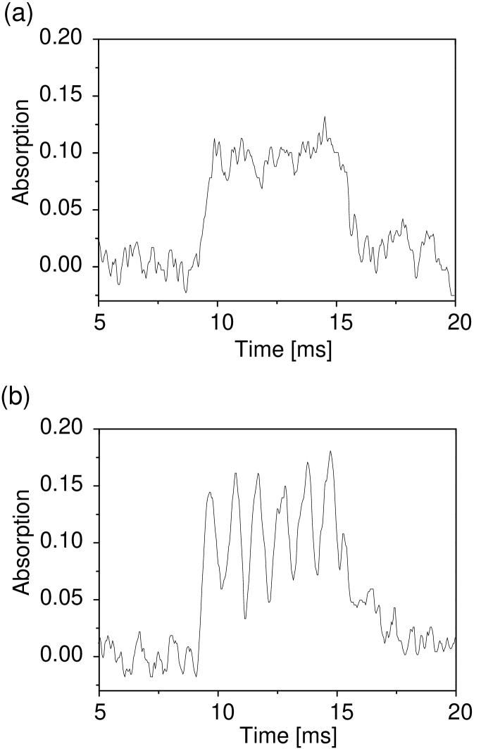
Fig. 3 shows the data of absorption traces of the atom laser beam. The signal of an atom laser beam which is extracted for a duration 6 ms from a Bose-Einstein condensate is shown in Fig. 3a. The time axis is counted from the beginning of the output coupling.
A modulated density of the atom laser beam is obtained, when the output coupling is performed with two different radio frequencies. The two extracted atom laser beams interfere and the fringe pattern depends on the difference between the radio frequencies. Such interference pattern have been observed in the spatial domain [8] where the the fringe spacing is position dependent due to the acceleration of the atoms in the gravitational field. However, in the time domain the fringe spacing is given by the frequency difference of the RF fields. Figure 3b shows the absorption signal of two interfering atom laser beams with an energy difference of 1 kHz. This results in the temporal modulation of the absorption signal with 1 ms periodicity.
The presented technique is non-destructive for the Bose-Einstein condensate and those parts of the atom laser beam that have not yet reached the detection region. Both, the condensate and the atom laser beam are formed in the hyperfine ground state. With respect to this state the Raman lasers are detuned 70 GHz from the 5S1/2 5P1/2 single photon resonance and the very weak absorption light is detuned 6.8 GHz from the 5S1/2 5P3/2 single photon resonance, i.e. all light fields are far detuned and spontaneous scattering is suppressed. In contrast, optical pumping always requires scattering of resonant photons which imposes a great risk of an unwanted heating the sample by stray light.
The temporal resolution of the detection scheme is determined by the transit time of the atoms through the interaction region. For a dropping distance of 500 m and a waist of the absorption laser beam of 26 m in the vertical direction, the resolution is about 260 s. The temporal resolution may be increased by either employing faster atoms (e.g. after a larger dropping distance or after acceleration by magnetic forces) or by focusing the absorption laser to a smaller waist. Obtaining a temporal resolution of a few ten microseconds appears feasible with this scheme.
The continuous detection allows for the investigation of processes with long time constants. For example, we could for the first time monitor atom laser output coupling for up to 300 ms. Since the energy width of an atom laser is dependent on the output coupling duration [2], with long extraction times one might approach energy widths of a few Hz, where phase diffusion processes in the condensate become observable [9]. Another application could be the online monitoring of the growth of a Bose-Einstein condensate. The formation takes place on the time scale of a few hundred milliseconds [10, 11, 12] and the increase of atomic density will clearly show up in the atom laser signal. The presented method may also prove to be a crucial tool for investigations of continuous atom laser schemes.
In conclusion, we have presented a scheme to detect atom laser beams continuously. The scheme is non-destructive to the Bose-Einstein condensate in the trap and to those parts of the atom laser beam, which have not yet entered the detection region. Continuous atom laser operation for 300 ms has been observed and the data are obtained in real-time, which might enable experiments with feedback.
We would like to thank A. Scheich for assistance with the photo diode, and DFG for financial support.
REFERENCES
- [1] M. -O. Mewes et al., Phys. Rev. Lett. 78, 582 (1997); B. P. Anderson and M. A. Kasevich, Science 282, 1686 (1998); E. W. Hagley et. al., Science 283, 1706 (1999); I. Bloch, T. W. Hänsch, and T. Esslinger, Phys. Rev. Lett. 82, 3008 (1999).
- [2] M. Köhl, T. W. Hänsch, and T. Esslinger, Phys. Rev. Lett., in press (2001).
- [3] Y. Le Coq et al., cond-mat/0107032.
- [4] M. R. Andrews et al., Science 273, 84 (1996).
- [5] I. Bloch, T. W. Hänsch, and T. Esslinger, Phys. Rev. Lett. 82, 3008 (1999); T. Esslinger, I. Bloch, and T. W. Hänsch, Laser Spectroscopy XIV, ed. R. Blatt, J. Eschner, D. Leibfried, F. Schmidt-Kaler, Singapore (1999).
- [6] T. Esslinger, I. Bloch, and T. W. Hänsch, Phys. Rev. A 58, R2664 (1998).
- [7] I. Bloch, M. Köhl, M. Greiner, T. W. Hänsch, and T. Esslinger, Phys. Rev. Lett. 87, 030401 (2001).
- [8] I. Bloch, T. W. Hänsch, and T. Esslinger, Nature 403, 166 (2000).
- [9] R. Graham, Phys. Rev. Lett. 81, 5262 (1998), and references therein.
- [10] H. J. Miesner et al., Science 279, 1005 (1998).
- [11] A. Robert et al., Science 292, 461 (2001).
- [12] M. Köhl, T. W. Hänsch, and T. Esslinger, cond-mat/0106642.