Colloidal dipolar interactions in 2D smectic C films
Abstract
We use a two-dimensional (2D) elastic free energy to calculate the effective interaction between two circular disks immersed in smectic- films. For strong homeotropic anchoring, the distortion of the director field caused by the disks generates additional topological defects that induce an effective interaction between the disks. We use finite elements, with adaptive meshing, to minimize the 2D elastic free energy. The method is shown to be accurate and efficient for inhomogeneities on the length scales set by the disks and the defects, that differ by up to 3 orders of magnitude. We compute the effective interaction between two disk-defect pairs in a simple (linear) configuration. For large disk separations, , the elastic free energy scales as , confirming the dipolar character of the long-range effective interaction. For small the energy exhibits a pronounced minimum. The lowest energy corresponds to a symmetrical configuration of the disk-deffect pairs, with the inner defect at the mid-point between the disks. The disks are separated by a distance that is twice the distance of the outer defect from the nearest disk. The latter is identical to the equilibrium distance of a defect nucleated by an isolated disk.
I Introduction
Colloidal systems consist of a dispersive medium or solvent and a dispersed phase. The size of the dispersed domains or colloids is large compared to atoms but small compared to macroscopic lengths. Thus these systems exhibit new phenomena that are challenging theoretically while they are of practical importance in a variety of applications, from paints and coatings to food and drugs [1].
The colloidal state is metastable and its life-time is determined (largely) by the effective interactions between colloids. In many systems these interactions are tunable through the control of one or more external parameters. To prevent phase separation due to van der Waals or other attractive interactions, the colloids are coated or charged to induce steric or electrostatic repulsions [1]. Recently, a novel mechanism of colloidal interactions was reported: the elastic distortion of a liquid crystal host in a reverse nematic emulsion [2], i.e., an emulsion of water droplets in a nematic liquid. This interaction arises from a competition between the aligning properties of the spherical droplet surfaces that favour e.g., a radial (homeotropic) nematic orientation and the bulk elasticity and boundary conditions that favour a uniform nematic. This effect is generic and it arises in a variety of anisotropic liquids for different isotropic inclusions. In addition, elastic mediated interactions were shown to be effective above the bulk nematic-isotropic temperature, for colloids wet by the nematic phase [3]. Finally, under appropriate conditions, inverted nematic emulsions exhibit colloidal self-organization, i.e., new phases where the colloids are ordered over macroscopic distances [4, 5].
Understanding the phase behaviour of these complex systems begins by identifying the mechanisms and calculating the effective interactions between colloids. This is far from a simple task owing to the non-linear nature of the nematic elasticity and the existence of widely different length scales: the bulk correlation length that sets the scale for variations of the microscopic degrees of freedom, such as nematic order, biaxility etc., and the size of the colloids that sets the scale for variations of the elastic degrees of freedom, i.e., the nematic director field, [6]. Both microscopic (molecular dynamics simulations [7], tensor order-parameter free energy [8]) and macroscopic (elastic free energy minimization using: trial functions [2, 9], simulated anealing [10], finite elements [11] and electrostatic analogies [12]) approaches have been used to calculate the orientational order of a nematic in the presence of a single colloid, in 2 and 3 dimensions.
Theoretical [9, 10, 11] and experimental [2, 13, 14] work on inverted nematic emulsions in 3D, reveals that for sufficiently strong homeotropic anchoring, spherical droplets induce topological defects, i.e., singularities in the nematic director field. There are several of these defects and their stability depends on parameters such as the size of the droplet, the anchoring strength and the boundary conditions. When the size of the droplet is large, a hyperbolic point defect appears at a certain distance from the droplet, and this structure is known as the satellite configuration [9, 10, 11]. For smaller droplets and/or weaker anchoring strengths, the minimum elastic free energy corresponds to a ring disclination that surrounds the droplet on the equatorial plane, and this structure is known as the saturn-ring configuration [9, 10, 11]. The distortion of the director field due to the presence of more than one of these colloids induces multipolar long-range interactions between the colloids [2, 15, 16]. Depending on the symmetry of the distortion, the dominant long-range interactions are dipolar [15] or quadrupolar [17, 14]. At short range, however, the colloids repel each other [16] and this prevents their colapse.
A 2D system was also investigated by Pettey et al. [12] who obtained analytic solutions for the smectic- director around circular disks. For a disk at the center of a smectic- layer, the solution that minimizes the elastic free energy exhibits a hyperbolic point defect, at a distance from the center. The free energy of a system of multiple disk-defect pairs was also obtained, for pairs that are far apart. For defects aligned with the far field director, a dipole-dipole interaction results between the colloids [12]. These predictions were tested in a recent experiment by Cluzeau et al. [18]. Thin films of smectic- were heated and the temperature was stabilized when cholesteric () droplets started to nucleate. Cluzeau and collaborators observed that a hyperbolic point defect is nucleated with each cholesteric droplet, at the distance predicted by theory. In addition, they observed that the droplets interact through a long-range attraction and assemble into chains, confirming the dipolar nature of the interaction. Finally, they measured a mean separation between nearest-neighbor droplets in chains, where is the droplet average diameter.
Even in 2D exact solutions are not readily obtained. The analytic solutions of [12] are restricted to one inclusion or to multiple inclusions that are sufficiently far apart. Recently, Fukuda and Yokoyama solved the 2D problem using the tensor order parameter formalism and an efficient adaptive grid method to integrate numerically the dynamic equation [8]. One of the advantages of this method is that no special treatment of topological defects is required, by contrast with the director description, where defects appear as singularities of the director field [6]. For all the parameters used in [8], the authors found that the equilibrium director configuration around a circular disk, exhibits quadrupolar symmetry and corresponds to two defects with topological charge -1/2. This contrasts with the 3D result, where the quadrupolar defect was found to be stable over a limited range of parameters. It is also in apparent contradiction with the experiment on 2D smectic- films [18]. The latter, however, do not exhibit mirror symmetry about reflection of the 2D director, excluding a distortion with quadrupolar symmetry [21, 6].
In this paper we use finite elements and adaptive meshes to minimize the 2D elastic free energy functional. We focus on dipolar distortion fields as observed in the experiments [18]. In particular, we study the interaction between two disks of equal radii, , in a large smectic- layer. The minimal free energy occurs when the two dipoles are aligned head to tail, in a direction parallel to the far field director. In this geometry we investigated a wide range of disk separations. We verified the validity of the electrostatic analogy at large distances and calculated the short-range repulsive interaction between two disks.
II Model and numerical method
The free energy of a nematic is invariant under uniform rotations of the whole sample and under the symmetry operations and . In addition, is a unit vector so that is zero. These considerations imply that the stiffness tensor has 2 independent bulk components in 2D. The distortions whose energy is measured by these constants are (1) splay, with non-zero , and (2) bend, with non-zero . The elastic free energy for the bulk nematic phase, is the sum of these terms [22, 6]:
| (1) |
where and are the elastic constants associated with splay and bend distortions, and is the 2D nematic director. The integral is over the region occupied by the 2D nematic film.
Note that if , the elastic free energy is proportional to (plus boundary terms) which is the form produced by simple models of the nematic state, such as those with pairwise intermolecular interactions depending only on the angle between the long molecular axes or the 2D XY-model [12].
| (2) | |||||
| (3) |
Line and boundary terms have been ignored in (3) which is justified in the strong anchoring regime (fixed orientation at the boundaries) for systems with large line tensions (inclusions with fixed shape) since their contribution to the free energy is constant. The one elastic constant approximation (3) is not strictly necessary, since the numerical method to be described below can be applied to the Frank free energy (1); the choice of (3) however, allows a direct comparison with the analytical results of [12] and provides a stringent test of our numerics.
The geometry used in the numerical calculations is shown schematically in figure 1a. We consider two circular disks of radius separated by a distance . Close to each disk we pin a defect at distances and measured from the center of each disk, respectively. The system has mirror symmetry with respect to -axis. Thus, the center of the disks and the accompanying defects are located on the -axis. The smaller circles around the defects are the defect cores (regions where the nematic order is destroyed [6]). They are used as cut-offs for the integral of the elastic free energy density (3). Lengths are measured in units of and energy is measured in units of .
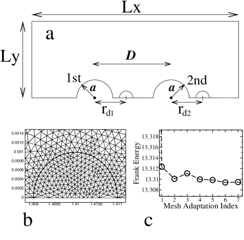
We fixed the nematic orientation, , at the physical boundaries. The far field director was taken parallel to the axis () and homeotropic boundary conditions were imposed at the disk perimeters. The solution for the director field is found by minimizing the total free energy of the system, using standard numerical procedures [19]. The major difficulty in the numerical problem stems from the large difference in the length scales set by the disk and the defect. It was overcome by using adaptive meshing techniques. With the help of a 2D mesh generator [20] (BL2D package), a first triangulation respecting the predefined physical boundaries, as well as the defect cores, is constructed. A final grid for the region close to a defect is shown in figure 1b and was obtained after several adaptation loops. Note that in addition to the outer boundaries (figure 1a), the triangulation follows the perimeter of the defect core. Using standard numerical procedures the elastic free energy is minimized in a region that includes the defect core. The elastic free energy of the core region is subtracted at the end of the calculation. The core energy was set to zero [6].
Adapted meshes may be generated if the Hessian of the solution, , is known. Far from the disks, varies slowly and the triangles can be large. By contrast, close to the defects, the Hessian is large (it diverges at ) and the triangles have to be made several orders of magnitude smaller. The Hessian, , at vertex is estimated [23] by using the following ’weak’ definition ([20], p. 349)
| (4) |
where the integral is over the region occupied by the smectic layer. is the piecewise linear hat function associated with vertex ( at vertex and elsewhere), and . To construct an anisotropic non-uniform mesh, we require a metric map that distributes the interpolation error, i.e., the difference between the interpolated function and the exact solution, in a uniform fashion [20]. The required map, , at vertex is a two dimensional positive definite matrix given by
| (5) |
where is the orthogonal matrix that diagonalizes the Hessian , and and the corresponding eigenvalues. The constant controls the number of mesh triangles. To avoid problems caused by the divergence of the Hessian, the eigenvalues are bounded by
| (6) |
where and are the minimal and maximal mesh edge lengths.
As a test of the numerics, we considered one single disk in a smectic- film. We calculated the free energy as a function of the defect distance , for a dipole parallel to the far field director. The equilibrium free energy was found for a defect at , in good agreement with the analytical result for small defects () [12] and in line with the experimental result for inclusions of cholesteric droplets in smectic- films () [18].
III Results
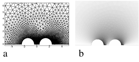
In the calculations, we used a rectangular integration region of size (see figure 1a). With the adaptive mesh technique we have studied defects with cores as small as , with a minimal mesh edge length of . During the adaptation loops this limit was reached close to and inside the cores, providing a good discretization of the core region (see figure 1b). The final mesh configuration contained up to vertices. After 4 or 5 iterations of the adaptive mesh procedure, the relative error of the free energy is of the order of (see figure 1c). For a particular geometry, the central part of the final mesh is shown in figure 2a. In figure 2b, a gray scale was used to plot the corresponding equilibrium tilt angle, . White is and black .
Near the core (in a small region of size ) the elastic distortion field is determined by the defect alone. We have checked numerically that a change in the core size from to leads to a free energy difference of [12], independent of the position of the disks.
For these systems (small defect cores) we found that the separation of the disks had no influence on the position of the outer defect, : the minimum free energy was obtained for an outer defect at , the position of the defect for an isolated disk, i.e., independent of the presence of the first disk. In what follows we set .
The elastic free energy as a function of the position of the inner defect, , is shown in figure 3a, for several disk separations. The lowest free energy was found for a disk separation , with an inner defect at .
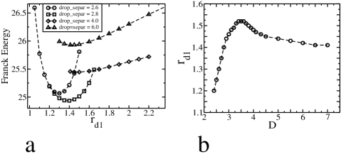
In figure 3b we plot the position of the inner defect, , that minimizes the elastic free energy, as a function of the disk separation, . We identify three regimes. For small disk separations () the position of the inner defect, , is symmetrical with respect to the disks and scales linearly with , namely , i.e., the defect is at the mid-point between the disks. In the intermediate regime () the defect position varies non-monotonically with D, reaching a maximum, , at . Finally, for large disk separations () the position of the inner defect is independent of D and is given by that of an isolated disk, , i.e., it is independent of the presence of the second disk.
Note that the minimal free energy corresponds to a symmetrical configuration: the inner defect is at a distance from the first disk identical to the distance of the outer defect from the second disk.
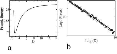
Finally, we plot the elastic free energy as a function of the disk separation, , in figure 4a. The free energy exhibits a pronounced minimum at , close to the value observed experimentally by Cluzeau et al. [18], for chains of (polydispersed) circular droplets. Note that the experimental estimate of D, if taken without error bars, suggests that the inner defect is nucleated at a distance smaller than the distance corresponding to isolated droplet-defect pairs. This configuration, however, is ruled out by our model (see figure 3a, open circles and squares). Within the (large) error bars we conclude that the experimental result is in line with the theoretical prediction: the lowest free energy corresponds to a symmetrical configuration, with the inner defect at a distance from the disks that is identical to the distance of deffects in isolated disk-defect pairs.
Admitedly, some effects were left out from our calculation, the most important of which is arguably that of fluctuations. In fact, fluctuations were predicted to be important in 2D [12] but were reported to be negligible in the rather thick films studied by Cluzeau et al. [18]. It is possible that many-body interactions may account for a reduction in disk separation for disks in chains, when compared to the equilibrium separation of a pair of disks. This could be checked within our model by calculating the free energy of three interacting disks. The experimental results, however, suggest that this effect, if present, is of the order of the experimental error. A smaller disk separation, than that predicted by our model, may also result from surface contributions that were oversimplified in (3). In fact, deviations from strong homeotropic anchoring at the disks reduce the effective size of the inclusions, leading to a smaller equilibrium distance between disks [24].
The signature of the dipolar interaction for large disk separations may be seen in figure 4b. Here, the circles are the (calculated) force between disks, as a function of their separation. The force is clearly a power law that decays as . Note that the numerical results for the force are less accurate than those of the free energy, since they were obtained by numerical differentiation of the latter, figure 4a.
IV Summary and Conclusion
We studied the interaction of two circular disks immersed in smectic- films. For strong homeotropic anchoring the circular disks nucleate topological defects of the 2D director field. We implemented a finite elements, with adaptive meshing, numerical method capable of dealing with the variation of the director field over the widely different length scales set by the disks and the defects. The method allows the construction of well defined core regions around the defects and leads to very accurate results for the elastic free energy.
We have verified the long-range dipolar character of the interaction between disk-defect pairs, predicted by Pettey et al. [12]. In addition, we have calculated the interaction at small disk separations, and found that at static equilibrium, the distance between the centers of the disks is equal to .
Finally, we have determined the position of the inner defect, as a function of the separation between disks. For small disk separations the defect is located symmetrically at the mid-point between the disks. At intermediate separations, this symmetry is broken and the position of the defect reaches a maximum for a disk separation, . Finally, at large disk separations the defect relaxes slowly to the equilibrium position, , of an isolated disk.
We intend to use the numerical method described in this paper to study the properties of other reverse nematic emulsions in 2 and 3D. In particular, we will consider the quadrupolar defects, recently studied by Fukuda and Yokoyama [8] using a tensor order parameter formalism. Although these authors concluded that the dipolar configuration is dynamically unstable, and the quadrupolar configuration is the only one allowed in 2D nematics, the energetics of these two types of pinned defects has not been compared.
Acknowledgments
PP thanks J. M. Tavares for get him interested in this problem and for helpful discussions. We also thank Francisco de los Santos for useful comments.
We acknowledge the support of the Fundação para a Ciência e a Tecnologia (FCT) through a running grant (Programa Plurianual) and grants No. PRAXIS XXI/BPD/16309/98 (PP) and No. SFRH/BPD/1599/2000 (M.T.).
REFERENCES
- [1] W. B. Russel, D. A. Saville, W. R. Schowalter, “Colloidal Dispersions” (Cambridge Univ. Press, Cambridge, 1989)
- [2] P. Poulin, H. Stark, T. C. Lubensky and D. A. Weitz, “Novel colloidal interactions in anisotropic fluids”, Science 275, 1770 (1997)
- [3] P. Galatola and J. B. Fournier, “Nematic-wetted colloids in the isotropic phase: pairwise interaction, biaxiality and defects”, Phys. Rev. Lett. 86, 3915 (2001)
- [4] J.-C. Loudet, P. Barois and P. Poulin, “Colloidal ordering from phase separation in a liquid-crystalline continuous phase”, Nature 407, 611 (2000)
- [5] J.-C. Loudet, P. Poulin and P. Barois, “Edge dislocations of colloidal chains suspended in a nematic liquid crystal”, Europhys. Lett., 54, 175 (2001)
- [6] P. M. Chaikin and T. C. Lubensky, “Principles of condensed matter physics” (Cambridge Univ. Press, Cambridge, 1995)
- [7] D. Andrienko, G. Germano and M. P. Allen “Computer simulation of topological defects around a colloidal particle dispersed in a nematic host”, Phys. Rev. E, 63 041701
- [8] J. Fukuda and H. Yokoyama, “Director configuration and dynamics of a nematic liquid crystal around a two-dimensional spherical particle : Numerical analysis using adaptive grids”, Eur. Phys. J. E 4, 389 (2001)
- [9] T. C. Lubensky, D. Pettey, N. Currier and H. Stark, “Topological defects and interactions in nematic emulsions”, Phys. Rev. E 57, 610 (1998)
- [10] R. W. Ruhwandl and E. M. Terentjev, “Monte Carlo simulation of topological defects in the nematic liquid crystal matrix around a spherical colloid particle”, Phys. Rev. E 56, 5561 (1997)
- [11] H. Stark, “Director field configurations around a spherical particle in a nematic liquid crystal”, Eur. Phys. J. B 10, 311 (1999)
- [12] D. Pettey, T. C. Lubensky and D. R. Link, “Topological inclusions in 2D smectic C films”, Liq. Cryst. 25, 5 (1998)
- [13] Y. Gu and N. L. Abbott, “Observation of saturn-ring defects around solid microspheres in nematic liquid crystals”, Phys. Rev. Lett. 85, 4719 (2000)
- [14] O. Mondain-Monval, J. C. Dedieu, T. Gulik-Krzywicki and P. Poulin, “Weak surface energy in nematic dispersions: saturn rings defects and quadrupolar interactions”, Eur. Phys. J. B 12, 167 (1999)
- [15] P. Poulin, V. Cabul and D. A. Weitz, “Direct measurement of colloidal forces in an anisotropic solvent”, Phys. Rev. Lett. 79, 4862 (1997)
- [16] H. Stark, J. Stelzer and R. Bernhard, “Water droplets in a spherically confined nematic solvent: a numerical investigation”, Eur. Phys. J. B 10, 515 (1999)
- [17] O. V. Kuksenok, R. W. Ruhwandl, S. V. Shiyanovskii and E. M. Terentjev, “Director structure around a colloid particle suspended in a nematic liquid crystal”, Phys. Rev. E 54, 5198 (1996)
- [18] P. Cluzeau, P. Poulin, G. Joly and H. T. Nguyen, “Interacions between colloidal inclusions in two-dimensional smectic- films”, Phys. Rev. E 63, 031702 (2001)
- [19] W. H. Press, S. A. Teukolsky, W. T. Vetterling and B. P. Flannery, “Numerical Recipes”, Cambridge University Press, 2nd ed. (1992)
- [20] P.-L. George and H. Borouchaki, “ Delaunay triangulation and meshing : Application to finite elements”, Paris : Hermes (1998)
- [21] P. G. de Gennes and J. Prost, “The Physics of Liquid Crystals”, 2nd ed., Clarendon Press, Oxford (1993).
- [22] F. C. Frank, “On the theory of liquid crystals”, Discuss. Faraday Soc, 25, 19 (1958).
- [23] Since we use linear finite elements interpolation – is given at the vertices of a triangle and linearly interpolated inside – the lowest order discrete Hessian is zero.
- [24] Y. Galerne, private communication.