Effect of quantum entanglement on Aharonov-Bohm oscillations, spin-polarized transport and current magnification effect
Abstract
We present a simple model of transmission across a metallic mesoscopic ring. In one of its arm an electron interacts with a single magnetic impurity via an exchange coupling. We show that entanglement between electron and spin impurity states leads to reduction of Aharonov-Bohm oscillations in the transmission coefficient. The spin-conductance is asymmetric in the flux reversal as opposed to the two probe electrical conductance which is symmetric. In the same model in contradiction to the naive expectation of a current magnification effect, we observe enhancement as well as the suppression of this effect depending on the system parameters. The limitations of this model to the general notion of dephasing or decoherence in quantum systems are pointed out.
keywords Entanglement, Aharonov-Bohm effect, spin-conductance,
dephasing, decoherence, current magnification.
PACS Nos 73.23.-b, 05.60.Gg, 72.10.-d, 03.65.Bz
I Introduction
In recent times there is a great deal of interest in mesoscopic systems, sparked by the advancement of technology. Experimental investigations on these systems have provided several surprising quantum behavior in total contrast to that anticipated from the classical theory of metals. One of the prominent mesoscopic effects is that of Aharonov-Bohm(AB) oscillations in the transport property of normal metal rings enclosing magnetic flux[2, 3, 4, 5, 6, 7]. Here AB oscillations are revealed [5] in the resistance of a small metal ring as a function of the magnetic field with a period equal to , the fundamental flux quanta. The oscillations in the resistance arise from the interference of electronic waves traversing the two alternative arms of the ring. The changing magnetic flux alters the relative phase difference between the probability amplitudes associated with different paths(upper and lower arms of the loop). The amount of flux is required to enforce a relative phase shift between two alternative paths, This leads to the constructive and destructive interference in the transmission of an electron across the conductor as one tunes the magnetic flux. At high temperatures the inelastic scattering length is much larger than the sample dimensions and as a result the transport is completely phase coherent, i.e., it is dominated by quantum interference effects. At very low temperatures the inelastic scattering length is much smaller than the sample dimensions which leads to classical behavior(loss of interference). This process is referred to as dephasing or decoherence as a result of the randomizing of the interfering particle’s phase. The decoherence mechanism signals the limits beyond which the system dynamics approaches the classical behavior and arises due to the coupling of a particle to its environment. This subject of intrinsic decoherence and dephasing is being pursued actively in the area of mesoscopic physics
In a double slit setup, interference results from the lack of knowledge of (or indistinguishability of) the electron path. Thus a measurement of which path the electron has taken, wipes out the interference pattern. It is known that in a ring interferometer the electron affects the environment and changes its state differently in the two arms of the ring thereby affecting the interference. This amounts to a measurement of the path of the interfering particle by the environment resulting in loss of interference. Such interferometers are thus also termed as “which-path” detectors. In an alternate picture, the environment affects the electron phase differently in the two arms, thus randomizing their relative phase difference leading to dephasing. The two views were shown to be equivalent[8]. It is well known that the electron-environment entanglement can also lead to decoherence[9]. However, unlike other approaches, entanglement leads to decoherence even in absence of any energy transfer [8]. Experiments have been carried out which are aimed at measuring these coherence properties and it has been observed for instance, by placing a micro-detector near one arm of the AB interferometer causes decoherence[10]. Thus motivated, we consider a simple model of dephasing in an Aharonov-Bohm ring with a spin-half impurity (spin-flipper) in one arm. This example also serves to illustrate the effect of multiple reflections on ”which-path” detection.
By introducing a magnetic impurity atom (to be referred to as the spin-flipper, or the flipper, for short) in one arm of the ring, one can couple the spin of the electron () to the spin of the flipper () via the exchange interaction [8, 2]. This leads to scattering of the electron in which the spin state of the electron and the impurity is changed without any exchange of energy. Additionally, this scattering leads to the entanglement-induced reduction of interference pattern [9]. Let the electron be incident from the left reservoir with its spin pointing “up” (see Fig. 1). The spin of the electron passing through the upper arm may or may not be flipped by the flipper. In the case that the spin is unflipped, one would expect the usual AB-oscillations of the transmission due to interference of the partial waves passing through the upper and the lower branches of the ring. However, in the case that the spin is flipped, one would think, guided by naive intuition, that a path detection has taken place and hence one would be led to conclude that the interference pattern for the spin-down component would be wiped out. This is true provided we consider only two forward propagating partial waves. However, there are infinitely many partial waves in this geometry which are to be superposed to get the total transmission. These arise due to the multiple reflections from the junctions and the impurity site. Consider, for example, an incident spin-up particle moving in the upper arm which is flipped at the impurity site and gets reflected to finally traverse the lower arm before being transmitted. Naturally, this partial wave will interfere with the spin-flipped component transmitted along the upper arm. This results in non-zero transmission for the spin-flipped electron. Thus on taking into account the multiple reflections (more than just two partial waves) the presence of magnetic impurity does not lead to ”which-path” information. However, we show that the presence of magnetic impurity does lead to the reduction of AB-oscillations.
Within the same model we also study spin-polarized transport[11]. We have discussed the symmetry properties of reflection and transmission coefficients of different spin channels in the presence of magnetic flux. In particular the spin-conductance which is related to the spin polarised transmission coefficient is shown to be asymmetric in flux reversal. We also study the current magnification effect[12, 13, 14]. In the case of a mesoscopic loop with unequal arms connected to two electron reservoirs at chemical potentials and via ideal leads, currents and flow in the lower and upper arm respectively of the loop such that total current is conserved in accordance with Kirchoff’s law. In general these two currents differ in magnitude and are individually smaller than the total current . However, in certain range of Fermi energies the current or may become larger than the total current . The property that current in one of the arms is larger than the transport current is referred to as current magnification effect. To conserve the total current at the junctions, the current in the other arm becomes negative, i.e., flows against the applied external field. In such a situation one can interpret that the negative current flowing in one arm continues to flow as a circulating current in the loop. The magnitude of the negative current in one of the arms flowing against the direction of the applied current is taken to be that of the circulating current. When the negative current flows in the upper arm the circulating current direction is taken to be anticlockwise (or negative) and when it flows in the lower arm the circulating current direction is taken to be clockwise (or positive). The circulating current here arises in the absence of magnetic field. Like AB effect, this effect too is purely quantum mechanical in origin. Even though quantum entanglement dephases AB oscillations, we find however, that in contradiction to the naive expectation of a reduction of current magnification, it leads to enhancement as well as suppression of the effect. This fact points out the limitations of a model based on the interaction induced entanglement of quantum states to the general understanding of dephasing in quantum systems.
II Theoretical Treatment
We study the problem using the quantum waveguide theory approach [7, 12, 13, 15] and the spin degree of freedom of the electron is dealt with in line with Ref. [16]. We consider an impurity consisting of a flipper capable of existing in M different discrete internal spin states and located at a particular position on the upper arm of the ring (see Fig. 1). The spin of the electron couples to the flipper spin via an exchange interaction . The magnetic flux threading the ring is denoted by and is related to the vector potential , being the ring circumference [15]. During passage of the electron through the ring, the total spin angular momentum and its -component remain conserved. We consider the incident electron to be spin-polarized in the up-direction.
Let be the length of the lower arm of the ring and the impurity atom be placed at a distance from the junction J1, being the remaining segment length of the upper arm. The various segments of the ring and its leads are labeled as shown in Fig. 1 and the wave functions in these segments carry the corresponding subscripts. The wave functions in the five segments for a left-incident spin-up electron can be written as follows[7, 15, 16]:
| (1) | |||||
| (2) | |||||
| (3) | |||||
| (4) | |||||
| (5) |
where , , is the wave-vector of incident electron. The wavefunction in Eqn.(1) is a correlated function (entangled state) of the electron and the impurity spin which takes into account that the exchange interaction conserves the -component of the total spin[16]. The subscripts and represent “up” and “down” spin states of the electron with the corresponding spinors and respectively (i.e., , ) and denotes the wave function of the impurity [16] with (i.e., ). The reflected (transmitted) waves have amplitudes () and () corresponding to the “up” and “down” spin components respectively.
Equations (1) along with the boundary conditions(continuity and the current conservation at junctions J1 and J2) were solved to obtain the amplitudes , , and . Since the analytic expressions are very lengthy, We confine ourselves to graphical interpretation of the results. We have taken the flipper to be a spin-half object () situated in the upper arm. Now, depending upon the initial state of the flipper we have possibility of either spin-flip scattering () or no spin-flip scattering (), as demanded by the conservation of the total spin and its -component. In the case of no-spin-flip scattering () the problem at hand reduces to that of simple potential scattering from the impurity. We have set and throughout the value of interaction strength is given in dimensionless units. The parameters used for the analysis are mentioned in the figure captions.
III Results and discussion
To begin with we first state the observed symmetry properties of the transport coefficients in spin-flip scattering case where the electron spin is opposite to the flipper spin. It is worth noting that due to the presence of spin degree of freedom the problem in hand although one-dimensional becomes a multi-channel problem. The spin-up reflection coefficient , spin-down reflection coefficient and total reflection coefficient as a function of the magnetic flux exhibit the AB-oscillations with flux periodicity[5] of . All three reflection coefficients are symmetric in the flux reversal as expected on general grounds[18].
The spin-up transmission coefficient , spin-down transmission coefficient which exhibit AB oscillations are asymmetric under flux reversal. The total transmission coefficient (related to the two-terminal electrical conductance), however, is symmetric in flux reversal. The transmission coefficient at flux for the case when the incident particle is spin-up and the impurity is spin-down is equal to the transmission coefficient for the case when incident particle is spin-down and impurity is spin-up but the flux direction is reversed. For the spin-polarized transport the total polarization is related to the spin-conductance [17]. The above symmetry properties imply that the spin-conductance is asymmetric under the flux reversal. This can be easily noted from Fig. 2. In the figure we have plotted the variation of spin polarization as a function of the magnetic flux . This spin-polarization can be experimentally measured by using the well known spin-valve (magnetic valve or filter) effect [11]. It should be noted that at zero temperature the total electrical and spin conductances are to be calculated by summing up with equal weight-age the total transmission coefficients for all the four cases, i.e., and .
As discussed in the introduction, due to multiple reflections the presence of a spin-flipper in one arm does not lead to ”which-path” information. This would have implied the complete blocking of spin-down transmission. In contrast we clearly observe the AB-oscillations for the case of originating from multiple reflections. We now address the question of partial loss of interference due to the spin-flipper. In Fig. 3 we have plotted the total transmission coefficient for the spin-flip scattering (SFS) case , and () for the no spin-flip scattering (NSFS) case for different parameters as indicated in the figures 3(a-d). As expected exhibits AB oscillations which are periodic in flux with a period and they are symmetric under flux reversal. It is interesting to note, however, that the interference fringe visibility (or the magnitude of amplitude of AB oscillations) for the SFS case is always smaller than that for the case of NSFS. This clearly indicates partial decoherence.
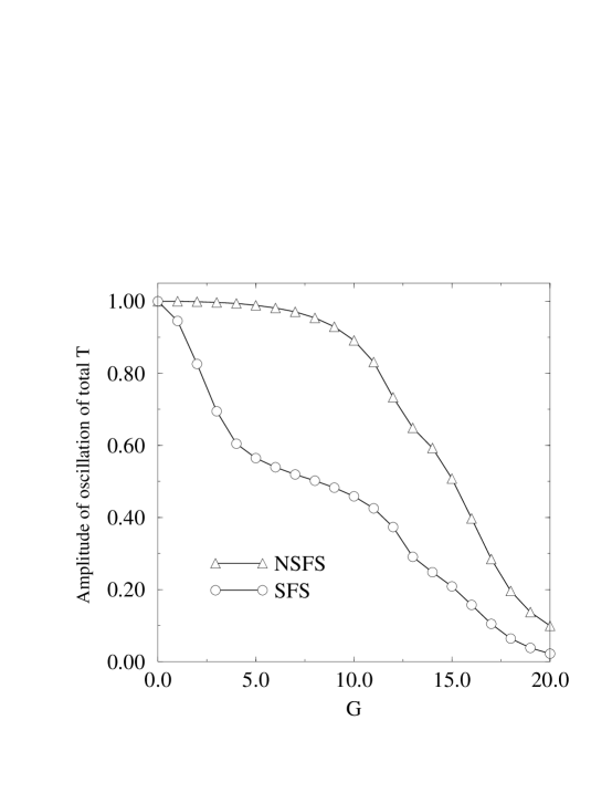
To quantify the decoherence, we calculate the amplitude of AB oscillations by taking the difference between the maximum and the minimum of total transmission coefficient as a function of flux over one period of the oscillation. A plot of the variation of the amplitude of oscillation of total transmission with the interaction strength for the two cases, no spin-flip scattering (NSFS: ) and spin-flip scattering (SFS: ), is shown in the figure Fig. 4. The signature of loss of interference is that the amplitude of AB oscillation of transmission coefficient for the spin-flip case is always smaller than that for the no spin-flip case for all non-zero values of coupling strength . In other words the reduction of amplitude of AB oscillations is stronger for the spin-flip scattering case. We have verified the above observation for other parameters in the problem. Thus the presence of spin-flipper reduces the AB-oscillations. This substantiates our claim of decoherence due to entanglement.
Now We will turn our attention to current magnification and associated effect of circulating currents as defined in earlier works[12, 13]. Fig. 5 shows the plot of circulating current density () versus for the two separate cases of spin-flip scattering and no-spin-flip scattering. When the impurity spin is “up” the interaction does not allow spin-flip for a spin-up incident electron and the impurity acts as a static potential scatterer. On the other hand when the impurity spin is “down” a spin-flip scattering takes place. We compare the circulating current densities for these two cases in order to see the role of entanglement induced by the spin-flipper. The solid curve is for the no-flip case while the dashed one is for the spin-flip case. The impurity strength () for both the cases is . In both the cases we take and . The figure shows that , the circulating current for spin-flip case is significantly less than that of the no-flip case in the range . Thus one is led to believe that the flipper acting as a dephasor suppresses the quantum phenomena of current magnification.
However, this naive expectation turns out to be incorrect. This is substantiated in Fig. 6 which shows circulating current densities for the spin-flip and no-flip cases in the range for the same lengths as mentioned above. From this figure we see that in this range of Fermi energies the amplitude of the circulating current is actually enhanced in spite of the spin-flip scattering.
Thus the flipper can not only suppress the current magnification effect but can also enhance it in some other range of Fermi energies. Thus far we have discussed how the flipper affects current magnification effect. The flipper also induces some new features. In Fig. 7 we have plotted circulating current density () versus for and in the range shows an additional peak in the circulating current density arising at a point corresponding to a minimum of spin-up transmission (which is same as the maximum of the spin-down transmission). This is indicative of the spin-flip process. This effect is unique for the flipper having no counterpart in case of a simple impurity, i.e., in this region () no-flip scattering case does not show any circulating current. This can be ascribed to the additional phase shifts caused by spin-flip scattering along-with multiple reflections. In the range spin-flip scattering suppresses the current magnification.
Further, we see another interesting feature, namely the phenomenon of current reversal. This is depicted in Fig.8. In this figure we plot the circulating current density () versus for and in the wave vector range in which we see that the spin-flip circulating current reverses its direction as compared to the no-flip case, i.e., an anti-clockwise circulating current for the no-flip case is converted into a clockwise one in the spin-flip case.
In conclusion we have shown that presence of the spin-flipper which reduces the AB oscillations(partial decoherence), need not reduce the amplitude of current magnification. In fact, in certain range of Fermi energies the flipper enhances the current magnification. We believe that the suppression of some quantum features and non-suppression of some other quantum effects is a characteristic feature of entanglement, environment consisting of finite degrees of freedom and the absence of inelastic scattering. We expect the same to happen in other models based only on the notion of entanglement. Only the presence of inelastic scattering(or coupling of a system to an environment with infinite degrees of freedom), leading to irreversible loss of phase memory, can dephase AB oscillations and reduce current magnification simultaneously. Our analysis on the same model shows that two probe spin-conductance is asymmetric in flux reversal as opposed to the two probe electrical conductance which is symmetric. Further case of a spin-flipper with higher number of internal states and that of flippers in both arms of the ring are under investigation. We hope that our results will stimulate further interest and understanding of dephasing and decoherence arising from different models based on quantum entanglement.
IV Acknowledgements
The author thanks Sandeep K. Joshi, Dr. D. Sahoo and Colin Benjamin for several useful discussions on this subject.
REFERENCES
- [1] E-mail: jayan@iopb.res.in
- [2] Y. Imry, Introduction to Mesoscopic Physics (Oxford University, New York, 1997).
- [3] S. Datta, Electronic transport in mesoscopic systems (Cambridge University Press, Cambridge, 1995).
- [4] P. S. Deo and A. M. Jayannavar, Pramana J. Phys. 56, 439 (2001).
- [5] S. Washburn and R. A. Webb, Adv. Phys. 35, 375 (1986).
- [6] Y. Gefen, Y. Imry, and M. Ya. Azbel, Phys. Rev. Lett. 52, 129 (1984).
- [7] A. M. Jayannavar and P. S. Deo, Phys. Rev. B 49, 13 685 (1994); P. S. Deo and A. M. Jayannavar, Phys. Rev. B 50, 11 629 (1994); and references therein.
- [8] A. Stern, Y. Aharonov and Y. Imry, Phys. Rev. A 41, 3436 (1990).
- [9] L. S. Schulman, Phys. Lett. A 211, 75 (1996).
- [10] D. Sprinzak, E. Buks, M. Heiblum and H. Shtrikman, Phys. Rev. Lett. 84, 5820 (2000) and references therein.
- [11] G. Prinz, Physics Today48, 58 (1995); Science 282, 1660 (1998) and references therein.
- [12] A. M. Jayannavar and P. S. Deo, Phys. Rev. B 51, 10 175 (1995);
- [13] T. P. Pareek, P. S. Deo and A. M. Jayannavar, Phys. Rev. B 52, 14 657 (1995).
- [14] Colin Benjamin, Sandeep K. Joshi, Debendranath Sahoo and A. M. Jayannavar, Mod. Phys. Lett. B in print (2001).
- [15] J-B. Xia, Phys. Rev. B 45, 3593 (1992).
- [16] O. L. T. de Menezes and J. S. Helman, Am. J. Phys. 53, 1100 (1985).
- [17] S. Das Sarma, J. Fabian, X. Hu, I. Zutic, Superlattices and Microstructures27, 289 (2000); I. Zutic and S. Das Sarma, Phys. Rev. B 60, 16 322 (1999).
- [18] M. Büttiker, IBM J. Res. Dev. 32, 317 (1988).