[
Very large dielectric response of thin ferroelectric films with the dead layers
Abstract
We study the dielectric response of ferroelectric (FE) thin films with “dead” dielectric layer at the interface with electrodes. The domain structure inevitably forms in the FE film in presence of the dead layer. As a result, the effective dielectric constant of the capacitor increases abruptly when the dead layer is thin and, consequently, the pattern of 180-degree domains becomes “soft”. We compare the exact results for this problem with the description in terms of a popular “capacitor” model, which is shown to give qualitatively incorrect results. We relate the present results to fatigue observed in thin ferroelectric films.
pacs:
77.22.Ch, 77.80.Dj, 84.32.Tt, 85.50.+k]
We have shown recently that the dead layer forming at the interface between ferroelectric (FE) thin film and electrodes has drastic effect on the electric response of a capacitor[1]. It has direct bearing on fatigue observed in FE capacitors since in many cases the deterioration of the switching behavior, like the loss of the coercive force and of the squareness of hysteresis loop, were attributed to the growth of a “passive layer” at the ferroelectric-electrode interface [2, 3, 4, 5]. It is of principal importance that the presence of a dead layer, no matter how thin in comparison with thickness of the ferroelectric layer, triggers a formation of the domain structure in FE film [1]. We have shown that when the thickness of the dead layer is not very small, the apparent (net) polarization of the ferroelectric with degree domain walls follows an approximate relation which is in good correspondence with available experimental data (see e.g. [6, 7] and references therein). Importantly, the response of this structure to an external bias voltage becomes more rigid when increases, i.e. when the dead layer grows, even in the absence of pinning by defects.
The implication for real systems is that with the growth of the passive layer the hysteresis loop very quickly deteriorates and looses its squareness, as observed. The approximate dependence of the response suggests that the effective dielectric constant of the capacitor
| (1) |
may become very large when the layer is thin. Here is the capacitance of the electroded FE film of area , with the separation between electrodes. Indeed, when the dead layer is thin, the domain width becomes very large, it grows exponentially with [1]. The response of this domain structure is very soft, and this should translate into very abrupt increase of the dielectric constant of the capacitor. It is easy to show that in the present case (180o domains) the linear response is not changed by electromechanical effect, the change in only appearing in quadratic terms in external field, but here we are interested in zero-field value of only. We have assumed a quadratic coupling between the elastic strains and the polarization (as in perovskites). In this case the linear response of 1800 domain structure without pinning is not affected by intimate contact between the ferroelectric and the dead layer (excluding mere renormalization of materials constants by homogeneous stresses). Note that this is invalid in the case of 90o domains [8] or a linear coupling between the strain and the polarization[9].
Here we address the anomalous behavior of the dielectric constant in detail. We also discuss the important issue regarding the relation of the present results to so-called “capacitor” model [3, 4, 6]. The “capacitor” model (incorrectly) presumes that the dielectric response of the dielectric layer is not affected by the presence of the dead layer, so the system looks like capacitances in series. We show that the effective “dielectric constant” of the FE layer, , as found in the “capacitor” model[3, 4, 6], is actually negative. In spite of this the system remains stable (stiffness of the domain pattern is positive).
The reason for this apparently unusual behavior () is that the “dielectric constant” of the FE layer is the non-local quantity which characterizes the whole system. This non-local behavior is due to long range Coulomb interaction, which makes the response rigid even when the FE itself would have a negative “dielectric constant” (cf. Ref. [10], Fig. 1). The “capacitor” model neglects this essentially nonlocal behavior and, therefore, is hardly applicable to the problem of dielectric response of thin ferroelectric films, and to the problem of fatigue for that matter. The present considerations remain valid until the period of the domain structure remains much smaller that the lateral size of the film (or the grain size). Those will set some cutoff for the effects considered below.
We shall find the response of a ferroelectric film under a bias voltage with thickness separated from the top and bottom electrodes by passive layers with thickness (Fig. 1, inset) with the use of the thermodynamic potential[1]:
| (2) | |||||
| (3) |
Here is the surface energy of the domain walls, is the electrostatic energy, is the electric field, while ( is the charge (potential) on the electrode The last term in Eq. (3) accounts for the work of the external voltage source(s). Note that the results would not change qualitatively is there were only one dead layer, since the accompanying depolarizing field would have the same effect.
We are interested in a case when the ferroelectric has the spontaneous polarization (Fig. 1, inset), i.e. we are considering the case of degree domain walls. The uniaxial ferroelectric film has the dielectric constant ( in the -direction (in the -plane), and the dielectric constant of the passive layer is We select the -axis perpendicular to the domain walls. The potential which is related to the electric field in usual way, , satisfies the following equations of electrostatics in the ferroelectric and the passive layer[1],
| (4) |
with the boundary conditions , and
| (5) |
where the subscript ( denotes the ferroelectric (passive layer, or a vacuum gap). Here is the density of the bound charge due to spontaneous polarization at the ferroelectric-passive layer interface, , depending on the normal direction of the polarization at the interface, alternating from domain to domain, Fig. 1 (inset). Thus, we assume that the absolute value of the spontaneous part of the polarization is constant in all domains and only its direction is alternating from domain to domain. We have also assumed a usual separation of linear and spontaneous polarization, so that the displacement vector is , where , and the dielectric response in uniaxial, Fig. 1(inset). Within this approximation we obtain
| (6) |
where is the density of the bound charge given by only the spontaneous polarization at the interfaces between the FE and the dead layer, and the integration goes over these interfaces. The periodic pattern consists of domains with widths and , and the period . The solution of the equations (4) is then readily found by Fourier transformation
| (7) | |||||
| (8) | |||||
| (9) |
where , and the index marks the quantities for the FE layer and the dead layer. Note that by definition is the net spontaneous polarization of the FE layer. We obtain
| (10) | |||||
| (11) | |||||
| (12) |
where
| (13) |
and
| (14) |
is the net charge density induced on the electrode at , with the area of the film. One can calculate the apparent dielectric constant of the whole capacitor from
| (15) |
The term in Eq. (10) is due to the net polarization of the FE film induced by the bias voltage , with the first term in (11) corresponding to the term , singled out in the stray field energy 12 With the use of from (8) we obtain
| (17) | |||||
where
The total free energy of the domain pattern per unit area is
| (18) |
where is the surface energy of the domain wall, with the characteristic microscopic length[1]. This free energy allows one to determine the equilibrium properties and response of the domain pattern to external field.
We can determine a linear response of the system to bias voltage from the total energy (18), which, for small bias can be expanded up to terms quadratic in and
| (19) |
where , is the usual stray energy, , given by the first term in Eq. (17). This expression results from expanding the Eqs.(12),(17) in powers of and (note that Here is the stiffness of the domain structure with respect to external bias voltage [we have omitted the constant term in Eq. (19)]. We have
| (20) | |||||
| (21) | |||||
| (22) |
where is the (negative) contribution of the inhomogeneous (stray) energy, corresponding to the second term in (17),
| (23) |
We can now consider the following limiting cases:
Thick dead layer ( There we can replace both in (13) by unity, with the result
| (24) |
with The domain structure has a minimum energy for the equilibrium (Kittel) domain width
| (25) |
so that , a usual relation. Then inhomogeneous contribution to stiffness Eq.(23), and we obtain from Eqs.(21),(22)
| (26) |
When one can neglect the second (stray) term in this expression for stiffness, thus recovering our approximate expression for the net spontaneous polarization of the ferroelectric film from (19) [1]
| (27) |
This approximation breaks down for thinner films but it is obvious that the response becomes softer for thinner dead layers. The breakdown of this approximate behavior has also been noticed by Kopal et al. for similar model[11], but they have not analyzed what actually happens to the response at very small thicknesses of the dead layer. Note that Eq. (23), and, consequently, the following inequality always holds: .
Thin dead layer (In this case the replacement of by unity is not allowed. For and we have and
| (28) | |||||
| (29) |
where [12]. By using the asymptotic expansion of we obtain for our earlier result[1]
| (30) |
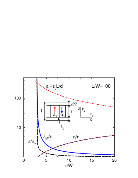
which corresponds to very abrupt increase of the domain width to values with the Kittel width (25), when the dead layer is very thin, Fig. 1. This approximation, however, is not sufficient to make an estimate of the stiffness for very thin dead layers. Indeed, formally the stiffness there becomes small and negative, . This fact simply indicates that for thin dead layers the stiffness diminishes, and has to be calculated more accurately. The exact results, illustrating the abrupt softening of the dielectric response for small are shown in Fig. 1.
One may wish to interpret the approximate result for slope of the net polarization given by Eq.(27), in terms of the “capacitors in series” model [3, 4, 6]. Indeed, a similar result follows if one were to assume that the capacitance of the dead layer, dominates at small thicknesses of the layer
An opinion has even been voiced that the effective dielectric constant of the FE layer is infinite (?) since the domain walls in our model are not pinned [13]. However, such an interpretation would be incorrect since , as found in the “capacitor” model, is not infinite, but finite and actually negative. To establish this, one has to find the voltage drops across the dead layer and FE film. The homogeneous part of the electric fields inside the FE (dead) layer and the corresponding voltage drops are found from the standard equations
| (31) | |||||
| (32) |
where from one can, for instance, easily recover the expression (14) for the net charge density on electrodes. One obtains the “capacitor” model by assuming that the interface between the FE film and the dead layer is equipotential and can be viewed as the metallic film separating two areas. Simple calculation gives
| (33) | |||||
| (34) |
where Since always Eq. (27), we obtain Fig. 1. In spite of formally negative “dielectric constant” of the ferroelectric layer Eq.(33), which is an artifact of the “capacitor” model [3, 4, 6, 13], the system remains stable (stiffness of the domain pattern is positive). Indeed, shifting the domain walls would create a net electric field in the capacitor, see Eq. (11) and second term in Eq. (19), and its energy is the source of finite stiffness of the domain pattern, even when the walls are not pinned, as is very well known since 1960 [14].
The reason for this apparently unusual behavior () is that the “dielectric constant” of the FE layer in (33) is the non-local quantity which characterizes the whole system: it depends on the properties of the dead layer. This non-local behavior is due to long range Coulomb interaction, which makes the response rigid even when the FE itself would have a negative “dielectric constant” (for analogous situation in FE films with depletion charge see Ref. [10], Fig. 1). Thus, the “capacitor” model actually operates with obscure quantities without much physical meaning.
We illustrate the difference between the exact results for and that following from the “capacitor” model in the assumption [13] in Fig. 1. The softness of the domain structure, characterized by increases very abruptly when the dead layer is thin and the width of the domains is [Kittel width (25)]. According to (34), increases abruptly and becomes in this region, Fig. 1, in stark deviation from the prediction of the “capacitor” model [13]. For thick “dead layers” the effective dielectric constant becomes comparable to , as we showed earlier[1].
We think that the above clearly demonstrates a danger of applying a naive electric circuit analysis to FE systems where the addition of one “circuit element” (dead layer) radically changes the electric response of the other, FE layer, by introducing a domain structure. It is not surprising, therefore, that such an approach cannot explain a fatigue observed in FE films (see e.g. [6, 7] and references therein). Certainly, there might be various reasons for the fatigue in FE capacitors. We simply observe that the growth of the dead layer at the interface with electrode makes the dielectric response of the film rigid even when the domain walls are not pinned. The present mechanism gives a correct order of magnitude for the tilt of the hysteresis loops[1], therefore the growth of passive layer might be the main source of fatigue. In the limiting case of thin dead layers the period of the ferroelectric domains in the absence of pinning becomes much larger than the standard Kittel width. As a consequence, the domain pattern becomes very “soft” in the absence of the pinning of the domain walls, and its contribution to the dielectric response becomes very large, since the domains with polarization parallel to the external field can easily grow at the expense of the domains with the opposite polarization.
REFERENCES
- [1] A.M. Bratkovsky and A.P. Levanyuk, Phys. Rev. Lett. 84, 3177 (2000).
- [2] M.E. Drougard and R. Landauer, J. Appl. Phys. 30, 1663 (1959).
- [3] S.L. Miller, R.D. Nasby, J.R. Schwank, M.S. Rodgers, and P.V. Dressendorfer, J. Appl. Phys. 68, 6463 (1990).
- [4] J.J. Lee, C.L. Thio, and S.B. Desu, J. Appl. Phys. 78, 5073 (1995).
- [5] V.V. Lemanov and V.K. Yarmarkin, Phys. Sol. State 38, 1363 (1996) [Fiz. Tverd. Tela 38, 2482 (1996)].
- [6] A.K. Tagantsev, M. Landivar, E. Colla, and N. Setter, J. Appl. Phys. 78, 2623 (1995).
- [7] A. Gruverman, O. Auciello, and H. Tokumoto, Appl. Phys. Lett. 69, 3191 (1996).
- [8] N.A. Pertsev and V.G. Koukhar, Phys. Rev. Lett. 84, 3722 (2000).
- [9] A.M. Bratkovsky and A.P. Levanyuk, cond-mat/0010098 (2000).
- [10] A.M. Bratkovsky and A.P. Levanyuk, Phys. Rev. B 61, 15042 (2000).
- [11] A. Kopal, O. Mokry, J. Fousek, and T. Bahnik, Ferroelectrics 223, 127 (1999).
- [12] , see I.S. Gradshteyn and I.M. Ryzhik, Table of Integrals, Series, and Products, 5th ed., edited by A. Jeffrey (Academic, New York, 1994), Sec. 9.55.
- [13] A.K. Tagantsev (unpublished).
- [14] C. Kooy and U. Enz, Philips Res. Repts. 15, 7 (1960). Those authors gave a transcendental equation for magnetization versus magnetic field, for a slab of ferromagnetic material in terms of some series, which was evaluated numerically. Note that the effects of screening of electric field by electrodes, which are responsible for the present unusual behavior of the domain pattern in ferroelectric capacitor, have no analogy in magnetic systems.