Single-electron soliton avalanches in tunnel junction arrays
Abstract
Numerical modeling of correlated single-electron tunneling in uniform 2D arrays of small conducting islands separated by tunnel junctions shows the possiblility of soliton-antisoliton avalanches. Though the time duration of any avalanche, and the total charge transferred across the array during the avalanche, are always finite, in arrays with length larger than certain critical value and large width , the avalanche magnitude may be exponentially large, resulting in particular in a giant increase of shot noise. Thermal fluctuations and disorder gradually suppress the avalanche effect.
PACS numbers: 72.70+m, 73.23.Hk
During the past few years, there was much interest in correlated single-electron transport [1, 2] in large arrays of small conducting islands separated by tunnel barriers - see, e.g., Refs. [3, 4, 5, 6, 7, 8, 9, 10, 11, 12, 13, 14, 15, 16, 17, 18, 19, 20, 21, 22] and references therein. This attention is due to several interesting properties of the arrays, the most basic of which is the existence of single-electron solitons [3, 6]. Such a soliton consists of an additional single-electron charge placed on an island of the array, surrounded by a group of totally neutral but strongly polarized islands which screen the electron field at large distances. Similarly, removal of an electron from a single island creates an “antisoliton” (i.e., a single-hole soliton).
The concept of single-electron solitons and antisolitons and their interaction allows a natural explanation of all the peculiarities of the array statistics and dynamics, including the Kosteritz-Thouless-like phase transition in the 2D case [6, 7, 14], single-electron oscillations of frequency [4, 5, 13], Coulomb drag [9, 16], effects of disorder [12, 17, 18, 20], and shot noise suppression [21, 22]. The goal of this Letter is to report the prediction of a new phenomenon in 2D SET arrays: soliton/antisoliton avalanches which lead to shot noise enhancement rather than suppression.
We have obtained theoretical evidence of this effect during Monte Carlo simulation of 2D array dynamics within the “orthodox” model of single-electron transport [1]. In this model, which is quantitatively valid when the tunnel conductances between the array islands are sufficiently low (), single electron tunneling events are treated as incoherent transitions with rates
| (1) |
where is the drop of the electrostatic free energy caused by the particular transition. The energy of a charge configuration was calculated within the usual approximation [3, 6] (strictly correct for an array sufficiently close to a conducting ground plane) in which the capacitance matrix includes only diagonal terms and near-diagonal terms which represent island self-capacitances and mutual capacitances between the neighboring islands, respectively. We studied not only the average current through the array, but also the spectral density of current fluctuations.
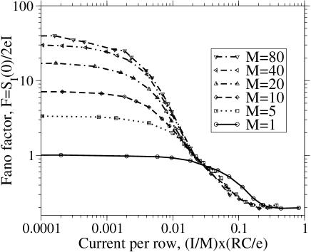
The results show that at larger currents the Fano factor decreases to 1/ ( is the longtitudinal number of junctions), just as in 1D arrays [21], so that the low-frequency shot noise is indeed suppressed in comparison with the Schottky value . However, rather unexpectedly, we have found that in uniform arrays at low temperature and low currents (near the Coulomb blockade threshold) the Fano factor may be much larger than one - see, e.g., Fig. 1.
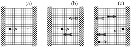
This fact invites the suggestion that electrons are transferred through the array in “bundles” with total charge ; however, since single-electron solitons repel [3, 4], the mechanism of the bundle formation was not immediately clear. The solution to this puzzle has turned out to be very simple. It is illustrated by Fig. 2 which shows a few snapshots of a typical Monte-Carlo-simulated process at zero temperature, when the dc voltage applied to the array is just slightly (in this particular case, by ) above the Coulomb blockade threshold . At , the soliton entrance into the initially empty array is the main transport sequence bottleneck, and takes place only after a considerable time pause when the array is free of any extra charges. After the entrance from one electrode, the soliton starts to drift, hopping along the electric field applied to the array (Fig. 2a). When the soliton approaches the opposite electrode, its field may induce the entrance of one or more antisolitons, i.e. single-hole solitons (Fig. 2b). After these antisolitons have passed their transport bottleneck at the entrance, they drift mostly along the applied electric field (in the direction opposite to that of the soliton), the attracting field of the initial soliton having little effect on the drift. Because of this, soliton-antisoliton pairs frequently miss their chance to recombine, though lateral tunnel junctions between island rows allow such recombination and we do observe such events in our simulation. In turn, each antisoliton approaching the array electrode may trigger the entrance of one or more solitons (Fig. 2c), This chain reaction results in a soliton-antisoliton avalanche, very much similar to an electric discharge in a gas due to surface impact ionization [23]. Notice that in 1D arrays the soliton and antisoliton cannot pass each other, so that the recombination always happens; as a result avalanches are absent and [21].
Due to the stochastic character of transport within the framework of the orthodox theory, there is always a chance that every soliton and antisoliton leaves the array without triggering the entrance of any solitons of the opposite charge. Because of this, the avalanches always have a finite duration in time and finite “magnitude” (the latter may be defined by the equation for the total charge transferred through the array during one avalanche). Nevertheless, the avalanches may be rather large: in wide arrays we have observed ’s up to , limited only by the computer simulation time.
In the range where avalanches are distinct, computation of may be sped up considerably by using formulas for “charge blocks”, which were derived in Ref. [24] (in a different context):
| (2) | |||
| (3) |
If avalanches do not overlap, is just the magnitude of a single avalanche, while is the interval between the beginnings of the adjacent avalanches. In the particular case , Eqs. (2) and (3) yield
| (4) |
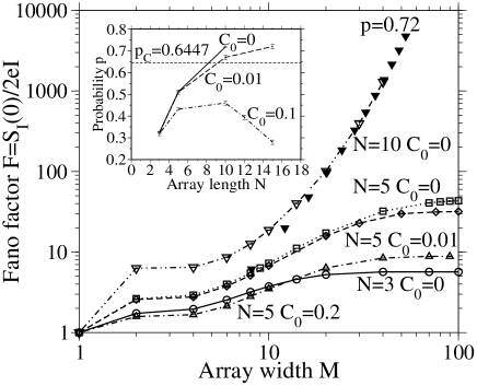
Figures 1 and 3 show the dependence of on the main parameters of the system: array length , width , island capacitance ratio , and applied voltage [the last dependence is presented parametrically via the induced dc current ]. Most of these dependences may be readily understood, at least qualitatively, using the avalanche picture discussed above. For example, if the ratio is increased, the soliton radius decreases [3, 6], so that the soliton-antisoliton interaction is quenched, and is decreased. Larger gives the soliton more time to induce solitons of the opposite sign, so that grows. Finally, in very narrow arrays (small ) the soliton-antisoliton recombination suppresses the avalanche magnitude, so that the Fano factor also decreases.
We have found that the avalanche statistics dependence on in the opposite limit of large may be understood as follows. In wide arrays, the probability that a soliton triggers the entrance of an antisoliton, and does not recombine with it, should not depend much on the array width . The average number of rows separating the soliton and the neighboring antisoliton, may depend on and , but should be also virtually independent of . This is why we may introduce an approximate “macromodel” which is schematically shown in the inset of Fig. 4: an array of width is presented as a parallel connection of channels of equal width . We break the avalanche into time stages of equal duration and assume that a passage of a soliton in some channel at stage triggers the antisoliton passage in each of the two neighboring channels at stage with probability . The lateral (open) sides of the array are described by setting the corresponding probability to 0. Mathematically, our macromodel is exactly the problem of the directed bond percolation problem on a 2D square lattice [25] within a stripe of width .
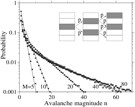
Despite the approximate character of the macromodel, it allows the results of the initial problem to be reproduced remarkably well. For example, Fig. 4 shows avalanche amplitude histograms (probability to find an avalanche with particular magnitude ) for 5 arrays of different widths. The Monte Carlo simulation results virtually coincide with the macromodel results, despite only two parameters ( and ) were available for fitting all 5 curves. (An equally good fit was obtained for all other values of and we have studied if was large enough, .) At the same time, the macromodel is much faster for simulation, so that with the same computer resources, results may be obtained in a much broader range of array parameters. For example, open points in Fig. 3 show Monte Carlo results for the initial model; for , we could hardly get acceptable accuracy at . For the macromodel described above, calculation of in that point (with the same error bars) took 35 times less CPU time, and we could continue calculations all the way up to = 55 (closed triangles).
The macromodel also gives a clear explanation why the growth of the avalanche magnitude with array width saturates for shorter arrays, but is unbound for longer arrays (Fig. 3). The directed bond percolation problem on square lattice has a percolation threshold , beyond which there is a finite probability of having an infinite percolation cluster on an infinite lattice. We have found that for our problem, becomes larger than if the array length is above a certain value . ( for , and grows with the increase of the ratio; for large enough , never reaches at all – see inset in Fig. 3.) This means that at and unlimited there is a finite probability of having an infinite avalanche which, once started, would never end. The large, but finite, array width (and hence a large but finite ) stops the avalanche growth in time, and limits its magnitude at a finite (though exponentially large in ) level.
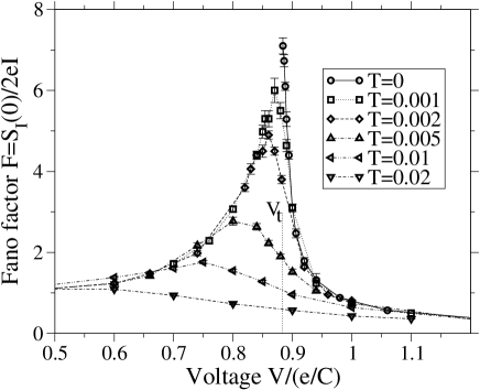
The avalanche effect is most strongly expressed in uniform arrays at zero temperature, while both thermal fluctuations and array disorder gradually suppress it. Figure 5 shows a typical dependence of the Fano factor on the applied voltage for several values of temperature. For , transport is possible only above the Coulomb blockade threshold , so that below this point is undetermined. However, even very small temperature fluctuations reveal the second branch of this dependence, since the initial energy barrier for soliton entrance to the array may be overcome by thermal activation, so that dc current becomes finite (though may be very small). Figure 5 shows that for , the Fano factor decreases as applied voltage is decreased, approaching 1 for smaller . The reason for this decrease is that as , it is harder and harder for the initial soliton to trigger the antisoliton entrance, so that single-soliton passages become the dominant component of transport. (At very small voltages, , the Fano factor starts to grow again as due to quasi-equilibrium thermal fluctuations. However, in our case of low temperatures, , this growth corresponds to exponentially low dc current.) Larger temperature leads to gradual de-correlation of the moments when solitons and antisolitons enter the array, and hence to a gradual suppression of the avalanches which depend on this correlation.
The effect of disorder is qualitatively similar (in qualitative agreement with the results for the directed bond percolation [26]). For example, in a junction array with , the introduction of background charges to just 6 percent of the islands at random usually suppresses avalanches completely, reducing to 1.
To summarize, we have found strong theoretical evidence for (and a simple explanation of) a new effect of single-electron-soliton and antisoliton avalanches in 2D arrays of small conducting islands. This effect arises due to soliton-assisted entrance of antisolitons into neighboring, but different rows of the array, thus avoiding recombination. The basic physics of the effect is well captured by a simple “macromodel”, equivalent to the directed percolation model on a square-lattice strip of finite width. Thermal fluctuations and array disorder suppress the avalanches. Presently, we are working toward a quantitative characterization of the latter suppression, in particular with the goal to evaluate feasibility of experimental observation of the soliton avalanches using various techniques of array fabrication [5, 7, 14, 15, 19, 20]. Apparently, this may be easier to accomplish in an array with tunnel-uncoupled rows (essentially, a generalization of the 2-row system studied earlier [9, 16]), where tuning of dc voltages applied to each row may be sufficient to compensate for a moderate disorder.
The work was supported in part by the Engineering Research Program of the Office of Basic Energy Sciences at the Department of Energy.
REFERENCES
- [1] D.V. Averin and K.K. Likharev, in Mesoscopic Phenomena in Solids, ed. by B. Altshuler et al. (Elsevier, Amsterdam, 1991), p. 173.
- [2] Single Charge Tunneling, ed. by H. Grabert and M.H. Devoret (Plenum, New York, 1992).
- [3] K.K. Likharev, IBM J. Res. Devel. 32, 144 (1988).
- [4] N.S. Bakhvalov, G.S. Kazacha, K.K. Likharev, and S.I. Serdyukova, Sov. Phys. JETP 68, 581 (1989).
- [5] P. Delsing, K. Likharev, L. Kuzmin, and T. Claeson, Phys. Rev. Lett. 63, 1861 (1989).
- [6] U. Geigenmüller and G. Schön, Europhys. Lett. 10, 765 (1989).
- [7] J.E. Mooij, B.J. Van Wees, L.J. Geerligs, M. Peters, R. Fazio, and G. Schön, Phys. Rev. Lett. 65, 645 (1990).
- [8] N.S. Bakhvalov, G.S. Kazacha, K.K. Likharev, and S.I. Serdyukova, Physica B 173 581 (1991).
- [9] D.V. Averin, A.N. Korotkov, and Yu.V. Nazarov, Phys. Rev. Lett. 66, 2818 (1991).
- [10] P. Delsing, in Single Charge Tunneling, (Ref. 2), p.249.
- [11] J.E. Mooij, G. Schön, in Single Charge Tunneling, (Ref. 2), p. 275.
- [12] A.A. Middleton and N.S. Wingreen, Phys. Rev. Lett. 71, 3198 (1993).
- [13] A.N. Korotkov, Phys. Rev. B 50, 17674 (1994).
- [14] S. Kobayashi, A. Kanda, and R. Yamada, Jpn. J. Appl. Phys. 34, 4548 (1995).
- [15] R.P. Andres et al., Science 273 1690 (1996).
- [16] P. Delsing, D.B. Haviland, and P. Davidsson, Czech. J. Phys. 46, 2359 (1996).
- [17] A.N. Korotkov, unpublished (1996); see Fig. 13 in K. Likharev, Proc. IEEE 87, 606 (1999).
- [18] J.A. Melsen, U. Hanke, H.-O. Müller, and K.-A. Chao, Phys. Rev. B 55, 10642 (1997).
- [19] A.S. Cordan, A. Goltzene, and H. Launois, J. Appl. Phys. 84 3756 (1998).
- [20] C. Kurdak, A.J. Rimberg, T.R. Ho, and J. Clarke, Phys. Rev. B 57, R6842 (1998).
- [21] K.A. Matsuoka and K.K. Likharev, Phys. Rev. B 57, 15613 (1998).
- [22] See Appendix in A.N. Korotkov and K.K. Likharev, Phys. Rev. B 61, 15975 (2000).
- [23] See, e.g., R.W. Crompton, Gaseous Electronics and its Applications (Kluwer, Dordrecht, 1991).
- [24] A.N. Korotkov, Phys. Rev. B 49, 10381 (1994).
- [25] See, e.g., Percolation Structures and Processes, ed. by G. Deutsher et al. (Hilger, Bristol, 1983).
- [26] A.J. Noest, Phys. Rev. Lett. 57, 90 (1986).