Spin-splitting in GaAs 2D holes
Abstract
We present quantitative measurements and calculations of the
spin-orbit induced zero-magnetic-field spin-splitting in
two-dimensional (2D) hole systems in modulation-doped GaAs (311)A
quantum wells. The results show that the splitting is large and
tunable. In particular, via a combination of back- and front-gate
biases, we can tune the splitting while keeping the 2D hole
density constant. The data also reveal a surprising result
regarding the magnetoresistance (Shubnikov-de Haas) oscillations
in a 2D system with spin-split energy bands: the frequencies of
the oscillations are not simply related to the population of
the spin-subbands. Next we concentrate on the metallic-like
behavior observed in these 2D holes and its relation to
spin-splitting. The data indicate that the metallic behavior is
more pronounced when two spin-subbands with unequal populations
are occupied. Our measurements of the magnetoresistance of these
2D hole systems with an in-plane magnetic field corroborate this
conclusion: while the system is metallic at zero magnetic field,
it turns insulating when one of the spin-subbands is depopulated
at high magnetic field.
Keywords: GaAs 2D
holes, Spin-subbands, mobility anisotropy, 2D metal-insulator
transition
I Introduction
Zero-magnetic-field () spin-splitting of energy bands has long been a subject of considerable experimental and theoretical effort because of its role in the electronic properties of two-dimensional (2D) systems [1, 2, 3]. It concerns details of energy band structure that are of fundamental interest. The eigenstates in a system that has inversion symmetry in both space and time are spin-degenerate. If the system is made spatially inversion asymmetric, this degeneracy is lifted by spin-orbit interaction for all momentum , even in the absence of an external magnetic field. In 2D systems, we can create this spatial inversion asymmetry simply by making the potential which confines the carriers to 2D asymmetric.
In this work, we study the spin-splitting in GaAs 2D holes confined to a quantum well (QW) grown on the (311)A surface of a GaAs substrate. Section II provides some experimental details. In Section III, we show that by using two gates on the back and front of the sample to control the electric field applied perpendicular to the QW, the asymmetry and therefore the spin-splitting can be tuned while the carrier density is kept constant. In the process we discover that the low- Shubnikov-de Haas oscillations are not as simply related to the spin-splitting as has often been presumed [4].
Tuning the spin-splitting without changing the density allows us to isolate the effect of spin-splitting on various phenomena. In recent years there has been significant interest in the surprising metallic behavior of various high-quality 2D systems [5, 6, 7, 8, 9, 10, 11, 12, 13, 14, 15, 16, 17, 18, 19, 20]. In Section IV we show the effect of spin-splitting on the metallic behavior of the 2D holes in GaAs [12, 13].
Finally, motivated by recent theoretical predictions [21, 22], we have applied an in-plane to these samples and studied the magnetoresistance (Section V). We have found that, remarkably, the in-plane depopulates the upper spin-subband at a rate which depends on the relative orientations of and the crystal axes! This is a reflection of the anisotropic band structure and Zeeman splitting in the system. Furthermore, when the upper spin-subband is depopulated, the metallic behavior turns to insulating behavior. We also see an in-plane magnetoresistance anisotropy that depends on the relative orientations of and the current ; the finite layer thickness of our 2D system may be responsible for this observed anisotropy [22].
II Experimental
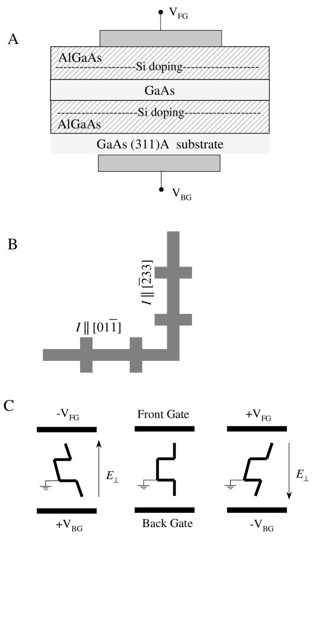
A schematic cross section of our samples is shown in Fig. 1A. The samples are grown, via molecular beam epitaxy (MBE), on GaAs (311)A substrates. Each sample contains a 20 nm-wide GaAs QW flanked by AlGaAs barrier layers which are modulation doped with Si. On GaAs (311)A substrates, Si is normally incorporated as an acceptor, leading to a high-quality 2D hole system in the GaAs QW. We make ohmic contacts to the 2D holes using In:Zn and alloying in a reducing atmosphere. As shown in Fig. 1A, our samples have back and front gates to change the density of the 2D hole system and also tune the symmetry of the confining QW potential. The back gate is made by contacting a layer of In left over on the back of the substrate from the MBE growth, and the front gate is evaporated metal (Ti-Au).
GaAs 2D systems grown on (311)A substrates have an intrinsic mobility anisotropy due to an anisotropic interface roughness [23, 24]. The mobility for current along the direction can be up to several times the mobility for current along the direction. For this reason, we did our measurements on -shaped Hall bars, which allow simultaneous measurement of the resistivity for current along these two directions (Fig. 1B).
Measurements were done in dilution and 3He refrigerators, with base temperatures of 30 mK and 0.3 K respectively. The systems are fitted in a superconducting magnet capable of magnetic fields up to 16 T. The 3He refrigerator has a tilting stage for the sample that can be rotated in-situ, so the relative angle between the magnetic field and 2D hole system plane can be varied.
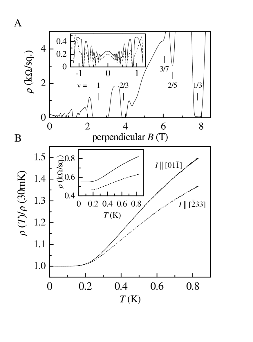
Figure 2 shows an example of data for one of the samples from both mobility directions, measured simultaneously at 30 mK . The inset to A shows the low- data. The main part of A demonstrates the high quality of the sample. The inset to B shows raw -dependence of data, and the main part of B shows it scaled to , the resistivity at 30 mK.
III Tuning Spin-splitting
We use the gates to tune the asymmetry of the QW by applying an electric field () perpendicular to its plane. Figure 1C schematically demonstrates the procedure. We set the front gate () and back gate () voltages, and measure as a function of . Then, at a small , is increased and the change in the hole density is measured from the change in the Hall coefficient. is then reduced to recover the original density. This procedure changes while maintaining the same density to within 3%, and allows calculation of the change in from the way the gates affect the density. These steps are repeated until we have probed the range of and that are accessible without causing gate leakage [12]. Increasing the magnitude of increases the asymmetry of the sample, which increases the spin-splitting.
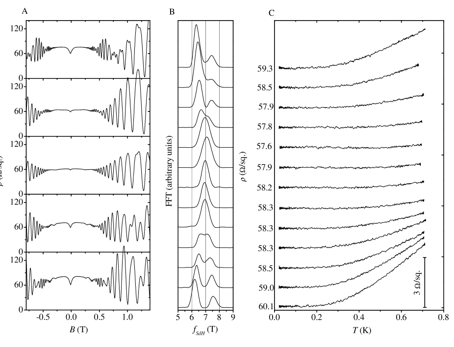
Figure 3A shows examples of the Shubnikov-de Haas (SdH) oscillations measured for current along the direction in our 20 nm QW, following the procedure described above to change from about 5 kV/cm (pointing towards the front gate) in the top panel through to about -6 kV/cm in the bottom panel. Beating can be clearly seen in the oscillations of all traces except the center trace where . Fast Fourier transforms (FFTs) of vs. quantify the frequencies present. Figure 3B shows the FFTs of the SdH oscillations at all of the measured sets of and . These frequencies have long been thought to be directly proportional to the spin-subband densities () following [1, 2]:
| (1) |
With this interpretation it is clear in Fig. 3B that we are tuning the spin-splitting through a minimum as we change from 5 kV/cm to -6 kV/cm: the two peaks, corresponding to two spin-subband densities, get closer together as approaches zero, finally merging, only to separate again as is decreased away from zero. Below, we show that Eq. 1 is only approximately true.
In order to compare the theory of spin-splitting to the experimental results, we have performed self-consistent subband calculations that have no adjustable parameters (further details are in Refs. [2] and [4]). These calculations produce, for a given 2D hole density and , both the spin-subband densities and the SdH oscillations. It is important to note that both of these results are produced by the same Hamiltonian, so they are directly comparable. These calculations yield a surprising result: FFTs of the calculated SdH oscillations show that the frequencies present, when converted to spin-subband densities using Eq. 1, do not agree with the calculated spin-subband densities [4].
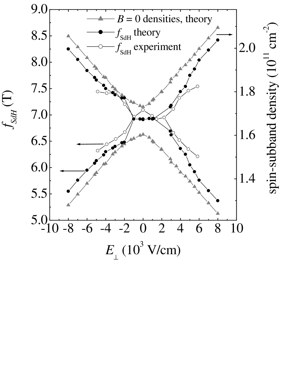
This is highlighted in Fig. 4 which shows the calculated spin-subband densities (right axis), and the peak positions of FFTs () of both the calculated and measured SdH oscillations (left axis), as a function of [25]. The two -axes of the figure are scaled by Eq. 1, so the sets of data can be directly compared. The calculated consistently underestimate the spin-splitting. The agreement between the theoretical and measured , however, is very good. Especially noteworthy are the results for . As the calculations in Fig. 4 indicate, even at , there should be finite spin-splitting because of the inversion asymmetry of the GaAs (zincblende) crystal structure. However, both the measured and calculated FFTs show only one peak for kV/cm [26].
We believe that the inaccuracy of Eq. 1 is due to a breakdown of Onsager’s argument [27], which is based on Bohr-Sommerfeld quantization of the semiclassical motion of the Bloch carriers. The presence of spin-orbit interaction makes the system inherently quantum-mechanical, so a semiclassical picture fails. This finding is quite general in that one can expect deviations from a semiclassical picture for all systems with strong spin-orbit interaction. However, the full quantum-mechanical calculations predict that Eq. 1 can be quite accurate for some 2D systems grown on high-symmetry crystal directions, while being inaccurate for other crystal directions or other systems [4].
IV Metallic behavior and spin-splitting
For many years, it was widely accepted that there can be no metallic phase in a 2D carrier system [28, 29]. However, recent experiments on several different high quality 2D systems have provided us with reason to re-visit this belief, as they showed that has a metallic-like temperature dependence: at very low temperatures decreases with decreasing [5, 6, 7, 8, 9, 10, 11, 12, 13]. Various mechanisms [30, 31, 32, 33] have been proposed to explain the metallic behavior, but no clear model has emerged which quantitatively describes the sizeable body of experimental data.
By tuning the spin-splitting at constant density, we isolate the effect of spin-splitting on the -dependence of [12, 13]. Figure 3C shows as a function of for each of the measured . The traces are lined up with the corresponding FFTs in Fig. 3B. From this data it is evident that the magnitude of the change in from 30 mK to 0.7 K is correlated with the spin-splitting. The 30 mK, resistivity () for each trace is listed on the -axis.
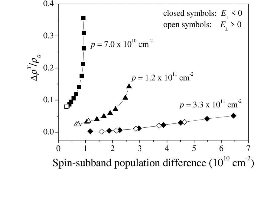
In order to characterize the -dependence data in a simple way, we calculate , the fractional change in resistivity from 30 mK to 0.7 K. This is plotted in Fig. 5 vs. the spin-subband population difference calculated at (). We have repeated this type of experiment on lower density samples, down to a density of cm-2. For densities from to cm-2, for which the vs. traces have qualitatively the same shape as in Fig. 3C, we have calculated the spin-subband densities. As shown in Fig. 5, data for these densities exhibit the same trend: is larger at larger , and is more sensitive to spin-splitting at the lower measured densities.
The -dependence of for a density of cm-2 has a qualitatively different shape from the higher-density data: it exhibits a local maximum. Increasing moves this local maximum to lower . We note that previous experiments on the density-dependence of the metallic behavior show that at high densities monotonically increases with , and that as the density is reduced and the transition to insulating behavior is approached, a local maximum appears in vs. [5, 9, 10, 11]. Qualitatively, in the density range we have measured, the effect of increasing spin-splitting on shape of vs. is similar to the effect of reducing density.
For the highest density, cm-2, we have direct experimental support for the calculated . At the lower densities the sample quality is typically worse and the spin-splitting is too small so that two frequencies are not resolved in the SdH oscillations. We use the calculations described in Section III to determine the expected used in Fig. 5 from the . Even if a large error in is allowed for, the conclusions of the previous paragraphs are still valid.
Tuning tunes the spin-splitting, but can also affect the mobility and cause changes in . However, a careful examination of all our data reveals that the changes in are not causing the changes in . The variation of due to does not correlate with the changes in . One example of this is in Fig. 3C, where there are three traces at different that have different , but the same (58.3 /sq.).
All of the data we have presented so far have been from the low-mobility arm of the -shaped Hall bar. The SdH oscillations in the high-mobility direction data are very similar to those in the traces, and the FFTs show that the frequencies present, as expected, are the same. The -dependence data, while qualitatively similar, are different along . In a given measurement, is always smaller for the direction than for the direction. An example of this behavior can be seen in Fig. 2B.
In summary, we have found that in the density regime where increases monotonically with increasing , the magnitude of the change in , , is correlated with the spin-splitting of the 2D hole system. As the density is reduced, becomes larger and more sensitive to increased spin-splitting. In the density regime where has a local maximum, increasing the spin-splitting moves the maximum to lower . We also find that the direction of the current in the sample plays a surprising role: the higher-mobility direction shows a smaller .
V In-plane magnetic field
We also employed an in-plane magnetic field, using the tilting stage of the 3He refrigerator, to probe the Zeeman splitting in GaAs 2D holes [34]. Similar magnetoresistance (MR) measurements have been recently reported for 2D systems that exhibit a low- metallic behavior [10, 14, 15, 16, 17, 18]. In our measurements we have discovered a remarkable anisotropy in the effect of on the spin-subbands, pointing out that the Zeeman splitting in this 2D system is very anisotropic.
The measurements were done on a sample similar to those described above, but the densities were lower still. As with previous samples, we used both front and back gates to control the density. The longitudinal and Hall MRs were first measured with a perpendicular , and then the sample was tilted 90o and as a function of in-plane was measured. The measurements were made once with the sample mounted with the direction parallel to the tilt axis. Then the sample was warmed up, re-mounted with the axis parallel to the tilt axis, and the measurements were repeated. Note that this sample also had an -shaped Hall bar geometry as shown in Fig. 1B, so for each orientation of the sample relative to the in-plane , was measured for both current directions simultaneously.
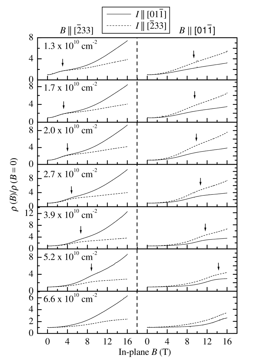
In order to make the data easier to track, we scale the traces to the , base- value of . Figure 6 shows such data for various densities, organized by the relative orientations of and the crystal axes. All traces have an overall positive MR and, in addition, show a broad feature: there is an inflection point followed by a reduction in slope, followed by another inflection point beyond which the traces curve upwards again. To highlight this behavior, the arrows in Fig. 6 are placed between the two inflection points, at a we will refer to as . Surprisingly, for each density, for the traces is about 4 T smaller than for the traces, regardless of the direction. Also, becomes smaller as the density is reduced. Figure 6 reveals that the relative orientations of and the crystal axes play an important role in the MR features.
The existence of the MR features around is intriguing. Similar, though sharper, features have been observed in in-plane measurements in systems with multiple confinement subbands when a subband is depopulated [35]. Similarly, the features in our data may be related to a spin-subband depopulation and the resulting changes in subband mobility and inter-subband scattering as the in-plane is increased. In support of this hypothesis, numerical calculations similar to the ones described above show that the spin-subband depopulation happens at much lower for than for [34]. This reflects the highly anisotropic spin-subband structure of the 2D hole systems in GaAs (311)A QWs. Our hypothesis is further supported by the observation (Fig. 6) that while clearly depends on the orientation of with respect to the crystal axes, it is rather insensitive to the current direction: spin-subband depopulation should not depend on the direction of current in the sample.
At higher in-plane , beyond the MR features around , the data in Fig. 6 are qualitatively similar. The traces for have greater slope than the corresponding traces with , regardless of crystal axes. In this regime the magnetic confinement can become comparable to the electric confinement, and the effects due to the finite-thickness of the 2DHS may be dominant. Indeed, Ref. [22] predicts that MR with in-plane should be significantly larger for than for , in agreement with our highest data.
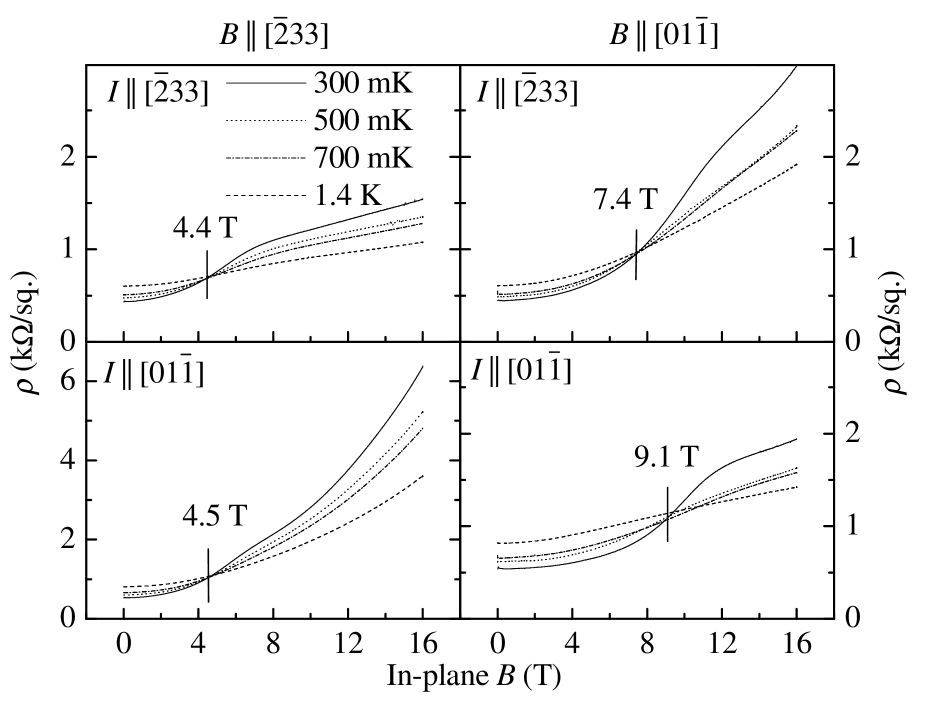
Figure 7 shows the -dependence of the MR at a density of cm-2, for the four measured relative orientations of , , and the crystal axes. For each panel, the traces exhibit a nearly -independent magnetic field which occurs near the trace’s first inflection point. This is consistent with the data of Ref. [18]. For , the data show metallic behavior, and for , insulating behavior. is different in each panel and, similar to , depends much more strongly on the orientation of the crystal axes relative to than on the orientation of relative to . Our experiments indicate that and depend very similarly on the parameters of our systems (, , direction of ). Our observation, which is in agreement with the in-plane MR data of Ref. [16], strongly suggests that the metallic behavior is linked to the presence of two populated spin-subbands [12, 13, 19, 20].
VI Summary
We have demonstrated tunable spin-splitting at constant density in a GaAs 2D hole system. In the process, we have discovered that systems with a significant spin-orbit interaction show a more complicated relationship between the spin-subband populations and the frequencies present in the Shubnikov-de Haas oscillations than had previously been expected. Using the tunability of the spin-splitting to investigate its effect on the metallic behavior observed in this 2D system, we find that changing the magnitude of the spin-subband population difference changes the -dependence of .
Through the use of an in-plane magnetic field, we have measured a surprising anisotropy of the subband structure of (311)A GaAs 2D holes. When a magnetic field is applied in the plane of the 2D system parallel to the direction, the upper spin-subband is depopulated at a significantly lower field than if the field is applied parallel to the direction. Furthermore, we observe that the metallic behavior turns into insulating near at which the upper spin-subband depopulates.
Finally, we note that Das Sarma and Hwang have recently reported calculations aiming to explain the -dependence of the resistivity [33] and the in-plane MR [22] of 2D systems that exhibit metallic behavior at finite . Their calculations, which include only charged impurity scattering and the orbital motion, qualitatively reproduce some of the experimental data. We wish to point out that our results reveal the importance of the spin degree of freedom, and suggest that for an understanding of the experimental data it is important to also consider a scattering mechanism involving the spin-subbands, perhaps intersubband scattering [19, 20]. Also important for (311)A GaAs 2D holes is the inclusion of interface roughness scattering: both the -dependence of at (Fig. 2b), as well as the in-plane MR data (Fig. 6), depend on the direction of the current in the crystal.
This work was supported by the ARO and the NSF.
REFERENCES
- [1] J. P. Eisenstein, H. L. Störmer, V. Narayanamurti, A. C. Gossard, W. Wiegmann, Phys. Rev. Lett.53, 2579 (1984); B. Das et al., Phys. Rev. B39, 1411 (1989); P. D. Dresselhaus, C. M. A. Papavassiliou, R. G. Wheeler, and R. N. Sacks, Phys. Rev. Lett.68, 106 (1992); M. Schultz et al., Semicon. Sci. Technol. 11, 1168 (1996); B. Jusserand et al., Phys. Rev. B51, 4707 (1995); J. Nitta, T. Akazaki, H. Takayanaga, and T. Enoki, Phys. Rev. Lett.78, 1335 (1997); K. Muraki and Y. Hirayama, Physica B 249, 65 (1998).
- [2] J. P. Lu, J. B. Yau, S. P. Shukla, M. Shayegan, L. Wissinger, U. Rossler, and R. Winkler, Phys. Rev. Lett.81, 1282 (1998).
- [3] Y. A. Bychkov and E. I. Rashba, Pisma Zh. Eksp. Teor. Fiz. 39, 66 (1984) [JETP Lett. 39, 78 (1984)]. For a review, see U. Rössler, F. Malcher, and G. Lommer, in High Magnetic Fields in Semiconductor Physics II, edited by G. Landwehr (Springer, Berlin, 1989) [Springer Series in Solid State Sciences, 87] p. 376.
- [4] R. Winkler, S. J. Papadakis, E. P. D. Poortere, and M. Shayegan, Phys. Rev. Lett.84, 713 (2000).
- [5] S. V. Kravchenko, G. V. Kravchenko, and J. E. Furneaux, Phys. Rev. B 50, 8039 (1994); S. V. Kravchenko et al., Phys. Rev. B 51, 7038 (1995); S. V. Kravchenko, D. Simonian, M. P. Sarachik, W. Mason, and J. E. Furneaux, Phys. Rev. Lett. 77, 4938 (1996).
- [6] D. Popović, A. B. Fowler, and S. Washburn, Phys. Rev. Lett.79, 1543 (1997).
- [7] P. T. Coleridge, R. L. Williams, Y. Feng, and P. Zawadzki, Phys. Rev. B56, R12764 (1997).
- [8] J. Lam, M. D’Iorio, D. Brown, and H. Lafontaine, Phys. Rev. B56, R12741 (1997).
- [9] Y. Hanein, U. Meirav, D. Shahar, C. C. Li, D. C. Tsui, and H. Shtrikman, Phys. Rev. Lett.80, 1288 (1998).
- [10] M. Y. Simmons, A. R. Hamilton, T. G. Griffiths, A. K. Savchenko, M. Pepper, and D. A. Ritchie, Phys. Rev. Lett.80, 1292 (1998).
- [11] S. J. Papadakis and M. Shayegan, Phys. Rev. B57, R15068 (1998).
- [12] S. J. Papadakis, E. P. De Poortere, H. C. Manoharan, M. Shayegan, and R. Winkler, Science 283, 2056 (1999).
- [13] S. J. Papadakis, E. P. De Poortere, H. C. Manoharan, M. Shayegan, and R. Winkler, Physica E 6, 284 (2000).
- [14] V. M. Pudalov, G. Brunthaler, A. Prinz, and G. Bauer, Pis’ma Zh. Éksp. Teor. Fiz. 65, 168 (1997), [JETP Lett. 65, 932 (1997)].
- [15] D. Simonian, S. V. Kravchenko, M. P. Sarachik, and V. M. Pudalov, Phys. Rev. Lett.79, 2304 (1997).
- [16] T. Okamoto, K. Hosoya, S. Kawaji, and A. Yagi, Phys. Rev. Lett.82, 3875 (1999).
- [17] K. M. Mertes, D. Simonian, M. P. Sarachik, S. V. Kravchenko, and T. M. Klapwijk, Phys. Rev. B60, R5093 (1999).
- [18] J. Yoon, C. C. Li, D. Shahar, D. C. Tsui, and M. Shayegan, cond-mat/9907128 .
- [19] S. S. Murzin, S. I. Dorozhkin, G. Landwehr, and A. C. Gossard, JETP Lett. 67, 113 (1998).
- [20] Y. Yaish, O. Prus, E. Buchstab, S. Shapira, G. Ben Yoseph, U. Sivan, and A. Stern, cond-mat/9904324.
- [21] G. H. Chen, M. E. Raikh, and Y. S. Wu, cond-mat/9904451.
- [22] S. Das Sarma and E. H. Hwang, cond-mat/9909452.
- [23] J. J. Heremans, M. B. Santos, K. Hirakawa, and M. Shayegan, J. Appl. Phys. 76, 1980 (1994).
- [24] M. Wassermeier, J. Sudijono, M. D. Johnson, K. T. Leung, B. G. Orr, L. Däweritz, and K. Ploog, Phys. Rev. B51, 14721 (1995).
- [25] The asymmetry of the and the spin-subband densities visible in Fig. 4 for compared with is due to the low-symmetry growth direction [311] of our sample. See Ref. [4] for details.
- [26] The resolution of the FFTs, especially the calculated ones, is good enough that they should have displayed two peaks if two frequencies, corresponding to the spin-subband densities predicted by Eq. 1, were present.
- [27] L. Onsager, Phil. Mag. 43, 1006 (1952).
- [28] E. Abrahams, P. W. Anderson, D. C. Licciardello, and T. V. Ramakrishnan, Phys. Rev. Lett.42, 673 (1979).
- [29] D. J. Bishop, D. C. Tsui, and R. C. Dynes, Phys. Rev. Lett.44, 5737 (1980).
- [30] V. M. Pudalov, Pis’ma Zh. Éksp. Teor. Fiz. 66, 168 (1997) [JETP Lett. 66, 175 (1997)].
- [31] V. Dobrosavljević, E. Abrahams, E. Miranda, and S. Chakravarty, Phys. Rev. Lett.79, 455 (1997).
- [32] B. L. Altshuler and D. Maslov, Phys. Rev. Lett.82, 145 (1999).
- [33] S. Das Sarma and E. H. Hwang, Phys. Rev. Lett.83, 164 (1999).
- [34] S. J. Papadakis, E. P. De Poortere, M. Shayegan, and R. Winkler, cond-mat/9911239.
- [35] J. Jo, A. Garcia, K. M. Abkemeier, M. B. Santos, and M. Shayegan, Phys. Rev. B47, 4056 (1993).