Electron Transport in Hybrid Ferromagnetic/Superconducting Nanostructures
Abstract
We observe large amplitude changes in the resistance of ferromagnetic () wires at the onset of superconductivity of adjacent superconductors (). New sharp peaks of large amplitude are found in the magnetoresistance of the -wires. We discuss a new mechanism for the long-range superconducting proximity effect in nanostructures based on the analysis of the topologies of actual Fermi-surfaces in ferromagnetic metals.
keywords:
superconductivity, proximity effect, advanced magnetismPACS:
74.50.+r , 74.80.Fp , 85.30.St1 Introduction
Among the highlights of recent investigations in the field of mesoscopic superconductivity is the discovery of the proximity effects in disordered ferromagnetic (F) conductors [1, 2, 3, 4, 5, 6]. Several theoretical works have been published recently [7, 8, 9], giving an account for some of the features of the observed effects, however the origin of the large decrease in the resistance of ferromagnetic wires [4] and long range effects [1] are yet to be explained. In this paper we report new results on the dependence of the proximity effects in diffusive mesoscopic structures on applied magnetic. To separate the contribution of the bulk and interface effects we measure simultaneously the barrier resistance of the interfaces and the resistance of the -wires. The amplitude and character of the observed effects cannot be explained on the base of the interface phenomena, suggested recently in [10]. We discuss a new mechanism for the long-range superconducting proximity effect in ferromagnetic/superconducting nanostructures based on the analysis of the topologies of actual Fermi-surfaces in ferromagnetic metals.
2 Experimental
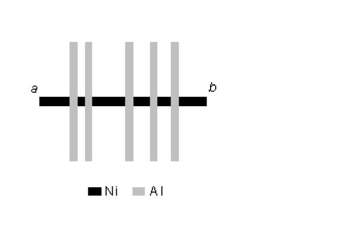
The geometry of the structures is shown in Fig. 1. The structures were made by multi-layer e-beam lithography. The first layer was Ni wire in contact with Al wires of the second layer. We measured the resistance of Ni wires using pairs of Al wires as potential leads with current flowing through Ni wire from point to , in the temperature range from 0.28K to 6K in magnetic fields up to 5T applied perpendicular to the substrate. The value of r for the Ni and Al films was about 12 cm and 0.8 cm, and diffusion constants, , of about 40 cm2/s and 200 cm2/s, correspondingly.
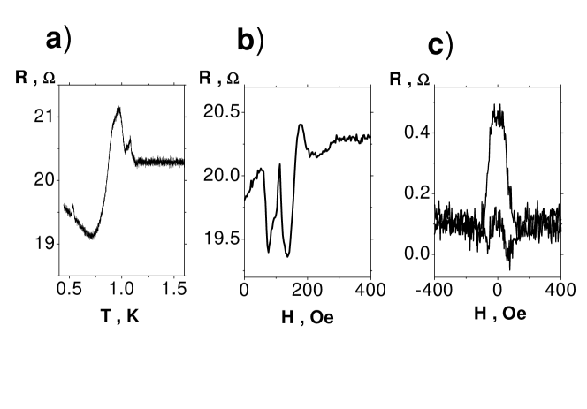
The dependence of the resistance of one of our Ni wires on temperature is shown in Fig. 2a. The sheet resistance of Ni and Al wire was 5 and 0.15 , respectively. The width, and thickness, of Ni wire were 250 nm and 22 nm. The width and thickness of Al potential leads were 100 nm and 55 nm with distance, , of 1000 nm between them. It is seen from Fig. 2a that the value of the resistance of the Ni wire in the minimum is lower than that in normal state by 1.2 . The total peak-to-peak amplitude of the effect is more than 2 . The changes in the resistance are much larger that the Ni/Al barrier resistance in both the normal and superconducting state (see Fig. 2c). The sign of the effect for the wire is opposite to that for both barriers involved: the resistance of the barrier in superconducting state is higher than that in normal, while the resistance of the wire is lower. An example of the dependence of the zero bias resistance for the same sample on magnetic field is shown in Fig. 2b. One of the striking features of the dependence is the sharp peak at 110 G.
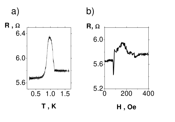
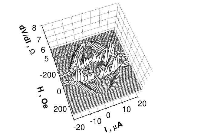
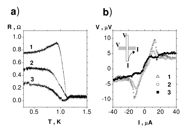
Figures 3a and 3b show the dependence of the resistance on magnetic field and temperature of the segment of Ni wire 250 nm wide 40 nm thick with distance between the potential leads of 400 nm long. The sheet resistance of Ni and Al were 3.4 and 0.15 , respectively. A sharp dip is seen at the magnetic field of 70 G. The dependence of the resistance on temperature (Fig. 3a) shows maximum followed by a plateau. The low-temperature value of the resistance is lower than that in the normal state. We observe sharp features in the differential resistance vs current, , at the magnetic field of 70 G (Fig. 4). Figs. 5a and 5b show the temperature dependence of the resistance of the barriers, , between Ni and Al wires and their voltage-current characteristics. For this sample the value of increases from 0.05 by more that order in magnitude when Al wire goes superconducting. Note, that the temperature dependence of the barrier resistance may strongly deviate from the dependence of the model contacts suggested in [10], described by an admixture of a tunnel and ballistic contact. While the temperature dependencies of the contacts shown in Fig. 5 follow qualitatively the ”mixed” model at temperatures close to , at lowest temperatures an unexpected drop in the resistance may take place (see upper curve).
It is seen from Figures 2 and 3 that the behaviour of the resistance of -wires below the critical temperature is strongly sample-dependent. We find that the amplitude of the changes and even their sign may differ from sample to sample, however, the main features, including the absence of correlation between the resistance of the barriers and that of the wires are common for all ten samples we have measured. A comparison of the dependence on temperature and magnetic field of the resistance of barriers (Fig. 2c and 5) and that of the ferromagnetic wires (Fig. 2a, b and 3) shows that the effect in wires cannot be accounted for by the changes in the barrier resistance alone as suggested in [10].
3 Discussion
The observed effects can be explained by the changes in the bulk resistance of the ferromagnetic wires. An additional confirmation of that comes from the measurements with Ni wires of different thickness at the same thickness of Al wires. We find that the peak-to-peak resistance change on average increases with the decrease in the Ni wire thickness.
The theories developed so far are based on several fundamental differences between the and systems. Only a fraction of electrons can be Andreev reflected at an interface making it an effective spin filter. Furthermore, in a ferromagnet with the exchange field energy, , the Andreev reflected quasi-particles acquire a momentum of where is the Fermi velocity [11]. The latter results in an exponential decay of the superconductor-induced wave functions in diffusive conductors over microscopic distances, , where is the Curie temperature, is the diffusion constant. Hence the amplitude of long-range effects in diffusive systems with small superconducting gap, , is predicted to be negligibly small.
The above arguments are based on idealised isotropic models of the Fermi-surfaces of ferromagnetic metals. However, in real metals the exchange interaction is anisotropic with the value of strongly depending on the position of the Andreev reflected electrons on the Fermi-surface. We emphasise that the value of may vanish for certain electron pairs with opposite spins and directions of momentum [12]. Moreover, there may exist mixed-spin ”pockets” of the Fermi surface [13]. We argue that such groups of electrons may be Andreev-reflected with no effects of the exchange interaction and hence originate the long-range proximity effects in hybrid nanostructures.
The amplitude of the superconducting condensate functions on the -side should depend on the life times of the electrons in the mixed-spin groups, that in principle can be larger than the averaged over the Fermi surface transport relaxation time (see e.g. [14] and references therein).
The mechanism suggested above together with the processes at the interfaces [8, 9, 10] and the dependence of the number of mixed spin electrons on magnetic field [15] may account for the sample specific variations of the effects in our polycrystalline wires.
We acknowledge financial support from the EPSRC (Grant Ref: GR/L94611).
References
- [1] V.T. Petrashov, V.N. Antonov, S.V. Maksimov, and R.Sh. Shaikhaidarov, JETP Lett. 59, 551 (1994).
- [2] M.D. Lawrence and N. Giordano, J. Phys. Cond. Matt. 8, L563 (1996).
- [3] M. Giroud, H. Courtois, K. Hasselbach, D. Mailly, and B. Pannetier, Phys. Rev. B 58, 11872 (1998).
- [4] V.T. Petrashov, I.A. Sosnin, I. Cox, A. Parsons, and C. Troadec, Phys. Rev. Lett. 83, 3281 (1999).
- [5] M. Giroud, K. Hasselbach, H. Courtois, D. Mailly, and B. Pannetier, in Mesoscopic Superconductors and Hybrid Structures, COST-TMR-CCP9 Workshop, 16-19 December 1999, Lancaster, UK.
- [6] M.D. Lawrence and N. Giordano, J. Phys. Cond. Matt. 11, 1089 (1999).
- [7] M.J.M. de Jong and C.W.J. Beenakker, Phys. Rev. Lett. 74, 1657 (1995).
- [8] F.J. Jedema, B.J. van Wees, B.H. Hoving, A.T. Filip, T.M. Klapwijk, Phys. Rev. B 60, 16549 (1999).
- [9] V.I. Fal’ko, C.J. Lambert, A.F. Volkov, JETP Lett. 69, 532 (1999).
- [10] W. Belzig, A. Brataas, Yu.V. Nazarov, G.E.W. Bauer, cond-mat/0005188.
- [11] E.A. Demler, G.B. Arnold, and M.R. Beasley, Phys. Rev. B 55, 15174 (1997).
- [12] C.S. Wang and J. Callaway, Phys. Rev. B 15, 298 (1977).
- [13] G. Lonzarich in Electrons at the Fermi surface, ed. M. Springford, Cambridge University Press, 1980.
- [14] Int. Conf. on Electron life times in metals, J. Phys. Cond. Matt. 19, 3 (1975); A.K. Geim, V.T. Petrashov, and M. Zolotarev, Sov. Phys. JETP 91, 2101 (1986).
- [15] R. Gersdorf, Phys. Rev. Lett. 40, 344 (1978).