Small polaron formation in dangling-bond wires on the Si(001) surface
Abstract
From electronic structure calculations, we find that carriers injected into dangling-bond atomic wires on the Si(001) surface will self-trap to form localised polaron states. The self-trapping distortion takes the form of a local suppression of the buckling of the dimers in the wire, and is qualitatively different for the electron and hole polarons. This result points to the importance of polaronic effects in understanding electronic motion in such nanostructures.
pacs:
68.65.+g; 73.20.Dx; 71.15.Nc; 71.38.+iDevelopments in nanotechnology are placing increasing demands on our understanding of electron transport in confined systems; this applies particularly to coherent quantum transport and tunnelling phenomena. Among the most promising one-dimensional structures that have been produced by nanolithography are ‘dangling-bond wires’, formed by the selective removal of H atoms from the H-saturated Si(001) surface with a scanning tunnelling microscope[3, 4]. In this letter we show that carriers injected into these dangling-bond wires self-localise to form polarons; this process is crucial in determining the transport properties of the wires.
There is good experimental evidence that a Peierls distortion occurs at low teperatures in a dangling-bond wire[6], although there is still debate about the extent of the underlying structural distortion[4, 6]; this distortion removes the one-dimensional metallic density of states and produces a narrow-gap one-dimensional semiconductor[5]. In systems with Peierls distortions, charge transport is dominated by polaron species [7, 8]; this is true both when charge is permanently introduced into the wire by doping, and also when the charge enters the chain only transiently, as part of a quantum mechanical tunnelling event [9]. However, recent calculations of the transport properties of dangling-bond wires do not include polaronic effects [10]. It is therefore of great importance to determine whether such polarons are, in fact, formed in this system, where the electrons in the wire are strongly coupled to a three-dimensional substrate and so a purely one-dimensional picture is not applicable.
In this letter we provide clear theoretical evidence that polarons will form when holes (or, as discussed later, electrons) are injected into a dangling-bond wire. We calculate the binding energy, atomic distortion, and wavefunction localisation of the polarons, and provide realistic estimates of the effective mass and of the effect that polaron formation will have on the coherent transport of charge along the wire.
We use three different methods to perform our calculations. The first is density functional theory in the local density approximation (LDA), with a plane-wave basis set and norm-conserving pseudopotentials[11, 12, 13]. We use a plane-wave energy cutoff of 200 eV. However, the formation of polarons is expected to involve long-range atomic distortions extending over many surface unit cells; to capture these effects, an accurate but approximate method is required which includes the interplay between electronic and atomic structure. We therefore use two variants of a total-energy orthogonal tight-binding method[14, 15], implemented in the OXON package. In one form the wavefunctions are calculated by explicit diagonalisation of the tight-binding Hamiltonian (we shall refer to this as tight binding, since the computational effort scales as the cube of the system size). In the other form, the one-electron density matrix is calculated directly, while truncating it at a finite number of nearest-neighbour ‘hops’, to produce a scheme which scales linearly with system size ( tight binding) [16, 17]. The same tight-binding parameters are used in both cases; the silicon-silicon parameters[18, 19] have been shown to provide a good account of the elastic properties and band structure of bulk Si, while the silicon-hydrogen parameters [19] give a good account of the structure and diffusion of H on Si(001)[20, 21, 22]. The method is extremely efficient for searching configuration space in large unit cells; all the structures and energies were subsequently validated with the technique, and it is these numbers that are reported here.
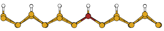
We performed calculations on several different unit cells, always using a slab geometry with periodic boundary conditions. The number of Si layers perpendicular to the surface is 5 for the LDA calculations (with the final layer terminated in H and constrained to lie in bulk-like positions), 10 for the tight-binding calculations (with the final layer terminated in H, and the bottom five layers constrained to lie in bulk-like positions), and 6 for the tight-binding (again H-terminated, with the bottom layer frozen). The lengths of the different cells along the wire axis were 2 and 12 dimers, and the cells were two dimer rows wide in all cases. A single dangling-bond wire was introduced into the calculations by removing one line of H atoms along a dimer row direction. The topmost section of the cell is shown in Figure 1, with the trapping distortions of the hole and electron polarons.
We begin by describing our calculations of the wire in its uncharged state. We used the 2-dimer cell, and performed the calculations using both the LDA and tight-binding (using a Monkhorst-Pack -point mesh in both cases, making use of time-reversal symmetry); this gave us a check on the accuracy of the tight-binding scheme with which we subsequently treated the polaron species. In agreement with previous work, we found that the Peierls distortion manifested itself as an alternating up and down displacement of the clean Si atoms forming the dangling bond wire. Table I shows the key structural parameters obtained in LDA and by tight-binding in the 2-dimer cell; the only significant difference is in the Si-H bond lengths, which are not important for the distortions we discuss in this paper. The height difference between the ‘up’ and ‘down’ Si atoms in the wire is well reproduced. The relaxation energies found from both LDA and tight-binding calculations agree well.
The electron density is higher on the up atom (reflecting the move towards sp3 hybridisation) and lower on the down atom (which is more sp2-like, with an empty p orbital). This is somewhat analogous to the tilted dimer structure seen on the clean Si(001) surface. The band structures for the highest occupied states from the LDA and from the tight-binding are compared in Figure 2. We see that the two are very similar; in particular, the dispersion of the highest occupied band is very similar in the two cases. This is important, because the electronic states associated with the polaron are predominantly derived from this bands. In the course of this comparison, we found that the structural and electronic properties of the system are very sensitive to the surface -point sampling used to construct the LDA charge density. Relaxation at a single special -point in the surface Brillouin zone gave a non-zero Peierls distortion, but produced an electronic structure with qualitatively different dispersion; however, a Monkhorst-Pack mesh was found to be sufficient. This is not surprising for a system exhibiting a Peierls distortion, where the charge density is expected to be sensitive to the -point sampling in the vicinity of the Fermi points.
We investigated the formation of a hole polaron using tight binding by removing a single electron from the 12-dimer cell. This cell contains 612 atoms (for the method) or 420 atoms ( method); bulk-like atoms were removed from the bottom of the slab for the calculations for reasons of computational efficiency, with negligible effect on the results. Only the -point of the reduced Brillouin zone was sampled. A single ‘up’ atom of the wire was displaced downwards normal to the surface to break the translational symmetry, and the geometry was then relaxed. It did not revert to the original translationally-ordered state; instead, a localised pattern of distortions occurred in the Si atoms of the wire, predominantly in the direction normal to the surface (Figure 3). (We also found that the symmetry of the translationally-ordered state spontaneously broke to form the same structure.) This distortion was associated with a localisation of the charge. The relaxation energy of the charged system from its translationally ordered state into the polaron state was 0.21 eV. The highest occupied state is found to be localised in the region of the distortion.
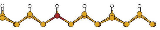
We also calculated the relaxation that follows the addition of an electron to the wire. Once again, a polaron is formed; the major effect now is that one of the ‘down’ wire atoms moves up, accompanied by some distortion of the neighbouring atoms (Figure 4). Once again, a localised distribution of the excess charge and a localised one-electron state are produced. The binding energy of the electron polaron in the 12-dimer cell is 0.16 eV. This is entirely reasonable and consistent with what is predicted for the hole; however, since our tight-binding has been fitted to structural (rather than excited-state) properties and so may not reproduce empty states as well as filled states, we concentrate on the results for the hole polaron in the remainder of the paper.
It is straightforward to understand qualitatively the driving forces behind these displacements. When an electron is removed, there is a tendency to drive the last (now half-occupied) filled state upwards in energy; this can be accomplished by driving one of the sp3-like ‘up’ atoms downwards and making it more sp2-like. Conversely, when an electron is added, there is an advantage in lowering the energy of a formerly empty state; this can be achieved by moving an sp2-like ‘down’ atom upwards to make it more sp3-like. Both motions correspond to a local reduction of the Peierls distortion in a manner appropriate to the sign of the added charge.
It is interesting to compare these polarons with those formed in conducting polymers[7]. In polymers, the dominant distortion is in the bond lengths, and the charge-conjugation symmetry in the system (which holds exactly in the simple Su-Schrieffer-Heeger model[23] and approximately in the real molecules) implies that the electron and hole polarons are similar. In the dangling-bond wire, on the other hand, the dominant distortions are perpendicular to the surface, and the electron and hole polarons are qualitatively different. In both cases, however, one can think of the polaron distortion as producing a local suppression of the band gap; in the conducting polymer this arises from a local reduction of the bond-length alternation, whereas in the dangling-bond wire it arises from the vertical displacement of Si atoms. A further difference is that the distortion in the dangling-bond is more localized; while this makes it particularly easy to justify it post hoc, its form could not have been predicted before our calculations.
In order to quantify the coupling of the carriers to the lattice, and to estimate the dynamical properties of the polarons, we have analysed the polaron distortion in terms of the phonon spectrum of the neutral wire. First we check to see whether the harmonic approximation correctly reproduces the energy change when a neutral system is distorted to the geometry of the hole polaron; we find the harmonic approximation gives , in fair agreement with the full tight-binding result of . (The dominant source of the anharmonicity is in the softening of the flattening Si dimers as the polaron is formed. We have checked that the harmonic approximation becomes exact as the magnitude of the distortion is reduced.) Now for each mode we can calculate a Huang-Rhys factor , where is the relaxation energy of mode in the process of forming the polaron and is the frequency[24]. We find that , putting the system in the weak-coupling regime; we also find that the maximum value of an individual is 0.0056, showing that there is no single mode dominating the distortion. As might be expected, the modes with the largest are those corresponding to motions of the depassivated Si atoms normal to the surface.
We can also find the Huang-Rhys factors corresponding to the displacement of the polaron by two dimers along the wire. We take two adjacent positions for the polaron and calculate a new set of from the differences in the phonon displacements. We find now that —this is very close to , which can be understood because the displacements from the uncharged state corresponding to the two different polaron positions are almost orthogonal in configuration space. Using this result, and the bare electronic bandstructure of the wire, we can estimate the low-temperature effective mass of the polaronic species: the effective hopping integral for the carrier between neighbouring sites is reduced by approximately [25], leading to an enhancement in the effective mass from the bare hole band mass (computed from the tight-binding bandstructure) to for low-temperature coherent transport. Simulations of the classical diffusion of the polarons at high temperatures will be presented in a future publication.
This enables us to assess the likely effect of the polaron formation on electron transport in the wire. If the chemical potential is close to the Fermi level of the substrate, transport through the wire will be by coherent tunnelling. In this regime, strong enhancement of the tunnelling at low temperatures is to be expected, as found in [9]. There will be a crossover to thermal excitation of polarons as the temperature rises. If, on the other hand, the wire is subject to such a strong departure from equilibrium that real (as opposed to virtual) carriers can be injected into it, their effective mass will be enhanced at low temperatures. For both tunnelling and band transport, we can estimate the crossover temperature to thermally-activated hopping motion as being of the order of half the frequency of the most strongly coupled modes [26]; hence, we find for the hole, and about 30% higher for the electron. We therefore expect that room-temperature experiments will be in the high-temperature regime, but that the low-temperature limit should also be experimentally accessible.
Acknowledgements.
We thank the UK Engineering and Physical Sciences Research Council for the award of an Advanced Fellowship (AJF) and a Postdoctoral Fellowship in Theoretical Physics (DRB), and for support under grants GR/M09193 and GR/M01753. We are grateful to Dr H. Ness and Professor A.M. Stoneham for a number of discussions.REFERENCES
- [1] Email david.bowler@ucl.ac.uk.
- [2] Email andrew.fisher@ucl.ac.uk.
- [3] T.-C. Shen et al. Science 253 1590 (1995).
- [4] S. Watanabe, Y.A. Ono, T. Hashizume and Y. Wada, Phys. Rev. B 54 R17308 (1996); Surf. Sci. 386 340 (1997).
- [5] R.E. Peierls Quantum Theory of Solids (Clarendon Press, Oxford 1955) p110.
- [6] T. Hitosugi et al., Phys. Rev. Lett. 82 4034 (1999).
- [7] A.J. Heeger, S. Kivelson, J.R. Schrieffer and W.-P. Su, Rev. Mod. Phys. 60 781 (1988).
- [8] A.J. Fisher, W. Hayes and D.S. Wallace, J. Phys.: Cond. Matt. 1 5567 (1989).
- [9] H. Ness and A.J. Fisher, Phys. Rev. Lett. 83 452 (1999).
- [10] P. Doumergue et al., Phys. Rev. B 59 15910 (1999).
- [11] G. Kerker, J. Phys. C 13 189 (1980).
- [12] L. Kleinman and D.M. Bylander, Phys. Rev. Lett. 48 1425 (1982).
- [13] CASTEP 4.2 Academic Version licensed under the UKCP-MSI agreement (1999); M.C. Payne et al., Rev. Mod. Phys. 64 1045 (1992).
- [14] A.P. Sutton, M.W. Finnis, D.G. Pettifor and Y. Ohta, J. Phys. C 21 35 (1988).
- [15] C.M. Goringe, D.R. Bowler and E.H. Hernández, Rep. Prog. Phys. 60 1447 (1997).
- [16] X.P. Li, W. Nunes and D, Vanderbilt, Phys. Rev. B 47 10891 (1993).
- [17] C.M. Goringe, DPhil Thesis, University of Oxford (1995).
- [18] D.J. Chadi, J. Vac. Sci. Tech. 16 1290 (1979).
- [19] D.R. Bowler et al., J. Phys.: Condens. Matter 10 3719 (1998).
- [20] J.H.G. Owen et al., Phys. Rev. B 54 14153 (1996).
- [21] D.R. Bowler, J.H.G. Owen, K. Miki and G.A.D. Briggs, Phys. Rev. B 57 8790 (1998).
- [22] D.R. Bowler et al., J. Phys.: Condens. Matter (in press).
- [23] W.-P. Su, J.R. Schrieffer and A.J. Heeger, Phys. Rev. Lett. 42 1698 (1979).
- [24] A.M. Stoneham, The Theory of Defects in Solids, Oxford (1975).
- [25] T. Holstein, Ann. Phys. 8 325 and 343 (1959).
- [26] I.G. Lang and Y.A. Firsov, Sov. Phys. JETP 16 1301 (1963).
 |
| (a) |
 |
| (b) |
 |
| (a) |
 |
| (b) |


| Bond length (Å) | LDA | Tight binding |
| Si-Si in ‘up’ wire dimer | 2.42 | 2.43 |
| Si-Si in ‘down’ wire dimer | 2.38 | 2.36 |
| Si-Si in non-wire dimer | 2.40 | 2.37 |
| Si-H on ‘up’ wire dimer | 1.55 | 1.50 |
| Si-H on ‘down’ wire dimer | 1.54 | 1.49 |
| between ‘up’ and ‘down’ wire atoms (Å) | 0.67 | 0.57 |
| Peierls energy (eV, per dimer pair) | 0.21 | 0.23 |