Phononic crystals with planar defects
Abstract
We study the effect of planar defects in phononic crystals of spherical scatterers. It is shown that a plane of impurity spheres introduces modes of vibration of the elastic field localized on this plane at frequencies within a frequency gap of a pure phononic crystal; these show up as sharp resonances in the transmittance of elastic waves incident on a slab of the crystal. A periodic arrangement of impurity planes along a given direction creates narrow impurity bands with a width which depends on the position of these bands within the frequency gap of the pure crystal and on the separation between the impurity planes. We show how a slight deviation from periodicity (one impurity plane is different from the rest) reduces dramatically the transmittance of elastic waves incident on a slab of the crystal.
pacs:
43.20.+g, 43.40.+s, 46.40.Cd, 63.30.+dI Introduction
Phononic crystals are composite materials whose elastic properties, as described by the mass density and the Lamé coefficients and , vary periodically in space. In recent years there has been a growing interest in the study of phononic crystals, especially in relation to the possibility of phononic band gap materials (see, e.g., Ref. [2] and references therein). By definition these exhibit regions of frequency (phononic gaps) over which no vibrations are possible within the infinite crystal. This implies that an elastic wave, whatever its direction of propagation and its polarization (longitudinal or transverse), incident on a slab of the material of some thickness will be totally reflected by it, if its frequency lies within a phononic gap. Obvious technological applications of the above are non-absorbing mirrors and vibration-free cavities which might be very useful in high-precision mechanical systems operating in a given frequency range.
On the theory side one would like to be able to calculate the frequency band structure of a phononic crystal and also the transmission and reflection coefficients of elastic waves incident on a slab of the material of finite thickness. In a previous publication [2] (to be referred to as paper I) we presented a formalism which can do that for phononic crystals consisting of non-overlapping spheres embedded in an elastic medium of different mass density and Lamé coefficients. In the present paper we apply the formalism of paper I to a specific system consisting of non-overlapping solid spheres embedded in a solid host medium. We assume that the spheres are centered on the sites of an fcc lattice and view the crystal as a sequence of (001) planes along the axis. We calculate the frequency band structure of the infinite crystal, and the transmission coefficient for an elastic wave incident on a slab of the material parallel to the (001) surface consisting of a finite number of planes of spheres. For a thick slab the transmittance vanishes over the exact range of the band gap (of the infinite crystal) as one would expect; but of greater interest is the fact that the transmittance behaves in almost the same manner for a thin slab consisting of just two planes of spheres.
Linear and point defects in phononic crystals have been investigated by Torres et al.. [3] In the present work we study the effect of planar defects, i.e. of impurity planes, on the transmittance of a slab. An impurity plane has the same two-dimensional (2D) periodicity as the rest of the planes of the slab, but the spheres centered on this plane are different. In our example they have a different radius. This leads to gap states: vibrational modes of the elastic field localized on the impurity plane, which show up as transmission resonances at frequencies within the gap of the pure crystal.
Finally we consider a crystal whose unit cell along the direction consists of a number of planes one of which (impurity plane) is different from the other planes of the unit cell. This leads to impurity bands within the frequency gap of the pure crystal, the width of which depends on the position of the impurity band within the gap and on the separation between the impurity planes. We show that a slight deviation from periodicity reduces dramatically the transmission coefficient of an elastic wave incident on a slab of the crystal.
In all calculations of the transmittance of a slab we assume that the material that exists between the spheres of the slab extends to infinity on either side of the slab.
II Properties of the pure crystal
The pure crystal consists of non-overlapping lead spheres centered on the sites of an fcc lattice. The elastic properties of the spheres are characterized by the mass density, , and the longitudinal and transverse velocities of propagation, denoted by and respectively. The latter are given by: and . For lead we have: , , . The space between the spheres is filled with epoxy ( , , ).
We calculate the complex frequency band structure of the infinite crystal (extending from to ) associated with the (001) surface in the manner described in paper I. For any given reduced wavevector , within the surface Brillouin zone (SBZ) of this surface, we calculate the frequency lines as functions of the angular frequency . Our results, obtained with an angular momentum cut-off and 13 2D reciprocal vectors, , are converged within an accuracy . The ordinary frequency band structure which interests us here, corresponds to real sections (regions of frequency over which is real) of these lines. In Fig. 1(a) we show the frequency bands of the elastic field for (along the direction normal to the (001) plane). We present our results in dimensionless units; denotes the lattice constant of the fcc lattice and the propagation velocity of transverse elastic waves in epoxy. The radius of the spheres equals in the present case which corresponds to a fractional volume occupied by the spheres, denoted by , equal to 0.262.
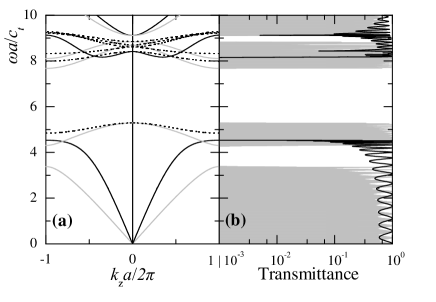
The bands shown in Fig. 1(a) by black (grey) lines correspond to longitudinal (transverse) modes of vibration of the elastic field inside a sufficiently thick slab of the material. These modes are excited only by longitudinal (transverse) waves incident normally on the surface of the slab. This is demonstrated quite clearly in Fig. 1(b), which shows the transmission coefficient of a plane wave incident normally on a slab of the material consisting of 16 planes of spheres parallel to the (001) surface. The shaded curve shows the transmission coefficient for a transverse incident wave and the black line that of a longitudinal incident wave.
We hasten to add (see also paper I) that in a composite material the modes of vibration of the elastic field need not be purely longitudinal or purely transverse even along symmetry directions and, therefore, the fact that they behave so in the system under consideration is worth noting. Off the normal direction () the frequency bands are clearly hybridized and they are excited by either longitudinal or transverse incident plane waves. The bands shown by dotted lines in Fig. 1(a) are deaf bands. The component of the corresponding modes of vibration vanishes and that being the only component which couples with the external elastic field in the frequency range under consideration, they cannot be excited by an incident plane wave, leading to total reflection of the latter. Finally, we point out the oscillations in the transmission coefficient, over the allowed regions of frequency, which are due to interference effects resulting from multiple reflection between the surfaces of the slab (Fabry-Perrot-type oscillations).
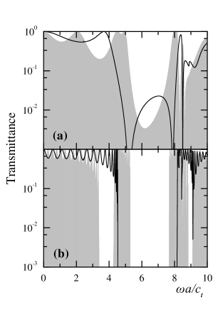
In Fig. 2 we show the transmission coefficient of an elastic wave incident normally on a thin (001) slab consisting of just two planes of spheres, and compare it with the same quantity for a thick slab (of 16 planes of spheres), which as we have seen is determined by the frequency band structure of the infinite crystal. We see that over the frequency region that constitutes the frequency gap of the infinite crystal, the transmittance of a slab consisting of just two planes of spheres is not zero, but it is nevertheless about two orders of magnitude smaller than its value at frequencies below or above the gap edges. The Fabry-Perrot-type oscillations are of course different in the two cases since they depend directly on the thickness of the slab.
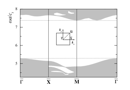
An absolute frequency gap extends between and , as demonstrated in Fig. 3. This shows the projection of the frequency band structure on the SBZ, along the symmetry lines of the latter shown in the inset. The shaded areas correspond to frequencies for which there exists at least one propagating Bloch wave (an eigenmode of the elastic field) in the infinite crystal; in the frequency regions represented by the blank areas none exists. We verified, by calculating the frequency lines at selected points of the SBZ, that the gap does exist over the entire SBZ, and that it is therefore an absolute phononic gap extending from to . The above values of the lower and upper edges of the gap are different from the values and , respectively, found by Kafesaki et al., [4] who studied the same system using the plane-wave method. We believe our results to be the more accurate. It is now recognized that the plane-wave method is not particularly suited to the study of phononic crystals consisting of non-overlapping spheres in a host medium, because of the very large number of plane waves required to obtain convergent results. [5]
III Planar defects
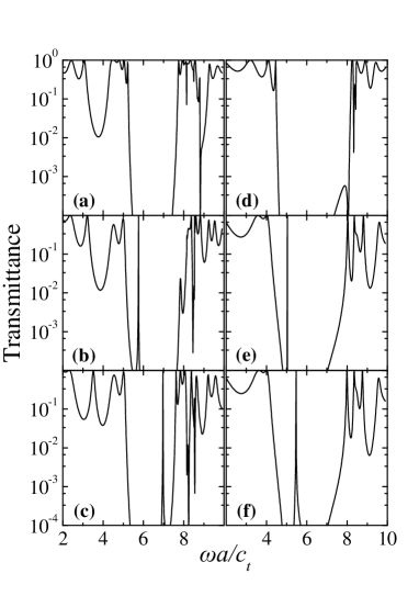
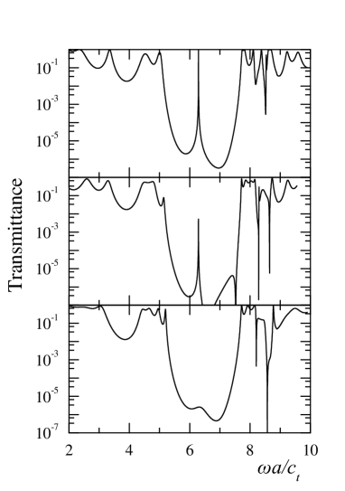
Next we consider a slab of the phononic crystal consisting of five planes of spheres, one of which may be different from the other four. It has the same 2D periodicity parallel to the surface of the slab, but the spheres of this, so-called, impurity plane may be different: they have a smaller or larger radius than the spheres of the other planes. Our results are summarized in the six diagrams of Fig. 4. The first three, (a), (b) and (c), show the transmittance of a transverse elastic wave incident normally on a slab of five planes of spheres. For Fig. 4(a) all five planes are the same, as in the infinite crystal described in the preceding paragraphs, and the transmittance vanishes, as expected, over the frequency region corresponding to the frequency gap of the infinite crystal for , shown in Fig. 1(a). For Figs. 4(b) and 4(c) the middle plane is different from the other four. The spheres of this plane have a smaller radius: for Fig. 4(b) and for Fig. 4(c), where S is the radius of the spheres in the other planes. The transmission resonance that now appears at a frequency within the gap signifies the existence of a state of the elastic field centered on the impurity plane: a mode of vibration of the elastic field that extends to infinity parallel to the surface of the slab (in the manner of a Bloch wave), but decays rapidly normal to the impurity plane on either side of it. It appears that the normal mode of vibration (with ) at the top of the valence band (we use the term by analogy to semiconductor physics to denote the frequency band below the gap), splits off this band, becoming a localized (on the impurity plane) vibration, with a frequency higher in the gap the smaller the radius of the impurity spheres. Figs. 4(d) to 4(f) demonstrate the same phenomenon for longitudinal waves incident normally on the slab. For Fig. 4(d) all five planes are the same as in the infinite crystal, and the transmission coefficient accords with the corresponding frequency band structure shown in Fig. 1(a). For Figs. 4(e) and 4(f) the spheres of the middle plane have a radius smaller than that of the other four planes: for Fig. 4(e) and for Fig. 4(f). We note that while the trend is the same, the resonance frequency stays closer to the top of the valence band for longitudinal waves.
We note that the transmission coefficient equals unity at the resonance frequency. This is the case when the impurity plane lies in the middle of the slab; when the impurity plane is any other than the middle plane, the transmission coefficient at the resonance frequency is less than unity, as demonstrated in Fig. 5. This figure shows the transmission coefficient for a transverse plane wave incident normally on a slab of five planes of spheres one of which is an impurity plane. The spheres centered on this plane have a radius , where is the radius of the spheres of the other planes. The top diagram is obtained when the impurity plane is the middle plane of the slab, the middle diagram is obtained when the impurity plane is the second from the surface, and the third diagram is obtained when the impurity plane lies at the surface of the slab. Only in the first case is the transmission coefficient at resonance equal to unity. When the impurity plane is removed from the center of the slab by one plane, the value of the transmission coefficient at resonance diminishes by at least two orders of magnitude (middle diagram), and the resonance disappears altogether when the impurity plane is removed to the surface of the slab. Similar results are obtained for a longitudinal incident wave. This is indeed a general characteristic of resonant tunneling. We note, for example, the similarity of the above results with those obtained in the transmission of an electron through a double barrier, when the well between the two barrier tops allows for a resonance state of the tunneling electron. When the double barrier is symmetric the transmission coefficient at resonance equals unity, when the double barrier is not symmetric the transmission coefficient is less than unity. [6]
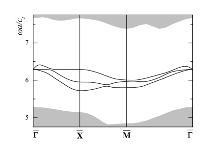
In Fig. 6 we show the variation with of the resonance frequency, associated with an impurity plane at the middle of a slab of five planes of spheres. The spheres of the middle plane have a radius , where is the radius of the spheres in the other planes. The gap states/resonances along and are hybridized, excited by both longitudinal and transverse incident plane waves. The states/resonances along corresponding to the two top bands are excited by -polarized transverse waves ( the displacement vector is parallel to the surface of the slab); the third band is excited by both longitudinal and -polarized waves (the displacement vector lies in the plane of incidence). We note that all three bands of gap states are restricted within a rather narrow range of frequencies about the midgap frequency.
Next we consider an infinite crystal (extending from to ) the unit cell of which, along the axis, consists of three fcc planes of spheres; we have: . The spheres of the third plane of the unit slice have a radius which is smaller than the radius of the spheres of the other two planes. We put . The resonances shown in Fig. 6 now develop into bands shown by shaded regions in Fig. 7. These bands are nevertheless extremely narrow for most , which implies that the vibrations are strongly localized on the impurity planes, with very little interaction between impurity planes. This is, of course, consistent with the sharpness of the resonance seen in a slab of five planes (see top diagram of Fig. 5).
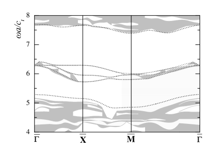
We can vary the width of the impurity bands by pushing them away from the middle of the gap. Putting displaces the impurity bands of Fig. 7 towards the bottom of the gap; at the point this leads to a band-width of which is more than three times that shown in Fig. 7 which equals . We can understand this by noting that the interaction between states localized on neighboring impurity planes depends on the separation, , between the planes approximately as , where is the smallest (in magnitude) of the imaginary parts of the frequency lines in the pure crystal over the frequency range of the impurity band. is largest in the middle of the gap (for a given ) and goes to zero at the edges of this gap.
Finally, in Fig. 8 (curve (A)) we show the transmission coefficient in the frequency region of the impurity band for a transverse wave incident normally on a slab of a phononic crystal consisting of seven unit cells along the direction, when the unit slice consists of three (001) fcc planes: , with the spheres of the third plane having a radius with .
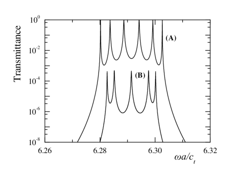
We note that the frequency gap of the pure crystal () for
extends from to
. We recall that the gap states corresponding to
the first six impurity planes (taken individually) manifest
themselves as transmission resonances at
(see Fig. 5) while the seventh impurity plane, at the
surface of the slab, does not give a transmission resonance, as shown
in the bottom diagram of Fig. 5. The interaction between the
impurity planes removes the degeneracy of the above resonance level,
leading to six discrete resonances in the transmission spectrum, as
shown in Fig. 8. Curve (B) of Fig. 8 is obtained
for a slab which differs from the above in that the spheres of the
third plane of the third unit slice have a radius , instead
of . We note the dramatic reduction, by about four orders
of magnitude, in the transmission coefficient as a result of the
presence of just one different impurity plane. In a way this
phenomenon, which may have interesting technological applications, is
to be expected; the different impurity plane decouples the vibrations
on its right from those on its left. This suggests that a random
distribution of impurity planes will lead to vibrational modes
localized over smaller regions of the slab. We have here a
possibility to study Anderson localization of classical waves in an
effectively one-dimensional system (because of
conservation) which allows direct comparison with corresponding
experimental data, without the difficulty associated with correlation
in the corresponding electronic problem.
REFERENCES
- [1] Also at the Department of Physics, National Technical University of Athens, Zografou Campus, GR-157 73, Athens, Greece.
- [2] I. E. Psarobas, N. Stefanou and A. Modinos, Phys. Rev. B62 (2000).
- [3] M. Torres, F. R. Montero de Espinosa, D. García-Pablos, and N. García, Phys. Rev. Lett.82, 3054 (1999).
- [4] M. Kafesaki, M. M. Sigalas and E. N. Economou, Solid State Commun. 96, 285 (1995).
- [5] M. Kafesaki and E. N. Economou, Phys. Rev. B60, 11993 (1999).
- [6] A. Modinos and N. Nicolaou, Surf. Sci. 17, 359 (1969).