Shapes, contact angles, and line tensions of droplets on cylinders
Abstract
Using an interface displacement model we calculate the shapes of nanometer-size liquid droplets on homogeneous cylindrical surfaces. We determine effective contact angles and line tensions, the latter defined as excess free energies per unit length associated with the two contact lines at the ends of the droplet. The dependences of these quantities on the cylinder radius and on the volume of the droplets are analyzed.
pacs:
68.45.Gd,68.10.-m,82.65.DpI Introduction
The wetting properties of a fiber in liquid matrices (e.g., dye mixtures, polymer melts, or molten resins) play an important role in the textile industry and in the fabrication of high-performance, fiber-reinforced composite materials. Since contact angles of liquid droplets on solid substrates provide a valuable characterization of such wetting properties there are numerous experimental and theoretical studies of the shape and the spreading of droplets deposited on a cylindrical substrate (see, e.g., Refs. [1, 2, 3, 4, 5, 6, 7, 8, 9, 10, 11, 12, 13, 14, 15]). The morphology of liquid drops on a fiber is particularly interesting insofar as on a planar substrate there is only one, spherical caplike droplet shape, whereas on a cylindrical substrate droplets may exhibit two, topologically different shapes, a “clamshell”- and a “barrel”-type one, depending on the droplet volume, the contact angle, and the cylinder radius [1, 2, 3]. The aforementioned studies deal with thick fibers and large drops, i.e., the length scales are m and larger. In this range the fluid structures are determined by macroscopic properties alone, i.e., volume of the liquid, surface tension of the liquid vapor interface, Young’s contact angle , and radius of the cylinder.
However, with the discovery of nanotubes the interest in such fluid structures has shifted to much smaller scales. There are several applications for which these small solid-fluid structures are very important. (i) For fabricating valuable composite materials involving nanotubes their wetting by the liquid host matrix is necessary to couple the inherent strength of the nanotubes to the matrix, reinforcing materials or fillers for plastics and ceramics [16]. (ii) Nanotubes can be used as supports for heterogeneous catalysis or as templates for creating small wires or tubular structures by coating them with metals or metal oxides in the liquid state [17] or by attaching inorganic and organic moieties to the nanotube surfaces [18]. (iii) In order to use nanotubes as “nanostraws” potential candidates for exploiting such capillarity must be screened by first seeing if the liquid wets the outside of nanotubes [19]. The performance of the nanotubes as catalysts, adsorbants, and deodorants can vary depending on whether they are composed of carbon, boron nitride, or oxides (SiO2, Al2O3, V2O5, MoO3, TiO2) [20]. This variety demonstrates, that the substrate potential of these tubes can be regarded as a tunable parameter. (iv) By using nanotubes as nanotweezers [21] it might be possible to grab and manipulate small liquid drops. For this application the substrate must be nonwettable.
These small scales are comparable with the range of the substrate potential of the cylinders and of the molecular forces between the fluid particles adsorbing on them. Thus the droplets form under the action of the so-called effective interface potential which accounts for the net effect of the competition between the forces among the fluid particles and the substrate potential [22]. Accordingly the calculation of the corresponding deformed droplet shapes requires a more detailed theoretical description which takes the effective interface potential into account. To our knowledge there is only one, recent publication in which this effect of on the droplet shape on fibers has been analyzed [23]. It is the purpose of our study here to refine and to extend this analysis in various directions. If the radius of the fiber reduces to a few nm, as it is the case for nanotubes, the effective interface potential itself will depend on and thus deviate from that of the corresponding semi-infinite planar substrate used in Ref. [23]. Accordingly we present a systematic analysis of the dependence of the shape of the droplets and their suitably defined contact angles on both and the droplet volume. This enables us to describe systematically the crossover in shape and contact angle between those of droplets on a cylinder and on the limiting case of a planar substrate. We remark on how the structure of the effective interface potential, depending on whether it leads to first-order or continuous wetting transitions, influences the morphology of the droplets. We confine our analysis to barrel-type droplets and estimate their metastability against roll-up to the clamshell configuration. Finally we study two types of line tensions. The first one concerns the line tension of three-phase contact between liquid, vapor, and substrate emerging at the ends of macroscopicly large drops on fibers which reduces to the familiar line tension of the straight three-phase contact line on a planar substrate. The second excess free energy concerns the effective line tension associated with the circular shape of the three-phase contact line on a planar substrate as function of the droplet volume. These results are relevant for understanding how to extract line tensions from contact angle measurements.
We are encouraged to present our refined analyses by recent experimental advances to determine droplet shapes such as microscopic interferometry [24], ellipsometric microscopy [25], scanning polarization force microscopy [26], and tapping-mode scanning force microscopy [27]. These techniques allow one to resolve drop profiles on the submicrometer scale [25, 26] down to the nanometer scale [27], both vertically and laterally. In view of the numerous important applications mentioned above it would be rather rewarding to extend the application of these techniques to nonplanar substrate geometries in order to resolve experimentally the shape of droplets on fibers and tubes as presented in the following sections.
II Theory
A Free energy functional
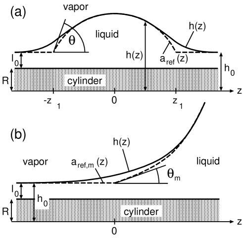
In cylindrical coordinates the droplet surface is described by a function or of the coordinate along the symmetry axis of the cylinder (Fig. 1(a)). We define and such that is the local separation between the liquid-vapor interface and the symmetry axis of the cylinder and is the local separation between the cylinder surface and the liquid-vapor interface, i.e., the liquid layer thickness. The droplet is also symmetric with respect to a reflection at the plane . For large values of , i.e., at large distances from the droplet center at , the liquid forms a thin wetting layer of thickness around the cylinder. For reasons of simplicity is henceforth assumed to be a unique function of , i.e., we do not consider contact angles . The shape of the liquid-vapor interface enclosing the droplet is determined by the interplay of three physical quantitites: the Laplace pressure [28] generated by the mean curvature of the interface with surface tension , the capillary pressure [28] induced by the finite droplet volume, and the disjoining pressure or, equivalently, the effective interface potential acting on the liquid-vapor interface [22]; is the cost in free energy per surface area to maintain a homogeneous wetting layer of prescribed thickness covering the cylinder surface and can be expressed in terms of the underlying forces of the substrate and between the fluid particles [29]. In the absence of the effective interface potential, i.e., for large droplets the liquid-vapor interface is a minimal surface under the constraint of a prescribed volume, i.e., it exhibits a constant mean curvature. The influence of the effective interface potential is most pronounced near the cylinder surface within the range of the substrate potential and leads to a deviation of the actual profile from the shape which is determined by the aforementioned constant mean curvature condition. On the other hand, in the limit of large separation from the cylinder surface the mean curvature is asymptotically constant because there the influence of the effective interface potential vanishes.
Independent of the size of the droplet, for later purposes we define the “reference configuration” (see Fig. 1(a))
| (1) |
where is that constant-mean-curvature surface which touches the surface , , and exhibits the same curvature at the apex, i.e., the two principal radii of curvature
| (2) |
and of and, correspondingly, of (see Fig. 1(a)) at the apex position are identical. denotes the Heaviside step function; are those values of where and the homogeneous wetting layer intersect. In this sense the values define the positions of the two three-phase contact lines forming the ends of the droplet. The “apparent contact angle” is defined by the intersection of the barrel-shaped part of the reference profile and the homogeneous wetting layer (see Fig. 1(a)):
| (3) |
This apparent contact angle can be expressed [1, 2] in terms of the measurable quantities apex height of the droplet, radius of the cylinder, radius of the wetting film, and radius of curvature (Eq. (2)) of the profile at the apex:
| (4) |
Within an interface displacement model (see, e.g., Ref. [30]) the equilibrium interface configuration for a droplet of prescribed excess volume minimizes the free energy functional
| (5) | |||||
| (6) |
under the constraint
| (7) |
and the boundary conditions . We have defined as an excess free energy with respect to the free energy of the homogeneous wetting layer rendering a mathematically well-defined, finite expression. The first contribution to is the excess free energy due to the increase of the liquid-vapor interface as compared with a homogeneous cylindrical shape. In general itself depends on the curvature and thus on (see, e.g., Sec. 2.2 in Ref. [29] and references therein); in the following, however, we do not discuss explicitly this additional parametric dependence on . The second contribution to is the free energy generated by the effective interaction between the cylinder surface and the liquid-vapor interface, reduced by the corresponding free energy for the homogeneous wetting layer. Since the substrate is considered to be homogeneous, depends only on the radial distance from the substrate surface. The equilibrium separation of the homogeneous wetting layer from the cylinder axis minimizes the free energy where is the macroscopic length of the cylinder. The constrained minimum of Eq. (5) is given by the unconstrained minimum of the surrogate functional
| (8) |
The corresponding optimal profile renders the equilibrium profile upon expressing the Lagrange multiplier in terms of by inserting into the left hand side of Eq. (7) which yields the implicit relation . In order to avoid a clumsy notation, in the following we denote by . The Euler-Lagrange equation corresponding to Eq. (8) reads
| (9) |
This equation describes the balance between the Laplace pressure on the left hand side and the capillary plus disjoining pressure on the right hand side. One has for any barrel-shaped droplet.
B Reference profiles
The reference profile minimizes a similar surrogate functional:
| (10) |
with the constant independent of and the boundary conditions . Equation (10) follows from Eq. (8) by omitting and replacing by . The corresponding Euler-Lagrange equation describes the constant-mean-curvature surface given by
| (11) |
According to the definition of the Lagrange multiplier has to be chosen such that this constant mean curvature of this surface equals the mean curvature at the apex of the actual surface :
| (12) |
(see Eq. (2)) and are the principal radii of curvature at the apex of the actual surface , determined by the former Lagrange multiplier . The solution of Eq. (11) is given implicitly by
| (13) |
which fulfils the boundary condition ; this determines implicitly in terms of , , , and . The integration constant is determined by due to the symmetry of . The integral in Eq. (13) can be expressed in terms of elliptic integrals [31, 32].
When the drop is macroscopicly large () it is appropriate to adopt a slightly different point of view. In this case not the center of the droplet but the position of one of the two three-phase contact lines, which are defined by the intersection of the asymptote (the constant-mean-curvature surface appertaining to the macroscopic drop) and , is fixed at (see Fig. 1(b)). The actual interface profile interpolates between, e.g., and . This configuration describes a solid cylinder which is in contact with bulk vapor on the left hand side () and with bulk liquid on the right hand side (). The analysis of the internal structure of a three-phase contact line on a homogeneous, planar substrate is based on a similar configuration (see Refs. [33] and [34] and references therein). The interface profile diverges in the limit : , but this divergence is not linear as in the case of the planar substrate. A macroscopicly large drop implies . In this limit the volume constraint loses its meaning. Instead the state of the system is fixed by different lateral boundary conditions. In this case the solution of Eq. (13) is given by
| (14) |
with two integration constants and . describes a rotational surface with minimal surface area. From Eq. (14) one can easily see that the divergence of the interface profile for macroscopic drops is exponential, , rather than linear as on a planar substrate. The reference profile appertaining to the macroscopic drop is
| (15) |
The slopes at the intersection of the asymptote and the homogeneous layer at defines the contact angle . corresponds to a planar substrate for which the interface profile diverges linearly in the limit :
| (16) |
with the macroscopic contact angle on the planar substrate. obeys Young’s law where and are the wall-gas and wall-liquid surface tensions, respectively; is determined by the effective interface potential of the corresponding planar substrate (see, c.f., Subsec. II C). On the cylindrical surface the contact angle does not follow from similar thermodynamic considerations but follows from the numerical analysis of the full profile for large (see, c.f., Sec. III and Fig. 9).
The integration constants and in Eq. (14) can be determined from the conditions and so that
| (17) |
The series expansion of this expression in terms of small is
| (18) |
In the limit the region where the higher order terms are relevant is shifted towards such that, with , one recovers the linearly diverging asymptote (Eq. (16)).
C Effective interface potential
For the same liquid layer thickness the effective interface potential of a cylinder differs from that of a planar substrate . The full expression is presented in Ref. [29] as obtained from density functional theory and within a so-called sharp-kink approximation for the solid-liquid and the liquid-vapor interface profiles. For reasons of simplicity, here we use the leading order of a series expansion of in terms of where is the radial extension of the volume excluded for the fluid particles due to the repulsive part of the substrate potential:
| (20) | |||||
with and hypergeometric functions. In the limit one recovers the expression for the effective interface potential of the corresponding planar substrate:
| (21) |
However, the power-law decay of for a fixed, finite cylinder radius is
| (22) |
i.e., one power faster than that for the corresponding planar substrate.
At present there exists, to our knowledge, only one study concerned with the shapes of droplets on cylinders within the range of the effective interface potential between the cylinder surface and the liquid-vapor interface [23]. However, in Ref. [23] the disjoining pressure on the right hand side of the Euler-Lagrange equation (9) as a whole rather than only the effective interface potential is replaced by the disjoining pressure of the corresponding planar substrate . In view of Eqs. (21) and (22), except for the factor , this corresponds to the short-distance expansion () of the effective interface potential of the cylinder. This replacement of the disjoining pressure by that of the planar substrate is expected to yield numerically reliable results only for large cylinder radii and small liquid layer thicknesses . Therefore in Sec. III we test the quality of this approximation (as well as that of the replacement of alone by ).
So far, due to the volume constraint, our considerations apply to nonvolatile liquids. For volatile liquids any droplet surrounded by a macroscopic reservoir of vapor phase is thermodynamically unstable against evaporation, leaving behind only the thin equilibrium wetting film. However, we expect that the actual nonequilibrium state of a condensating or evaporating liquid observed within a time scale that is small compared with the typical condensation or evaporation time can be described by solutions of Eq. (9) with given by its momentary value. Only the interface configuration for , i.e., , which interpolates between a homogeneous wetting layer and an exponentially diverging profile, describes a bona fide thermodynamically stable state which can be maintained by imposing appropriate boundary conditions (see above) at liquid-vapor coexistence for the bulk fluid. The thermodynamic state, which in a grand canonical ensemble is defined by temperature and chemical potential, enters parametrically into the actual values of the effective interface potential and the liquid-vapor surface tension .
III Shapes of droplet surfaces and contact angles
We solve the Euler-Lagrange equation (9) numerically for fixed values of and for a given effective interface potential ; the value of , in turn, determines the excess liquid volume and allows us to establish the relation . As boundary conditions in the case (leading to droplets of finite size) we use that must approach the wetting layer thickness for large and that . The distance , at which the system is cut off, is chosen large enough so that and attain their asymptotic values and , respectively, within prescribed accuracy. The reference profile is then calculated numerically by solving the differential equation (11) with determined by Eqs. (2) and (11) and with and , up to the point of intersection of and which defines the coordinate ; . The contact angle is determined from Eq. (3) and, as a crosscheck, from Eq. (4).
In all numerical calculations presented henceforth we set , , and such that sets the length scale for the range of the effective interface potential (typically nm). We divide both sides of Eq. (9) by so that is dimensionless and has the dimension of an inverse length. Alternatively, instead of introducing as above one can choose as the basic length scale which describes the decay of the effective interface potential; for our choice . The effective interface potentials (Eq. (20)) and (Eq. (21)) for the above choice of coefficients are shown in Fig. 2.
As a first example we solve Eq. (9) with the effective interface potential of the corresponding planar substrate (Eq. (21)) and the potential coefficients given above. Figure 3 shows the profile of the droplet surface on a cylinder with radius for . This choice of leads to a small droplet with (i.e., containing roughly fluid particles) whose liquid-vapor interface lies entirely within the range of the effective interface potential. Therefore the deviation of the profile from the asymptote extends up to the apex of the droplet. The model effective interface potential used here resembles a typical interface potential leading to first-order wetting on a planar substrate [22]. The droplet surface crosses the reference profile and, upon approaching the apex of the droplet, it reaches the reference profile from below.
Carroll [2] has shown that, in the absence of the effective interface potential, the axisymmetric droplet configuration is only stable for
| (23) |
i.e., if the droplet is large compared with the diameter of the cylinder and if the contact angle is small. When the droplet volume decreases or the contact angle increases the axisymmetric droplet becomes metastable against a so-called “roll up” towards the “clamshell” configuration [35]. Applying the stability criterion Eq. (23) to the interface profile shown in Fig. 3, we find that this barrel-type configuration is possibly metastable towards forming the “clamshell” shape. A definitive statement about the stability would require to refine the criterion in Eq. (23) by incorporating the effect of the effective interface potential. However, the determination of the non-axisymmetric “clamshell” equilibrium shape requires a much larger numerical effort and is therefore beyond the scope of the present paper. One can define a critical value such that for the axisymmetric droplet is stable. Upon increasing , increases, too; in the limit . Only for , i.e., for macroscopic drops, and for contact angles smaller than (as stated in Sec. II here we do not consider the case ) the rotationally symmetric interface shape is stable for any value of .
Figure 4 shows the droplet shape for the same choice of potential parameters and for the same cylinder with , but for . This choice of leads to a much bigger droplet with . The apex of the droplet is located at such a large distance from the cylinder surface that the effective interface potential is almost negligible. Therefore the application of Eq. (23) is reliable; it yields that this particular droplet is indeed stable against “roll-up”. In the vicinity of the cylinder surface the absolute deviation of the interface profile from the asymptote is similar to that in Fig. 3. As compared with the situation shown in Fig. 3, the point where crosses the reference profile is shifted to the right and lies near the three-phase contact line at . For the model effective interface potential used here and in Fig. 3, in the region around the apex of the droplet the profile lies below the reference profile. These results are in accordance with the findings for the planar, homogeneous substrate [33, 34] with the same type of interface potential. If, on the other hand, corresponds to a system undergoing a continuous wetting transition, i.e., exhibiting a single minimum without a potential barrier, the profile of the droplet shape approaches its asymptote from the outside without crossing it (see Fig. 8 in Ref. [34]).
Figure 5 displays the effect of the replacement of the effective interface potential of a cylinder (Eq. (20)) by that of the corresponding planar substrate (Eq. (21)) for a droplet with so that and on a thin cylinder with . This droplet also satisfies the stability criterion in Eq. (23). For reasons of clarity in this figure we have plotted the difference between corresponding profiles instead of the profiles themselves. The influence of approximating by turns out to be rather small: the difference is at most of the order of . It is even smaller in the case of smaller droplets and thicker cylinders: the quality of approximating by improves if the cylinder is thicker and the droplet is smaller. In Ref. [23] the disjoining pressure of a cylinder rather than the effective interface potential is replaced by its planar-substrate counterpart. This corresponds to replacing the term on the right hand side of Eq. (9) by . The dashed line in Fig. 5 shows the effect of this approximation on the surface profile. As expected, the quality of this approximation is worse than the substitution of the effective interface potential alone, although the difference is still of the order of .
Figure 6 shows the apparent contact angles for the examples presented in Figs. 3 and 4, as well as for the same set of potential parameters but with , , and as function of the excess liquid volume . Upon increasing the curves are shifted upwards and to the right. Due to the exponential divergence of the interface profile of a macroscopic drop (which is more pronounced for smaller , see the discussion of Eqs. (17) and (18) above and, c.f., Fig. 8), the determination of the apparent contact angles for very large drops is, in particular for thin cylinders, numerically difficult. However, the data indicate that, for any value of , is a monotonously decreasing function, with a vanishing slope at . The differences between the contact angles for different are minimal at . For any there is a sizeable increase of the apparent contact angle upon decreasing droplet size.
Figure 7 shows the effect of replacing by on the apparent contact angles for the system with (compare Fig. 5). The difference between the contact angles calculated by using and is significant. It is much smaller for thicker cylinders whose contact angles are displayed in Fig. 6. However, the qualitative functional form of the dependence of is not affected by the replacement of by .
For macroscopic drops (i.e., or, equivalently, ) the Euler-Lagrange equation is solved with the initial value and a small initial slope (e.g., ); the initial slope would yield the trivial solution . In order to find the asymptote we determine the integration constants and in Eq. (14) such that and where is the coordinate up to which the differential equation is integrated numerically; the system size is chosen large enough so that upon further increase of the system size and remain unchanged within prescribed accuracy. The contact angle can be inferred from the value of (Eq. (17)). Finally the coordinate system is shifted laterally such that the intersection of and define the position (which corresponds to for ). As mentioned before, for macroscopic drops the rotationally symmetric configuration satisfies the stability criterion Eq. (23) for any .
The dependence of the liquid-vapor interface profiles of macroscopic drops on the cylinder radius is shown in Fig. 8 using and with the same set of interaction potential parameters as in the previous examples. In accordance with Eq. (17), the interface profiles for cylinders of finite thickness diverge exponentially in the limit . In the limit the region where higher-order corrections to the linear behavior (Eq. (18)) are relevant is shifted towards such that in the limiting case corresponding to the planar substrate the linear divergence of the reference profile is recovered. Figure 9(a) displays the apparent contact angles corresponding to the profiles shown in Fig. 8 as function of . Upon increasing the cylinder radius , approaches Young’s contact angle for the planar substrate as .
In Fig. 9(b) we show the apparent contact angles of small droplets on a planar substrate, i.e., in the limit but with . In this case the reference configuration is a spherical cap whose circular base has a radius (see Fig. 1(a)). For large droplets reaches Young’s contact angle according to the Neumann-Boruvka equation [28, 36]
| (24) |
which allows one to determine experimentally the line tension of three-phase contact on a planar substrate by varying the droplet size. Figure 9(b) demonstrates that this linear relationship between and is valid only for , i.e., for nm. From Fig. 9(b) one infers that decreases more rapidly than predicted by Eq. (24). This behavior can be accounted for by an effective line tension which due to the circular bending of the three-phase contact line is larger than the value of the corresponding straight three-phase contact line. Similar results have been obtained by Dobbs [37].
IV Line tension
As long as the size of a droplet is finite and fixed it is impossible to extract from the total free energy unambiguously and in a strict thermodynamic sense a line tension associated with the three-phase contact lines at the ends of the droplet because there are arbitrarily many ways to form the total free energy as a sum of various terms. However, well-defined line tensions emerge as coefficients in the size dependence of the free energy of droplets upon approaching macroscopic drops. To this end we consider the limit of large drops, i.e., and (see Fig. 1(a)). Within the interface displacement model the excess free energy in Eq. (5) can be rewritten as
| (25) |
where
| (26) |
is the surface area of the “barrel” part of the reference surface , , is the surface area of the cylinder with radius and length (see Fig. 1(a)), and
| (28) | |||||
For , (Eq. (25)) is dominated by the term which scales proportional to the surface area of the drop and thus represents a two-dimensional contribution. The leading subdominant terms are and , which scale with the linear dimension of the drop representing one-dimensional contributions. Finally, the last term in Eq. (25) remains finite for , , and :
| (29) |
and thus represents a zero-dimensional contribution. In its turn depends on the cylinder radius such that for large it scales proportional to which leads to the following definition of an excess free energy per unit length, henceforth called “line tension”, associated with the two contact lines formed at the ends of the droplet with total length :
| (30) |
We note that is only well-defined in the thermodynamic limit so that higher order terms, e.g., , omitted on the right hand side of Eq. (29) drop out. In the following is understood to have been obtained via this procedure. It can be expressed in terms of the solution of Eq. (9) for and of (Eqs. (14) and (15)):
| (32) | |||||
Consequently, is twice the characteristic excess free energy associated with the structure of a macroscopic drop near one of its ends without interference from the other end. On the other hand, , and thus , are defined for any value of . The ratio formed in Eq. (30) has the property that in the limit it reduces to the line tension of the straight three-phase contact line on the corresponding planar substrate (see, e.g., Refs. [30, 33, 34, 38]), which is an experimentally observable quantity (compare Fig. 9(b)).
At this stage one should note that the above considerations tacitly assume that another thermodynamic limit concerning the total system size, such as the volume of the surrounding vapor phase and the length of the solid cylinder, has already been carried out in advance: is proportional to and has been subtracted before. Moreover, we have not considered the bulk free energy of the surrounding vapor phase and the bulk free energy of the liquid in the drop proportional to because they do not enter the description of the droplet shape in terms of an interface displacement model. As a careful analysis of the line tension within density functional theory for a volatile liquid at gas-liquid coexistence shows, in comparison with this more complete theory the interface displacement model misses a contribution which is independent of the shape and is determined by and (the first term in the sum in Eq. (2.19) in Ref. [34], denoted as in Eqs. (4.2), (4.3), and (4.5) in Ref. [33]). Since, however, this constant contribution turns out to be numerically much smaller than those contributions captured by the interface displacement model (see Fig. 15 in Ref. [33]), we have refrained from determining it for the present, much more complicated geometry, assuming that the size ratios of these types of contributions remain roughly the same for the planar and the cylindrical substrate.
Figure 10 shows the dependence of the line tension on the cylinder radius using the planar effective interface potential . is given by times a numerical factor of the order of 1. It decreases monotonously for decreasing and attains its maximum value for as . We note that this decrease of the line tension upon decreasing the radius of curvature of the contact line is opposite to the increase of the effective line tension observed for a decreasing radius of curvature of the circular three-phase contact line on a planar substrate as can be inferred from Fig. 9(b). Thus line tensions of curved three-phase contact lines can be smaller or larger than the line tension of the corresponding straight contact lines.
Whereas is experimentally accessible by monitoring the apparent contact angle of sessile droplets on a planar substrate as function of the droplet size, cannot be determined experimentally by direct observation. The basic reason for this difference is that the length of the three-phase contact line of the sessile drop on the planar substrate can vary as function of the droplet size so that the optimal shape of the droplet responds to the associated cost of the free energy, whereas the excess free energy for the ends of the droplets is a constant contribution with respect to the droplet size on the cylinder due to the fixed value of . This, however, holds only for the “barrel”-type shape of the drop, for which the length of the three-phase contact lines is fixed. For “clamshell”-type droplet shapes the length of the three-phase contact line does depend on the droplet size so that in this case the line tension will influence the droplet shape. Nonetheless there are systems for which can be experimentally relevant. If the cylinder is not a hard solid rod but consists of a soft material like, e.g., vesicles or tobacco viruses which float vertically at the liquid-vapor interface of a solvent, the positive line tension will strangle the object locally, depending on its restoring elastic forces. According to Fig. 10 this tweaking force is weaker for thin cylinders.
V Summary
Based on an interface displacement model (Eq. (5)) we have analyzed the shape and the free energy of “barrel”-type droplets of fixed volume covering a cylindrical substrate of radius (Fig. 1). For sufficiently small droplets their shape is not only governed by the surface tension of the liquid-vapor interface but also by the effective interface potential with a generic form as shown in Fig. 2. We have obtained the following main results:
-
1.
Figures 3 and 4 show how the deviation of the actual droplet shape from a suitably defined reference configuration depends on the droplet size. The reference configuration is uniquely defined by the requirement to touch the actual shape at the apex and to have a constant mean curvature which equals the actual one at the apex. allows one to introduce an apparent contact angle , characterizing the actual shape, which can be expressed in terms of the experimentally accessible quantities cylinder radius , radii of curvature at the apex, height of the droplet, and thickness of the wetting layer outside the barrel (Eq. (4)).
- 2.
- 3.
-
4.
In the limiting case of small droplets on a planar substrate the circular bend of the three-phase contact line leads to an effectively increased value of the corresponding line tension (Fig. 9(b)). This deviation from the Neumann-Boruvka equation becomes relevant if the droplet radius is less than roughly nm. This observation is relevant for experimental determinations of line tensions via contact angle measurements.
- 5.
-
6.
For large cylinder radii the line tension associated with the ends of macroscopicly large drops approaches the line tension of three-phase contact on a planar substrate proportional to (Fig. 10).
Acknowledgements.
This work has been supported by the German Science Foundation within the Special Research Initiative Wetting and Structure Formation at Interfaces.REFERENCES
- [1] B. J. Carroll, J. Colloid Interface Sci. 97, 195 (1984).
- [2] B. J. Carroll, Langmuir 2, 248 (1986).
- [3] B. J. Carroll, in Contact Angle, Wettability and Adhesion, edited by K. L. Mittal (VSP, Utrecht, 1993), p. 235; J. Appl. Phys. 70, 493 (1991).
- [4] P. Levinson, J. Jouffroy, and F. Brochard, J. Physique Lett. 46, L21 (1985); F. Brochard, J. Chem. Phys. 84, 4664 (1986).
- [5] D. Quéré, J.-M. di Meglio, and F. Brochard-Wyart, Revue Phys. Appl. 23, 1023 (1988); Europhys. Lett. 10, 335 (1989); Science 249, 1256 (1990), and references therein; A. de Ryck and D. Quéré, C. R. Acad. Sci. Paris, Série II 316, 1045 (1993); ibid 317, 891 (1993); V. I. Ivanov, D. Quéré, J.-M. di Meglio, and V. M. Starov, Colloid J. Russian Acad. Sci. 54, 346 (1992); D. Quéré and J.-M. di Meglio, Adv. Colloid Interface Sci. 48, 141 (1994).
- [6] S. Rooks, L. M. Racz, J. Szekely, B. Benhabib, and A. W. Neumann, Langmuir 7, 3222 (1991).
- [7] H. D. Wagner, J. Appl. Phys. 67, 1352 (1990); ibid 70, 495 (1991).
- [8] A. L. Yarin, A. Oron, and P. Rosenau, Phys. Fluids A5, 91 (1993).
- [9] Y.-N. Lee and S.-M. Chiao, J. Colloid Interface Sci. 181, 378 (1996).
- [10] M. Connor, P. H. Harding, J.-A. E. Månson, and J. C. Berg, J. Adhesion Sci. Technol. 9, 983 (1995).
- [11] G. McHale, N. A. Käb, M. I. Newton, and S. M. Rowan, J. Colloid Interface Sci. 186, 453 (1997). G. McHale, S. M. Rowan, M. I. Newton, and N. A. Käb, J. Adhesion Sci. Technol. 13, 1457 (1999).
- [12] J. R. de Bruyn, Phys. Fluids 9, 1599 (1997).
- [13] B. Song, A. Bismarck, R. Tahhan, and J. Springer, J. Colloid Interface Sci. 197, 68 (1998).
- [14] Y. Gu and D. Li, J. Colloid Interface Sci. 206, 288 (1998).
- [15] L. M. Jenkins and A. M. Donald, Langmuir 15, 7829 (1999).
- [16] E. Dujardin, T. W. Ebbesen, A. Krishnan, and M. M. J. Treacy, Adv. Mat. 10, 1472 (1998).
- [17] P. M. Ajayan, O. Stephan, P. Redlich, and C. Collex, Nature 375, 564 (1995).
- [18] T. W. Ebbesen, H. Hiura, M. E. Bisher, M. M. J. Treacy, J. L. Shreeve-Keyer, and R. C. Haushalter, Adv. Mat. 8, 155 (1996).
- [19] E. Dujardin, T. W. Ebbesen, H. Hiura, and K. Tanigaki, Science 265, 1850 (1994).
- [20] T. Kasuga, M. Hiramatsu, A. Hoson, T. Sekino, and K. Niihara, Langmuir 14, 3160 (1998).
- [21] P. Kim and C. M. Lieber, Science 286, 2148 (1999).
- [22] S. Dietrich, in Phase Transitions and Critical Phenomena, edited by C. Domb and J. L. Lebowitz (Academic, London, 1988), Vol. 12, p. 1.
- [23] A. Neimark, J. Adhesion Sci. Technol. 13, 1137 (1999).
- [24] J. Y. Wang, S. Betelu, and B. M. Law, Phys. Rev. Lett 83, 3677 (1999).
- [25] K. R. Neumaier, G. Elender, E. Sackmann, and R. Merkel, Europhys. Lett. 49, 14 (2000).
- [26] F. Rieutord and M. Salmeron, J. Phys. Chem. B 102, 3941 (1998).
- [27] S. Herminghaus, A. Fery, and D. Reim, Ultramicroscopy 69, 211 (1997); T. Pompe, A. Fery, and S. Herminghaus, Langmuir 14, 2585 (1998); A. Fery, T. Pompe, and S. Herminghaus, J. Adhesion Sci. Technol. 13, 1071 (1999); T. Pompe, A. Fery, and S. Herminghaus, J. Adhesion Sci. Technol. 13, 1155 (1999); T. Pompe and S. Herminghaus, University of Ulm preprint (1999).
- [28] J. S. Rowlinson and B. Widom, Molecular Theory of Capillarity (Clarendon, Oxford, 1982).
- [29] T. Bieker and S. Dietrich, Physica A 252, 85 (1998); ibid 259, 466 (1998).
- [30] J. O. Indekeu, Int. J. Mod. Phys. B 8, 309 (1994).
- [31] B. J. Carroll, J. Colloid Interface Sci. 57, 488 (1976).
- [32] J. Yamaki and Y. Katayama, J. Appl. Polym. Sci. 19, 2897 (1975).
- [33] T. Getta and S. Dietrich, Phys. Rev. E 57, 655 (1998).
- [34] C. Bauer and S. Dietrich, Eur. Phys. J. B 10, 767 (1999).
- [35] N. K. Adam, J. Soc. Dyers Colour. 53, 122 (1937).
- [36] L. Boruvka and A. W. Neumann, J. Phys. Chem. 66, 5464 (1977).
- [37] H. Dobbs, Int. J. Mod. Phys. B 13, 3255 (1999).
- [38] H. T. Dobbs and J. O. Indekeu, Physica A 201, 457 (1993).