Computer Simulations of Friction, Lubrication and Wear
(To appear in the Handbook of Modern Tribology edited by Bharat Bhushan
(CRC Press))
| Mark O. Robbins | Martin H. Müser |
| Dept. of Physics and Astronomy | Institut für Physik, WA 311 |
| The Johns Hopkins University | Johannes Gutenberg-Universität |
| 3400 N. Charles St. | 55 099 Mainz |
| Baltimore, MD 21218 | GERMANY |
| USA |
I Introduction
Computer simulations have played an important role in understanding tribological processes. They allow controlled numerical ”experiments” where the geometry, sliding conditions and interactions between atoms can be varied at will to explore their effect on friction, lubrication, and wear. Unlike laboratory experiments, computer simulations enable scientists to follow and analyze the full dynamics of all atoms. Moreover, theorists have no other general approach to analyze processes like friction and wear. There is no known principle like minimization of free energy that determines the steady state of non-equilibrium systems. Even if there was, simulations would be needed to address the complex systems of interest, just as in many equilibrium problems.
Tremendous advances in computing hardware and methodology have dramatically increased the ability of theorists to simulate tribological processes. This has led to an explosion in the number of computational studies over the last decade, and allowed increasingly sophisticated modeling of sliding contacts. Although it is not yet possible to treat all the length scales and time scales that enter the friction coefficient of engineering materials, computer simulations have revealed a great deal of information about the microscopic origins of static and kinetic friction, the behavior of boundary lubricants, and the interplay between molecular geometry and tribological properties. These results provide valuable input to more traditional macroscopic calculations. Given the rapid pace of developments, simulations can be expected to play an expanding role in tribology.
In the following chapter we present an overview of the major results from the growing simulation literature. The emphasis is on providing a coherent picture of the field, rather than a historical review. We also outline opportunities for improved simulations, and highlight unanswered questions.
We begin by presenting a brief overview of simulation techniques and focus on special features of simulations for tribological processes. For example, it is well known that the results of tribological experiments can be strongly influenced by the mechanical properties of the entire system that produces sliding. In much the same way, the results from simulations depend on how relative motion of the surfaces is imposed, and how heat generated by sliding is removed. The different techniques that are used are described, so that their influence on results can be understood in later sections.
The complexities of realistic three-dimensional systems can make it difficult to analyze the molecular mechanisms that underly friction. The third section focuses on dry, wearless friction in less complex systems. The discussion begins with simple one-dimensional models of friction between crystalline surfaces. These models illustrate general results for the origin and trends of static and kinetic friction, such as the importance of metastability and the effect of commensurability. Then two-dimensional studies are described, with an emphasis on the connection to atomic force microscope experiments and detailed measurements of the friction on adsorbed monolayers.
In the fourth section, simulations of the dry sliding of crystalline surfaces are addressed. Studies of metal/metal interfaces, surfactant coated surfaces, and diamond interfaces with various terminations are described. The results can be understood from the simple pictures of the previous chapter. However, the extra complexity of the interactions in these systems leads to a richer variety of processes. Simple examples of wear between metal surfaces are also discussed.
The fifth section describes how the behavior of lubricated systems begins to deviate from bulk hydrodynamics as the thickness of the lubricant decreases to molecular scales. Deviations from the usual no-slip boundary condition are found in relatively thick films. These are described, and correlated to structure induced in the lubricant by the adjoining walls. As the film thickness decreases, the effective viscosity increases rapidly above the bulk value. Films that are only one or two molecules thick typically exhibit solid behavior. The origins of this liquid/solid transition are discussed, and the possibility that thin layers of adventitious carbon are responsible for the prevalence of static friction is explored. The section concludes with descriptions of simulations using realistic models of hydrocarbon boundary lubricants between smooth and corrugated sufaces.
The sixth section describes work on the common phenomenon of stick-slip motion, and microscopic models for its origins. Atomic-scale ratcheting is contrasted with long-range slip events, and the structural changes that accompany stick-slip transitions in simulations are described.
The seventh and final section describes work on friction at extreme conditions such as high shear rates or large contact pressures. Simulations of tribochemical reactions, machining, and the evolution of microstructure in sliding contacts are discussed.
II Atomistic Computer Simulations
The simulations described in this chapter all use an approach called classical molecular dynamics (MD) that is described extensively in a number of review articles and books, including Allen and Tildesley (1987) and Frenkel and Smit (1996). The basic outline of the method is straightforward. One begins by defining the interaction potentials. These produce forces on the individual particles whose dynamics will be followed, typically atoms or molecules. Next the geometry and boundary conditions are specified, and initial coordinates and velocities are given to each particle. Then the equations of motion for the particles are integrated numerically, stepping forward in time by discrete steps of size . Quantities such as forces, velocities, work, heat flow, and correlation functions are calculated as a function of time to determine their steady-state values and dynamic fluctuations. The relation between changes in these quantities and the motion of individual molecules is also explored.
When designing a simulation, care must be taken to choose interaction potentials and ensembles that capture the essential physics that is to be addressed. The potentials may be as simple as ideal spring constants for studies of general phenomena, or as complex as electronic density-functional calculations in quantitative simulations. The ensemble can also be tailored to the problem of interest. Solving Newton’s equations yields a constant energy and volume, or microcanonical, ensemble. By adding terms in the equation of motion that simulate heat baths or pistons, simulations can be done at constant temperature, pressure, lateral force, or velocity. Constant chemical potential can also be maintained by adding or removing particles using Monte Carlo methods or explicit particle baths.
The amount of computational effort typically grows linearly with both the number of particles, , and the number of time-steps . The prefactor increases rapidly with the complexity of the interactions, and substantial ingenuity is required to achieve linear scaling with for long-range interactions or density-functional approaches. Complex interactions also lead to a wide range of characteristic frequencies, such as fast bond-stretching and slow bond-bending modes. Unfortunately, the time step must be small ( 2%) compared to the period of the fastest mode. This means that many time steps are needed before one obtains information about the slow modes.
The maximum feasible simulation size has increased continuously with advances in computer technology, but remains relatively limited. The product of times in the largest simulations described below is about . A cubic region of atoms would have a side of about 50nm. Such linear dimensions allow reasonable models of an atomic force microscope tip, the boundary lubricant in a surface force apparatus, or an individual asperity contact on a rough surface. However time steps is only about 10 nanoseconds, which is much smaller than experimental measurement times. This requires intelligent choices in the problems that are attacked, and how results are extrapolated to experiment. It also limits sliding velocities to relatively high values, typically meters per second or above.
A number of efforts are underway to increase the accessible time scale, but the problem remains unsolved. Current algorithms attempt to follow the deterministic equations of motion, usually with the Verlet or predictor-corrector algorithms (Allen and Tildesley, 1987). One alternative approach is to make stochastic steps. This would be a non-equilibrium generalization of the Monte Carlo approach that is commonly used in equilibrium systems. The difficulty is that there is no general principle for determining the appropriate probability distribution of steps in a non-equilibrium system.
In the following we describe some of the potentials that are commonly used, and the situations where they are appropriate. The final two subsections describe methods for maintaining constant temperature and constant load.
A Model Potentials
A wide range of potentials has been employed in studies of tribology. Many of the studies described in the next section use simple ideal springs and sine-wave potentials. The Lennard-Jones potential gives a more realistic representation of typical inter-atomic interactions, and is also commonly used in studies of general behavior. In order to model specific materials, more detail must be built into the potential. Simulations of metals frequently use the embedded atom method, while studies of hydrocarbons use potentials that include bond-stretching, bending, torsional forces and even chemical reactivity. In this section we give a brief definition of the most commonly used models. The reader may consult the original literature for more detail.
The Lennard-Jones (LJ) potential is a two-body potential that is commonly used for interactions between atoms or molecules with closed electron shells. It is applied not only to the interaction between noble gases, but also to the interaction between different segments on polymers. In the latter case, one LJ particle may reflect a single atom on the chain (explicit atom model), a CH2 segment (united atom model) or even a Kuhn’s segment consisting of several CH2 units (coarse-grained model). United atom models (Ryckaert and Bellemans, 1978) have been shown by Paul et al. (1995) to successfully reproduce explicit atom results for polymer melts, while Tschöp et al. (1998a, 1998b) have successfully mapped chemically detailed models of polymers onto coarse-grained models and back.
The 12-6 LJ potential has the form
| (1) |
where is the distance between particles and , is the LJ interaction energy, and is the LJ interaction radius. The exponents 12 and 6 used above are very common, but depending on the system, other values may be chosen. Many of the simulation results discussed in subsequent sections are expressed in units derived from , , and a characteristic mass of the particles. For example, the standard LJ time unit is defined as , and would typically correspond to a few picoseconds. A convenient time step is for a LJ liquid or solid at external pressures and temperatures that are not too large.
Most realistic atomic potentials can not be expressed as two-body potentials. For example, bond angle potentials in a polymer are effectively three-body interactions and torsional potentials correspond to four-body interactions. Classical models of these interactions (Flory, 1988; Binder, 1995) assume that a polymer is chemically inert and interactions between different molecules are modeled by two-body potentials. In the most sophisticated models, bond-stretching, bending and torsional energies depend on the position of neighboring molecules and bonds are allowed to rearrange (Brenner, 1990). Such generalized model potentials are needed to model friction-induced chemical interactions.
For the interaction between metals, a different approach has proven fruitful. The embedded atom method (EAM), introduced by Daw and Baskes (1984), includes a contribution in the potential energy associated with the cost of ”embedding” an atom in the local electron density produced by surrounding atoms. The total potential energy is approximated by
| (2) |
where is the embedding energy, whose functional form depends on the particular metal. The pair potential is a doubly-screened short-range potential reflecting core-core repulsion. The computational cost of the EAM is not substantially greater than pair potential calculations because the density is approximated by a sum of independent atomic densities. When compared to simple two-body potentials such as Lennard-Jones or Morse potentials, the EAM has been particularly successful in reproducing experimental vacancy formation energies and surface energies, even though the potential parameters were only adjusted to reproduce bulk properties. This feature makes the EAM an important tool in tribological applications, where surfaces and defects play a major role.
B Maintaining Constant Temperature
An important issue for tribological simulations is temperature regulation. The work done when two walls slide past each other is ultimately converted into random thermal motion. The temperature of the system would increase indefinitely if there was no way for this heat to flow out of the system. In an experiment, heat flows away from the sliding interface into the surrounding solid. In simulations, the effect of the surrounding solid must be mimicked by coupling the particles to a heat bath.
Techniques for maintaining constant temperature in equilibrium systems are well-developed. Equipartition guarantees that the average kinetic energy of each particle along each Cartesian coordinate is where is Boltzmann’s constant.*** This assumes that is above the Debye temperature so that quantum statistics are not important. The applicability of classical MD decreases at lower . To thermostat the system, the equations of motion are modified so that the average kinetic energy stays at this equilibrium value.
One class of approaches removes or adds kinetic energy to the system by multiplying the velocities of all particles by the same global factor. In the simplest version, velocity rescaling, the factor is chosen to keep the kinetic energy exactly constant at each time step. However, in a true constant temperature ensemble there would be fluctuations in the kinetic energy. Improvements, such as the Berendsen and Nosé-Hoover methods (Nosé, 1991) add equations of motion that gradually scale the velocities to maintain the correct average kinetic energy over a longer time scale.
Another approach is to couple each atom to its own local thermostat (Schneider and Stoll, 1978; Grest and Kremer, 1986). The exchange of energy with the outside world is modeled by a Langevin equation that includes a damping coefficient and a random force on each atom . The equations of motion for the component of the position become:
| (3) |
where is the total potential energy and is the mass of the atom. To produce the appropriate temperature, the forces must be completely random, have zero mean, and have a second moment given by
| (4) |
The damping coefficient must be large enough that energy can be removed from the atoms without substantial temperature increases. However, it should be small enough that the trajectories of individual particles are not perturbed too strongly.
The first issue in non-equilibrium simulations is what temperature means. Near equilibrium, hydrodynamic theories define a local temperature in terms of the equilibrium equipartition formula and the kinetic energy relative to the local rest frame (Sarman et al., 1998). In dimensions, the definition is
| (5) |
where the sum is over all particles and is the mean velocity in a region around . As long as the change in mean velocity is sufficiently slow, is well-defined, and this definition of temperature is on solid theoretical ground.
When the mean velocity difference between neighboring molecules becomes comparable to the random thermal velocities, temperature is not well-defined. An important consequence is that different strategies for defining and controlling temperature give very different structural order and friction forces (Evans and Morriss, 1986; Loose and Ciccotti, 1992; Stevens and Robbins, 1993). In addition, the distribution of velocities may become non-Gaussian, and different directions may have different effective temperatures. Care should be taken in drawing conclusions from simulations in this extreme regime. Fortunately, the above condition typically implies that the velocities of neighboring atoms differ by something approaching 10% of the speed of sound. This is generally higher than any experimental velocity, and would certainly lead to heat buildup and melting at the interface.
In order to mimic experiments, the thermostat is often applied only to those atoms that are at the outer boundary of the simulation cell. This models the flow of heat into surrounding material that is not included explicitly in the simulation. The resulting temperature profile is peaked at the shearing interface (e.g. Bowden and Tabor, 1986; Khare et al., 1996). In some cases the temperature rise may lead to undesirable changes in the structure and dynamics even at the lowest velocity that can be treated in the available simulation time. In this case, a weak thermostat applied throughout the system may maintain the correct temperature and yield the dynamics that would be observed in longer simulations at lower velocities. The safest course is to couple the thermostat only to those velocity components that are perpendicular to the mean flow. This issue is discussed further in Sec. III E.
There may be a marginal advantage to local Langevin methods in non-equilibrium simulations because they remove heat only from atoms that are too hot. Global methods like Nosé-Hoover remove heat everywhere. This can leave high temperatures in the region where heat is generated, while other regions are at an artificially low temperature.
C Imposing Load and Shear
The magnitude of the friction that is measured in an experiment or simulation may be strongly influenced by the way in which the normal load and tangential motion are imposed (Rabinowicz, 1965). Experiments almost always impose a constant normal load. The mechanical system applying shear can usually be described as a spring attached to a stage moving at controlled velocity. The effective spring constant includes the compliance of all elements of the loading device, including the material on either side of the interface. Very compliant springs apply a nearly constant force, while very stiff springs apply a nearly constant velocity.
In simulations, it is easiest to treat the boundary of the system as rigid, and to translate atoms in this region at a constant height and tangential velocity. However this does not allow atoms to move around (Sec. III D) or up and over atoms on the opposing surface. Even the atomic-scale roughness of a crystalline surface can lead to order of magnitude variations in normal and tangential force with lateral position when sliding is imposed in this way (Harrison et al., 1992b, 1993; Robbins and Baljon, 2000). The difference between constant separation and pressure simulations of thin films can be arbitrarily large, since they produce different power law relations between viscosity and sliding velocity (Sec. V B).
One way of minimizing the difference between constant separation and pressure ensembles is to include a large portion of the elastic solids that bound the interface. This extra compliance allows the surfaces to slide at a more uniform normal and lateral force. However, the extra atoms greatly increase the computational effort.
To simulate the usual experimental ensemble more directly, one can add equations of motion that describe the position of the boundary (Thompson et al., 1990b, 1992, 1995), much as equations are added to maintain constant temperature. The boundary is given an effective mass that moves in response to the net force from interactions with mobile atoms and from the external pressure and lateral spring. The mass of the wall should be large enough that its dynamics are slower than those of individual atoms, but not too much slower, or the response time will be long compared to the simulation time. The spring constant should also be chosen to produce an appropriate response time and ensemble.
III Wearless Friction in Low Dimensional Systems
A Two Simple Models of Crystalline Surfaces in Direct Contact
Static and kinetic friction involve different aspects of the interaction between surfaces. The existence of static friction implies that the surfaces become trapped in a local potential energy minimum. When the bottom surface is held fixed, and an external force is applied to the top surface, the system moves away from the minimum until the derivative of the potential energy balances the external force. The static friction is the maximum force the potential can resist, i.e. the maximum slope of the potential. When this force is exceeded, the system begins to slide, and kinetic friction comes in to play. The kinetic friction is the force required to maintain sliding at a given velocity . The rate at which work is done on the system is and this work must be dissipated as heat that flows away from the interface. Thus simulations must focus on the nature of potential energy minima to probe the origins of static friction, and must also address dissipation mechanisms to understand kinetic friction.
Two simple ball and spring models are useful in illustrating the origins of static and kinetic friction, and in understanding the results of detailed simulations. Both consider two clean, flat, crystalline surfaces in direct contact (Fig. 1a). The bottom solid is assumed to be rigid, so that it can be treated as a fixed periodic substrate potential acting on the top solid. In order to make the problem analytically tractable, only the bottom layer of atoms from the top solid is retained, and the interactions within the top wall are simplified. In the Tomlinson model (Fig. 1b), the atoms are coupled to the center of mass of the top wall by springs of stiffness , and coupling between neighboring atoms is ignored (Tomlinson, 1929; McClelland and Cohen, 1990). In the Frenkel-Kontorova model (Fig. 1c), the atoms are coupled to nearest-neighbors by springs, and the coupling to the atoms above is ignored (Frenkel and Kontorova, 1938). Due to their simplicity, these models arise in a number of different problems and a great deal is known about their properties. McClelland (1989) and McClelland and Glosli (1992) have provided two early discussions of their relevance to friction. Bak (1982) has reviewed the Frenkel-Kontorova model and the physical systems that it models in different dimensions.

B Metastability and Static Friction in One Dimension
Many features of the Tomlinson and Frenkel-Kontorova models can be understood from their one-dimensional versions. One important parameter is the ratio between the lattice constants of the two surfaces . The other is the strength of the periodic potential from the substrate relative to the spring stiffness that represents interactions within the top solid. If the substrate potential has a single Fourier component, then the periodic force can be written as
| (6) |
The relative strength of the potential and springs can be characterized by the dimensionless constant .
In the limit of infinitely strong springs (), both models represent rigid solids. The atoms of the top wall are confined to lattice sites , where the integer labels successive atoms, and represents a rigid translation of the entire wall. The total lateral or friction force is given by summing Eq. 6
| (7) |
where is the number of atoms in the top wall. In the special case of equal lattice constants (), the forces on all atoms add in phase, and . The maximum of this restraining force gives the static friction .
Unless there is a special reason for and to be related, is most likely to be an irrational number. Such surfaces are called incommensurate, while surfaces with a rational value of are commensurate. When is irrational, atoms on the top surface sample all phases of the periodic force with equal probability and the net force (Eq. 7) vanishes exactly.
When is a rational number, it can be expressed as where and are integers with no common factors. In this case, atoms only sample different phases. The net force from Eq. 7 still vanishes because the force is a pure sine wave and the phases are equally spaced. However, the static friction is finite if the potential has higher harmonics. A Fourier component with wavevector and magnitude contributes to . Studies of surface potentials (Bruch et al., 1997) show that drops exponentially with increasing and thus imply that will only be significant for small .
As the springs become weaker, the top wall is more able to deform into a configuration that lowers the potential energy. The Tomlinson model is the simplest case to consider, because each atom can be treated as an independent oscillator within the upper surface. The equations of motion for the position of the atom can be written as
| (8) |
where is the atomic mass and is the position of the lattice site. Here is a phenomenological damping coefficient, like that in a Langevin thermostat (Sec. II B), that allows work done on the atom to be dissipated as heat. It represents the coupling to external degrees of freedom such as lattice vibrations in the solids.
In any steady-state of the system, the total friction can be determined either from the sum of the forces exerted by the springs on the top wall, or from the sum of the periodic potentials acting on the atoms (Eq. 7). If the time average of these forces differed, there would be a net force on the atoms and a steady acceleration (Thompson and Robbins, 1990a; Matsukawa and Fukuyama, 1994). The static friction is related to the force in metastable states of the system where . This requires that spring and substrate forces cancel for each ,
| (9) |
As shown graphically in Fig. 2a, there is only one solution for weak interfacial potentials and stiff solids (). In this limit, the behavior is essentially the same as for infinitely rigid solids. There is static friction for , but not for incommensurate cases. Even though incommensurate potentials displace atoms from lattice sites, there are exactly as many displaced to the right as to the left, and the force sums to zero.
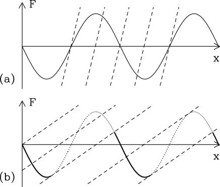
A new type of behavior sets in when exceeds unity. The interfacial potential is now strong enough compared to the springs that multiple metastable states are possible. These states must satisfy both Eq. 9 and the condition that the second derivative of the potential energy is positive: . The number of metastable solutions increases as increases.
As illustrated in Fig. 2b, once an atom is in a given metastable minimum it is trapped there until the center of mass moves far enough away that the second derivative of the potential vanishes and the minimum becomes unstable. The atom then pops forward very rapidly to the nearest remaining metastable state. This metastability makes it possible to have a finite static friction even when the surfaces are incommensurate.
If the wall is pulled to the right by an external force, the atoms will only sample the metastable states corresponding to the thick solid portion of the substrate potential in Fig. 2b. Atoms bypass other portions as they hop to the adjacent metastable state. The average over the solid portion of the curve is clearly negative and thus resists the external force. As increases, the dashed lines in Fig. 2b become flatter and the solid portion of the curve becomes confined to more and more negative forces. This increases the static friction which approaches in the limit (Fisher, 1985).
A similar analysis can be done for the one-dimensional Frenkel-Kontorova model (Frank et al., 1949; Bak, 1982; Aubry, 1979, 1983). The main difference is that the static friction and ground state depend strongly on . For any given irrational value of there is a threshold potential strength . For weaker potentials, the static friction vanishes. For stronger potentials, metastability produces a finite static friction. The transition to the onset of static friction was termed a breaking of analyticity by Aubry (1979) and is often called the Aubry transition. The metastable states for take the form of locally commensurate regions that are separated by domain walls where the two crystals are out of phase. Within the locally commensurate regions the ratio of the periods is a rational number that is close to . The range of where locking occurs grows with increasing potential strength () until it spans all values. At this point there is an infinite number of different metastable ground states that form a fascinating “Devil’s staircase” as varies (Aubry, 1979, 1983; Bak, 1982).
Weiss and Elmer (1996) have performed a careful study of the 1D Frenkel-Kontorova-Tomlinson model where both types of springs are included. Their work illustrates how one can have a finite static friction at all rational and an Aubry at all irrational . They showed that magnitude of the static friction is a monotonically increasing function of and decreases with decreasing commensurability. If then the static friction rises with corrugation only as . Successive approximations to an irrational number involve progressively larger values of . Since , the value of at drops closer and closer to zero as the irrational number is approached. At the same time, the value of rises more and more rapidly with above . In the limit one has the discontinuous rise from zero to finite values of described by Aubry. Weiss and Elmer also considered the connection between the onsets of static friction, of metastability, and of a finite kinetic friction as that is discussed in the next section. Their numerical results showed that all these transitions coincide.
Work by Kawaguchi and Matsukawa (1998) shows that varying the strengths of competing elastic interactions can lead to even more complex friction transitions. They considered a model proposed by Matsukawa and Fukuyama (1994) that is similar to the one-dimensional Frenkel-Kontorova-Tomlinson model. For some parameters the static friction oscillated several times between zero and finite values as the interaction between surfaces increased. Clearly the transitions from finite to vanishing static friction continue to pose a rich mathematical challenge.
C Metastability and Kinetic Friction
The metastability that produces static friction in these simple models is also important in determining the kinetic friction. The kinetic friction between two solids is usually fairly constant at low center of mass velocity differences . This means that the same amount of work must be done to advance by a lattice constant no matter how slowly the system moves. If the motion were adiabatic, this irreversible work would vanish as the displacement was carried out more and more slowly. Since it does not vanish, some atoms must remain very far from equilibrium even in the limit .
The origin of this non-adiabaticity is most easily illustrated with the Tomlinson model. In the low velocity limit, atoms stay near to the metastable solutions shown in Fig. 2. For there is a unique metastable solution that evolves continuously. The atoms can move adiabatically, and the kinetic friction vanishes as . For each atom is trapped in a metastable state. As the wall moves, this state becomes unstable and the atom pops rapidly to the next metastable state. During this motion the atom experiences very large forces and accelerates to a peak velocity that is independent of . The value of is typically comparable to the sound and thermal velocities in the solid and thus can not be treated as a small perturbation from equilibrium. Periodic pops of this type are seen in many of the realistic simulations described in Sec. IV. They are frequently referred to as atomic-scale stick-slip motion (Secs. IV B and VI), because of the oscillation between slow and rapid motion (Sec. VI).
The dynamic equation of motion for the Tomlinson model (Eq. 8) has been solved in several different contexts. It is mathematically identical to simple models for Josephson junctions (McCumber, 1968), to the single-particle model of charge-density wave depinning (Grüner et al., 1981), and to the equations of motion for a contact line on a periodic surface (Raphael and deGennes, 1989; Joanny and Robbins, 1990). Fig. 3 shows the time-averaged force as a function of wall velocity for several values of the interface potential strength in the overdamped limit. (Since each atom acts as an independent oscillator, these curves are independent of .) When the potential is much weaker than the springs (), the atoms can not deviate significantly from their equilibrium positions. They go up and down over the periodic potential at constant velocity in an adiabatic manner. In the limit the periodic potential is sampled uniformly and the kinetic friction vanishes, just as the static friction did for incommensurate walls. At finite velocity the kinetic friction is just due to the drag force on each atom and rises linearly with velocity. The same result holds for all spring constants in the Frenkel-Kontorova model with equal lattice constants ().

As the potential becomes stronger, the periodic force begins to contribute to the kinetic friction of the Tomlinson model. There is a transition at , and at larger the kinetic friction remains finite in the limit of zero velocity. The limiting is exactly equal to the static friction for incommensurate walls. The reason is that as atoms spend almost all of their time in metastable states. During slow sliding, each atom samples all the metastable states that contribute to the static friction and with exactly the same weighting.
The solution for commensurate walls has two different features. The first is that the static friction is higher than . This difference is greatest for the case where the kinetic friction vanishes, while the static friction is finite. The second difference is that the force/velocity curve depends on whether the simulation is done at constant wall velocity (Fig. 3) or constant force. The constant force solution is independent of and equals the constant velocity solution in the limit .
The only mechanism of dissipation in the Tomlinson model is through the phenomenological damping force, which is proportional to the velocity of the atom. The velocity is essentially zero except in the rapid pops that occur as a state becomes unstable and the atom pops to the next metastable state. In the overdamped limit, atoms pop with peak velocity – independent of the average velocity of the center of mass. Moreover, the time of the pop is nearly independent of , and so the total energy dissipated per pop is independent of . This dissipated energy is of course consistent with the limiting force determined from arguments based on the sampling of metastable states given above (Fisher, 1985; Raphael and DeGennes, 1989; Joanny and Robbins, 1990). The basic idea that kinetic friction is due to dissipation during pops that remain rapid as is very general, although the phenomenological damping used in the model is far from realistic. A constant dissipation during each displacement by a lattice constant immediately implies a velocity independent , and vice versa.
D Tomlinson Model in Two-Dimensions: Atomic Force Microscopy
Gyalog et al. (1995) have studied a generalization of the Tomlinson model where the atoms can move in two dimensions over a substrate potential. Their goal was to model the motion of an atomic-force microscope (AFM) tip over a surface. In this case the spring constant reflects the elasticity of the cantilever, the tip, and the substrate. It will in general be different along the scanning direction than along the perpendicular direction.
The extra degree of freedom provided by the second dimension means that the tip will not follow the nominal scanning direction, but will be deflected to areas of lower potential energy. This distorts the image and also lowers the measured friction force. The magnitude of both effects decreases with increasing stiffness.
As in the one-dimensional model there is a transition from smooth sliding to rapid jumps with decreasing spring stiffness. However, the transition point now depends on sliding direction and on the position of the scan line along the direction normal to the nominal scan direction. Rapid jumps tend to occur first near the peaks of the potential, and extend over greater distances as the springs soften. The curves defining the unstable points can have very complex, anisotropic shapes.
Hölscher et al. (1997) have used a similar model to simulate scans of MoS2. Their model also includes kinetic and damping terms in order to treat the velocity dependence of the AFM image. They find marked anisotropy in the friction as a function of sliding direction, and also discuss deviations from the nominal scan direction as a function of the position and direction of the scan line.
Rajasekaran et al. (1997) considered a simple elastic solid of varying stiffness that interacted with a single atom at the end of an AFM tip with Lennard-Jones potentials. Unlike the other calculations mentioned above, this paper explicitly includes variations in the height of the atom and maintains a constant normal load. The friction rises linearly with load in all cases, but the slope depends strongly on sliding direction, scan position and the elasticity of the solid.
The above papers and related work show the complexities that can enter from treating detailed surface potentials and the full elasticity of the materials and machines that drive sliding. All of these factors can influence the measured friction and must be included in a detailed model of any experiment. However, the basic concepts derived from 1D models carry forward. In particular, 1) static friction results when there is sufficient compliance to produce multiple metastable states, and 2) a finite arises when energy is dissipated during rapid pops between metastable states.
All of the above work considers a single atom or tip in a two-dimensional potential. However, the results can be superimposed to treat a pair of two-dimensional surfaces in contact, because the oscillators are independent in the Tomlinson model. One example of such a system is the work by Glosli and McClelland (1993) that is described in Sec. IV B. Generalizing the Frenkel-Kontorova model to two dimensions is more difficult.
E Frenkel-Kontorova Model in Two Dimensions: Adsorbed Monolayers
The two-dimensional Frenkel-Kontorova model provides a simple model of a crystalline layer of adsorbed atoms (Bak, 1982). However, the behavior of adsorbed layers can be much richer because atoms are not connected by fixed springs, and thus can rearrange to form new structures in response to changes in equilibrium conditions (i.e. temperature) or due to sliding. Overviews of the factors that determine the wide variety of equilibrium structures, including fluid, incommensurate and commensurate crystals, can be found in Bruch et al., (1997) and Taub et al. (1991). As in one-dimension, both the structure and the strength of the lateral variation or “corrugation” in the substrate potential are important in determining the friction. Variations in potential normal to the substrate are relatively unimportant (Persson and Nitzan, 1996; Smith et al., 1996).
Most simulations of the friction between adsorbed layers and substrates have been motivated by the pioneering Quartz Crystal Microbalance (QCM) experiments of Krim et al. (1988, 1990, 1991). The quartz is coated with metal electrodes that are used to excite resonant shear oscillations in the crystal. When atoms adsorb onto the electrodes, the increased mass causes a decrease in the resonant frequency. Sliding of the substrate under the adsorbate leads to friction that broadens the resonance. By measuring both quantities, the friction per atom can be calculated. The extreme sharpness of the intrinsic resonance in the crystal makes this a very sensitive technique.
In most experiments the electrodes were the noble metals Ag or Au. Deposition produces fcc crystallites with close-packed (111) surfaces. Scanning tunneling microscope studies show that the surfaces are perfectly flat and ordered over regions at least 100nm across. At larger scales there are grain boundaries and other defects. A variety of molecules have been physisorbed onto these surfaces, but most of the work has been on noble gases.
The interactions within the noble metals are typically much stronger than the van der Waals interactions between the adsorbed molecules. Thus, to a first approximation, the substrate remains unperturbed and can be replaced by a periodic potential (Smith et al., 1996; Persson et al., 1998). However, the mobility of substrate atoms is important in allowing heat generated by the sliding adsorbate to flow into the substrate. This heat transfer into substrate lattice vibrations or phonons can be modeled by a Langevin thermostat (Eq. 3). If the surface is metallic, the Langevin damping should also include the effect of energy dissipated to the electronic degrees of freedom (Schaich and Harris, 1981; Persson, 1991; Persson and Volokitin, 1995).
With the above assumptions, the equation of motion for an adsorbate atom can be written as
| (10) |
where is the mass of an adsorbate atom, is the damping rate from the Langevin thermostat in the direction, is the corresponding random force, is an external force applied to the particles, and U is the total energy from the interactions of the adsorbate atoms with the substrate and with each other.
Interactions between noble gas adsorbate atoms have been studied extensively, and are reasonably well described by a Lennard-Jones potential (Bruch et al., 1997). The form of the substrate interaction is less well-known. However, if the substrate is crystalline, its potential can be expanded as a Fourier series in the reciprocal lattice vectors of the surface layer (Bruch et al., 1997). Steele (1973) has considered Lennard-Jones interactions with substrate atoms and shown that the higher Fourier components drop off exponentially with increasing and height above the substrate. Thus most simulations have kept only the shortest wavevectors, writing:
| (11) |
where is the position within the plane of the surface, and the sum is over symmetrically equivalent . For the close-packed (111) surface of fcc crystals there are 6 equivalent lattice vectors of length where is the nearest neighbor spacing in the crystal. For the (100) surface there are 4 equivalent lattice vectors of length . Cieplak et al. (1994) and Smith et al. (1996) used Steele’s potential with an additional 4 shells of symmetrically equivalent wavevectors in their simulations. However, they found that their results were almost unchanged when only the shortest reciprocal lattice vectors were kept.
Typically the Lennard-Jones , and are used to define the units of energy, length and time, as described in Sec. II A. The remaining parameters in Eq. 10 are the damping rates, external force, and the substrate potential which is characterized by the strength of the adsorption potential and the corrugation potential . The Langevin damping for the two directions in the plane of the substrate is expected to be the same and will be denoted by . The damping along , , may be different (Persson and Nitzan, 1996). The depth of the minimum in the adsorption potential can be determined from the energy needed to desorb an atom, and the width is related to the frequency of vibrations along . In the cases of interest here, the adsorption energy is much larger than the Lennard-Jones interaction or the corrugation. Atoms in the first adsorbed layer sit in a narrow range of near the minimum . If the changes in over this range are small, then the effective corrugation for the first monolayer is . As discussed below, the calculated friction in most simulations varies rapidly with but is insensitive to other details in the substrate potential.
The simplest case is the limit of weak corrugation and a fluid or incommensurate solid state of the adsorbed layer. As expected based on results from 1D models, such layers experience no static friction, and the kinetic friction is proportional to velocity: (Persson, 1993a; Cieplak et al., 1994). The constant of proportionality gives the ”slip-time” that is reported by Krim and coworkers (1988, 1990, 1991). This slip time represents the time for the transfer of momentum between adsorbate and substrate. If atoms are set moving with an initial velocity, the velocity will decay exponentially with time constant . Typical measured values are of order nanoseconds for rare gases. This is surprisingly large when compared to the picosecond time scales that characterize momentum transfer in a bulk fluid of the same rare gas. (The latter is directly related to the viscosity.)
The value of can be determined from simulations in several different ways. All give consistent results in the cases where they have been compared, and should be accurate if used with care. Persson (1993a), Persson and Nitzan (1996), and Liebsch et al. (1999) have calculated the average velocity as a function of and obtained from the slope of this curve. Cieplak et al. (1994) and Smith et al. (1996) used this approach and also mimicked experiments by finding the response to oscillations of the substrate. They showed was constant over a wide range of frequency and amplitude. The frequency is difficult to vary in experiment, but Mak and Krim (1998) found that was independent of amplitude in both fluid and crystalline phases of Kr on Au. Tomassone et al. (1997) have used two additional techniques to determine . In both cases they used no thermostat (). In the first method all atoms were given an initial velocity and the exponential decay of the mean velocity was used to determine . The second method made use of the fluctuation-dissipation theorem, and calculated from equilibrium velocity fluctuations.
A coherent picture has emerged for the relation between and the damping and corrugation in Eqs. 10 and 11. In the limit where the corrugation vanishes, the substrate potential is translationally invariant and can not exert any friction on the adsorbate. The value of is then just equal to . In his original 2D simulations Persson (1993a) used relatively large values of and reported that was always proportional to . Later work by Persson and Nitzan (1996) showed that this proportionality only held for large . Cieplak et al. (1994), Smith et al. (1996), and Tomassone et al. (1997) considered the opposite limit, and found a nonzero that reflected dissipation due to phonon excitations in the adsorbate film. Smith et al. (1996) found that including a Langevin damping along the direction of sliding produced a simple additive shift in . This relation has been confirmed in extensive simulations by Liebsch et al. (1999). All of their data can be fit to the relation
| (12) |
where the constant depends on temperature, coverage, and other factors.
Cieplak et al. (1994) and Smith et al. (1996) had previously shown that the damping increased quadratically with corrugation and developed a simple perturbation theory for the prefactor in Eq. 12. Their approach follows that of Sneddon et al. (1982) for charge-density waves, and of Sokoloff (1990) for friction between two semi-infinite incommensurate solids. It provides the simplest illustration of how dissipation occurs in the absence of metastability, and is directly relevant to studies of flow boundary conditions discussed in Sec. V A.
The basic idea is that the adsorbate monolayer acts like an elastic sheet. The atoms are attracted to regions of low corrugation potential and repelled from regions of high potential. This produces density modulations in the adsorbed layer with wavevector . When the substrate moves underneath the adsorbed layer, the density modulations attempt to follow the substrate potential. In the process, some of the energy stored in the modulations leaks out into other phonon modes of the layer due to anharmonicity. The energy dissipated to these other modes eventually flows into the substrate as heat. The rate of energy loss can be calculated to lowest order in a perturbation theory in the strength of the corrugation if the layer is fluid or incommensurate. Equating this to the average energy dissipation rate given by the friction relation, gives an expression for the phonon contribution to dissipation.
The details of the calculation can be found in Smith et al. (1996). The final result is that the damping rate is proportional to the energy stored in the density modulations and to the rate of anharmonic coupling to other phonons. To lowest order in perturbation theory the energy is proportional to the square of the density modulation and thus the square of the corrugation as in Eq. 12. This quantity is experimentally accessible by measuring the static structure factor
| (13) |
where is the number of adsorbed atoms. The rate of anharmonic coupling is the inverse of an effective lifetime for acoustic phonons, , that could also be measured in scattering studies. One finds
| (14) |
where is half of the number of symmetrically equivalent . For an fcc crystal on the (111) surface and on the (100) surface. In both cases the damping is independent of the direction of sliding, in agreement with simulations by Smith et al. (1996). Smith et al. performed a quantitative test of Eq. 14 showing that values of and from equilibrium simulations were consistent with non-equilibrium determinations of . The results of Liebsch et al. (1999) provide the first comparison of (111) and (100) surfaces. Data for the two surfaces collapse on to a single curve when divided by the values of given above. Liebsch et al. (1999) noted that the barrier for motion between local minima in the substrate potential is much smaller for (111) than (100) surfaces and thus it might seem surprising that is 50% higher on (111) surfaces. As they state, the fact that the corrugation is weak means that atoms sample all values of the potential and the energy barrier plays no special role.
The major controversy between different theoretical groups concerns the magnitude of the substrate damping that should be included in fits to experimental systems. A given value of can be obtained with an infinite number of different combinations of and corrugation (Robbins and Krim, 1998; Liebsch et al., 1999). Unfortunately both quantities are difficult to calculate and to measure.
Persson (1991, 1998) has discussed the relation between electronic contributions to and changes in surface resistivity with coverage. The basic idea is that adsorbed atoms exert a drag on electrons that increases resistivity. When the adsorbed atoms slide, the same coupling produces a drag on them. The relation between the two quantities is somewhat more complicated in general because of disorder and changes in electron density due to the adsorbed layer. In fact adsorbed layers can decrease the resistivity in certain cases. However, there is a qualitative agreement between changes in surface resistivity and the measured friction on adsorbates (Persson, 1998). Moreover, the observation of a drop in friction at the superconducting transition of lead substrates is clear evidence that electronic damping is significant in some systems (Dayo et al., 1998).
There is general agreement that the electron damping is relatively insensitive to the number of adsorbed atoms per unit area or coverage. This is supported by experiments that show the variation of surface resistivity with coverage is small (Dayo and Krim, 1998). In contrast, the phonon friction varies dramatically with increasing density (Krim et al., 1988, 1990, 1991). This makes fits to measured values of friction as a function of coverage a sensitive test of the relative size of electron and phonon friction.
Two groups have found that calculated values of with can reproduce experiment. Calculations for Kr on Au by Cieplak et al. (1994) are compared to data from Krim et al. (1991) in Fig. 4 (a). Fig. 4(b) shows the comparison between fluctuation-dissipation simulations and experiments for Xe on Ag from Tomassone et al. (1997). In both cases there is a rapid rise in slip time with increasing coverage . At liquid nitrogen temperatures krypton forms islands of uncompressed fluid for Å-2 and the slip time is relatively constant. As the coverage increases from 0.055 to 0.068 Å-2, the monolayer is compressed into an incommensurate crystal. Further increases in coverage lead to an increasingly dense crystal. The slip time increases by a factor of seven during the compression of the monolayer.
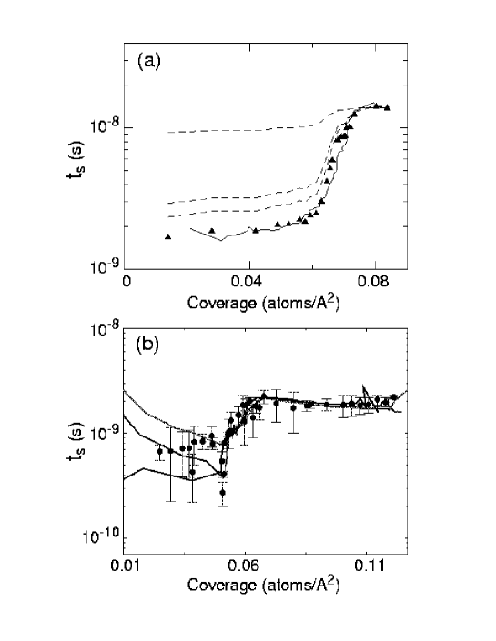
For low coverages, Xe forms solid islands on Ag at T=77.4K. The slip time drops slightly with increasing coverage, presumably due to increasing island size (Tomassone et al., 1997). There is a sharp rise in slip time as the islands merge into a complete monolayer that is gradually compressed with increasing coverage. Fig. 4 shows that the magnitude of the rise in varies from one experiment to the next. The calculated rise is consistent with the larger measured increases.
The simulation results of the two groups can be extended to nonzero values of , using Eq. 12. This would necessarily change the ratio between the slip times of the uncompressed and compressed layers. The situation is illustrated for Kr on Au in Fig. 4(a). The dashed lines were generated by fitting the damping of the compressed monolayer with different ratios of to . As the importance of increases, the change in slip time during compression of the monolayer decreases substantially. The comparison between theory and experiment suggests that is likely to contribute less than 1/3 of the friction in the compressed monolayer, and thus less than 5% in the uncompressed fluid. The measured increase in slip time for Xe on Ag is smaller and the variability noted in Fig. 4b makes it harder to place bounds on . Tomassone et al. (1997) conclude that their results are consistent with no contribution from . When they included a value of suggested by Persson and Nitzan (1996) they still found that phonon friction provided 75% of the total. Persson and Nitzan had concluded that phonons contributed only 2% of the friction in the uncompressed monolayer.
Liebsch et al. (1999) have reached an intermediate conclusion. They compared calculated results for different corrugations to a set of experimental data and chose the corrugation that matched the change in friction with coverage. They conclude that most of the damping at high coverages is due to and most of the damping at low coverages is due to phonons. However, the data they fitted had only a factor of 3 change with increasing coverage and some of the data in Fig. 4b change by a factor of more than 5. Fitting to these sets would decrease their estimate of the size of .
The behavior of commensurate monolayers is very different than that of the incommensurate and fluid layers described so far. As expected from studies of one dimensional models, simulations of commensurate monolayers show that they exhibit static friction. Unfortunately, no experimental results have been obtained because the friction is too high for the QCM technique to measure.
In one of the earliest simulation studies, Persson (1993a) considered a two-dimensional model of Xe on the (100) surface of Ag. Depending on the corrugation strength he found fluid, 2x2 commensurate, and incommensurate phases. He studied as the commensurate phase was approached by lowering temperature in the fluid phase, or decreasing coverage in the incommensurate phase. In both cases he found that went to zero at the boundary of the commensurate phase, implying that there was no flow in response to small forces.
When the static friction is exceeded, the dynamics of adsorbed layers can be extremely complicated. In the model just described, Persson (1993a, 1993b, 1995) found that sliding caused a transition from a commensurate crystal to a new phase. The velocity was zero until the static friction was exceeded. The system then transformed into a sliding fluid layer. Further increases in force caused a first order transition to the incommensurate structure that would be stable in the absence of any corrugation. The velocity in this phase was also what would be calculated for zero corrugation (dashed line). Decreasing the force led to a transition back to the fluid phase at essentially the same point. However, the layer did not return to the initial commensurate phase until the force dropped well below the static friction.
The above hysteresis in the transition between commensurate and fluid states is qualitatively similar to that observed in the underdamped Tomlinson model or the equivalent case of a Josephson junction (McCumber, 1968). As in these cases, the magnitude of the damping effects the range of the hysteresis. The major difference is the origin of the hysteresis. In the Tomlinson model, hysteresis arises solely because the inertia of the moving system allows it to overcome potential barriers that a static system could not. This type of hysteresis would disappear at finite temperature due to thermal excitations (Braun et al., 1997a). In the adsorbed layers, the change in the physical state of the system has also changed the nature of the potential barriers. Similar sliding induced phase transitions were observed earlier in experimental and simulation studies of shear in bulk crystals (Ackerson et al., 1986; Stevens et al., 1991, 1993) and in thin films (Gee et al., 1990; Thompson and Robbins, 1990b). The relation between such transitions and stick-slip motion is discussed in Section VI.
Braun and collaborators have considered the transition from static to sliding states at coverages near to a commensurate value. They studied one (Braun et al., 1997b; Paliy et al., 1997) and two (Braun et al., 1997a, 1997c) dimensional Frenkel-Kontorova models with different degrees of damping. If the corrugation is strong, the equilibrium state consists of locally commensurate regions separated by domain walls or kinks. The kinks are pinned because of the discreteness of the lattice, but this Peierls-Nabarro pinning potential is smaller than the substrate corrugation. In some cases there are different types of kinks with different pinning forces. The static friction corresponds to the force needed to initiate motion of the most weakly pinned kinks. As a kink moves through a region, atoms advance between adjacent local minima in the substrate potential. Thus the average velocity depends on both the kink velocity and the density of kinks. If the damping is strong, there may be a series of sudden transitions as the force increases. These may reflect depinning of more strongly pinned kinks, or creation of new kink-antikink pairs that lead to faster and faster motion. At high enough velocity the kinks become unstable, and a moving kink generates a cascade of new kink-antikink pairs that lead to faster and faster motion. Eventually the layer decouples from the substrate and there are no locally commensurate regions. As in Persson (1995), the high velocity state looks like an equilibrium state with zero corrugation. The reason is that the atoms move over the substrate so quickly that they can not respond. Although this limiting behavior is interesting, it would only occur in experiments between flat crystals at velocities comparable to the speed of sound.
IV Dry Sliding of Crystalline Surfaces
The natural case of interest to tribologists is the sliding interface between two three-dimensional objects. In this section we consider sliding of bare surfaces. We first discuss general issues related to the effect of commensurability, focusing on strongly adhering surfaces such as clean metal surfaces. Then simulations of chemically-passivated surfaces of practical interest are described. The section concludes with studies of friction, wear and indentation in single-asperity contacts.
A Effect of Commensurability
The effect of commensurability in three dimensional systems has been studied by Hirano and Shinjo (1990, 1993). They noted that even two identical surfaces are likely to be incommensurate. As illustrated in Fig. 5, unless the crystalline surfaces are perfectly aligned, the periods will no longer match up. Thus one would expect almost all contacts between surfaces to be incommensurate.

Hirano and Shinjo (1990) calculated the condition for static friction between high symmetry surfaces of fcc and bcc metals. Many of their results are consistent with the conclusions described above for lower dimensions. They first showed that the static friction between incommensurate surfaces vanishes exactly if the solids are perfectly rigid. They then allowed the bottom layer of the top surface to relax in response to the atoms above and below. The relative strength of the interaction between the two surfaces and the stiffness of the top surface plays the same role as in the Tomlinson model. As the interaction becomes stronger, there is an Aubry transition to a finite static friction. This transition point was related to the condition for multi-stability of the least stable atom.
To test whether realistic potentials would be strong enough to produce static friction between incommensurate surfaces, Hirano and Shinjo (1990) applied their theory to noble and transition metals. Contacts between various surface orientations of the same metal (i.e. (111) and (100) or (110) and (111)) were tested. In all cases the interactions were too weak to produce static friction.
Shinjo and Hirano (1993) extended this line of work to dynamical simulations of sliding. They first considered the undamped Frenkel-Kontorova model with ideal springs between atoms. The top surface was given an initial velocity and the evolution of the system was followed. When the corrugation was small, the kinetic friction vanished, and the sliding distance increased linearly with time. This ”superlubric” state disappeared above a threshold corrugation. Sliding stopped because of energy transfer from the center of mass motion into vibrations within the surface. The transition point depended on the initial velocity, since that set the amount of energy that needed to be converted into lattice vibrations. Note that the kinetic friction only vanishes in these simulations because atoms are connected by ideal harmonic springs (Smith et al., 1996). The damping due to energy transfer between internal vibrations (e.g. Eq. 14) is zero because the phonon lifetime is infinite. More realistic anharmonic potentials always lead to an exponential damping of the velocity at long times.
Simulations for two dimensional surfaces were also described (Shinjo and Hirano, 1993; Hirano and Shinjo, 1993). Shinjo and Hirano noted that static friction is less likely in higher dimensions because of the ability of atoms to move around maxima in the substrate potential, as described in Sec. III D. A particularly interesting feature of their results is that the Aubry transition to finite static friction depends on the relative orientation of the surfaces (Hirano and Shinjo, 1993). Over an intermediate range of corrugations, the two surfaces slide freely in some alignments and are pinned in others. This extreme dependence on relative alignment has not been seen in experiments, but strong orientational variations in friction have been seen between mica surfaces (Hirano et al., 1991) and between a crystalline AFM tip and substrate (Hirano et al., 1997).
Hirano and Shinjo’s conclusion that two flat, strongly adhering but incommensurate surfaces are likely to have zero static friction has been supported by two other studies. As described in more detail in Section IV C, Srensen et al. (1996) found that there was no static friction between a sufficiently large copper tip and an incommensurate copper substrate. Müser and Robbins (1999) studied a simple model system and found that interactions within the surfaces needed to be much smaller than the interactions between surfaces in order to get static friction.
Müser and Robbins (1999) considered two identical but orientationally misaligned triangular surfaces similar to Fig. 5C. Interactions within each surface were represented by coupling atoms to ideal lattice sites with a spring constant . Atoms on opposing walls interacted through a Lennard-Jones potential. The walls were pushed together by an external force (MPa) that was an order of magnitude less than the adhesive pressure from the LJ potential. The bottom wall was fixed, and the free diffusion of the top wall was followed at a low temperature (). For , the walls were pinned by static friction for all system sizes investigated. For , vanished, and the top wall diffused freely in the long time limit. By comparison, Lennard-Jones interactions between atoms within the walls would give rise to . Hence, the adhesive interactions between atoms on different surfaces must be an order of magnitude stronger than the cohesive interactions within each surface in order to produce static friction between the flat, incommensurate walls that were considered.
The results described above make it clear that the static friction between ideal crystals can be expected to vanish in many cases. This raises the question of why static friction is observed so universally in experiments. One possibility is that roughness or chemical disorder pins the two surfaces together. Theoretical arguments indicate that disorder will always pin low dimensional objects (e.g. Grüner et al., 1988). However, the same arguments show that the pinning between three-dimensional objects is exponentially weak (Caroli and Nozieres, 1996; Persson and Tosatti, 1996; Volmer and Natterman, 1997). This suggests that other effects like mobile atoms between the surfaces may play a key role in creating static friction. This idea is discussed below in Sec. V C.
B Chemically Passivated Surfaces
The simulations just described aimed at revealing general aspects of friction. There is also a need to understand the tribological properties of specific materials on the nanoscale. Advances in the chemical vapor deposition of diamond hold promise for producing hard protective diamond coatings on a variety of materials. This motivated Harrison et al. (1992b) to perform molecular-dynamics simulations of atomic-scale friction between diamond surfaces.
Two orientationally-aligned, hydrogen-terminated diamond (111) surfaces were placed in sliding contact. Potentials based on the work of Brenner (1990) were used. As discussed in Section VII C, these potentials have the ability to account for chemical reactions, but none occurred in the work described here. The lattices contained ten layers of carbon atoms and two layers of hydrogen atoms, and each layer consisted of 16 atoms. The three outermost layers were treated as rigid units, and were displaced relative to each other at constant sliding velocity and constant separation. The atoms of the next five layers were coupled to a thermostat.
Energy dissipation mechanisms were investigated as a function of load, temperature, sliding velocity, and sliding direction. At low loads, the top wall moved almost rigidly over the potential from the bottom wall, and the average friction was nearly zero. At higher loads, colliding hydrogen atoms on opposing surfaces locked into a metastable state before suddenly slipping past each other. As in the Tomlinson model, energy was dissipated during these rapid pops. The kinetic friction was smaller for sliding along the grooves between nearest neighbor hydrogen terminations, [10], than in the orthogonal direction, [11], because hydrogen atoms on different surfaces could remain farther apart.
In a subsequent study, Harrison et al. (1993) investigated the effect of atomic scale roughness by randomly replacing one eighth of the hydrogen atoms on one surface with methyl, ethyl or n-propyl groups. Changing hydrogen to methyl had little effect on the friction at a given load. However a new type of pop between metastable states was observed: Methyl groups rotated past each other in a rapid turnstile motion. Further increases in the length of the substituted molecules led to much smaller at high loads. These molecules were flexible enough to be pushed into the grooves between hydrogen atoms on the opposing surface, reducing the number of collisions.
Note that Harrison et al. (1992b, 1993) and Perry and Harrison (1996, 1997) might have obtained somewhat different trends using a different ensemble and/or incommensurate walls. Their case of constant separation and velocity corresponds to a system that is much stiffer than even the stiffest AFM. Because they used commensurate walls and constant velocity, the friction depended on the relative displacement of the lattices in the direction normal to the velocity. The constant separation also led to variations in normal load by up to an order of magnitude with time and lateral displacement. To account for these effects, Harrison et al. (1992b, 1993) and Perry and Harrison (1996, 1997) presented values for friction and load that were averaged over both time and lateral displacement. Studies of hydrogen-terminated silicon surfaces (Robbins and Mountain) indicate that changing to a constant load and lateral force ensemble allows atoms to avoid each other more easily. Metastability sets in at higher loads than in a constant separation ensemble, the friction is lower, and variations with sliding direction are reduced.
Glosli and coworkers have investigated the sliding motion between two ordered monolayers of longer alkane chains bound to commensurate walls (McClelland and Glosli, 1992; Glosli and McClelland, 1993; Ohzono et al., 1998). Each chain contained six alkane monomers with fixed bond lengths. Next-nearest neighbors and third-nearest neighbors on the chain interacted via bond bending and torsional potentials, respectively. One end of each chain was harmonically coupled to a site on the triangular lattices that made up each wall. All other interactions were Lennard Jones (LJ) potentials between CH3 and CH2 groups (the united atom model of Sec. II A). The chain density was high enough that chains pointed away from the surface they were anchored to. A constant vertical separation of the walls was maintained, and the sliding velocity was well below the sound velocity. Friction was studied as a function of , , and the ratio of the LJ interaction energies between endgroups on opposing surfaces, , to that within each surface, .
Many results of these simulations correspond to the predictions of the Tomlinson model. Below a threshold value of (0.4 at ), molecules moved smoothly, and the force decreased to zero with velocity. When the interfacial interactions became stronger than this threshold value, “plucking motion” due to rapid pops between metastable states was observed. Glosli and McClelland (1993) showed that at each pluck, mechanical energy was converted to kinetic energy that flowed away from the interface as heat. Ohzono et al. (1998) showed that a generalization of the Tomlinson model could quantitatively describe the sawtooth shape of the shear stress as a function of time. The instantaneous lateral force did not vanish in any of Glosli and McClelland’s (1993) or Ohzono et al.’s (1998) simulations. This shows that there was always a finite static friction, as expected between commensurate surfaces.
For both weak () and strong () interfacial interactions, Glosli and McClelland (1993) observed an interesting maximum in the -dependent friction force. The position of this maximum coincided with the rotational “melting” temperature where orientational order at the interface was lost. It is easy to understand that drops at because thermal activation helps molecules move past each other. The increase in with at low was attributed to increasing anharmonicity that allowed more of the plucking energy to be dissipated.
C Single Asperity Contacts
Engineering surfaces are usually rough, and friction is generated between contacting asperities on the two surfaces. These contacts typically have diameters of order a m or more (e.g. Dieterich and Kilgore, 1996). This is much larger than atomic scales, and the models above may provide insight into the behavior within a representative portion of these contacts. However, it is important to determine how finite contact area and surface roughness effect friction. Studies of atomic-scale asperities can address these issues, and also provide direct models of the small contacts typical of AFM tips.
Srensen et al. performed simulations of sliding tip-surface and surface-surface contacts consisting of copper atoms (Srensen et al., 1996). Flat, clean tips with (111) or (100) surfaces were brought into contact with corresponding crystalline substrates (Fig. 6). The two exterior layers of tip and surface were treated as rigid units, and the dynamics of the remaining mobile layers was followed. Interatomic forces and energies were calculated using semiempirical potentials derived from effective medium theory (Jacobsen et al., 1987). At finite temperatures, the outer mobile layer of both tip and surface was coupled to a Langevin thermostat. Zero temperature simulations gave similar results. To explore the effects of commensurability, results for crystallographically aligned and misoriented tip-surface configurations were compared.

In the commensurate Cu(111) case, Srensen et al. observed atomic-scale stick-slip motion of the tip. The trajectory was of zig-zag form which could be related to jumps of the tip’s surface between fcc and hcp positions. Similar zig-zag motion is seen in shear along (111) planes of bulk fcc solids (Stevens and Robbins, 1993). Detailed analysis of the slips showed that they occurred via a dislocation mechanism. Dislocations were nucleated at the corner of the interface, and then moved rapidly through the contact region. Adhesion led to a large static friction at zero load: The static friction per unit area, or critical yield stress, dropped from 3.0GPa to 2.3GPa as increased from 0 to 300K. The kinetic friction increased linearly with load with a surprisingly small differential friction coefficient . In the load regime investigated, was independent of temperature and load. No velocity dependence was detectable up to sliding velocities of m/s. At higher velocities, the friction decreased. Even though the interactions between the surfaces are identical to those within the surfaces, no wear was observed. This was attributed to the fact that (111) surfaces are the preferred slip planes in fcc metals.
Adhesive wear was observed between a commensurate (100) tip and substrate (Fig. 6). Sliding in the (011) direction at either constant height or constant load led to inter-plane sliding between (111) planes inside the tip. As shown in Fig. 6, this plastic deformation led to wear of the tip, which left a trail of atoms in its wake. The total energy was an increasing function of sliding distance due to the extra surface area. The constant evolution of the tip kept the motion from being periodic, but the saw-toothed variation of force with displacement that is characteristic of atomic-scale stick-slip was still observed.
Nieminen et al. (1992) observed a different mechanism of plastic deformation in essentially the same geometry, but at higher velocities (100m/s vs. 5m/s) and with Morse potentials between Cu atoms. Sliding took place place between (100) layers inside the tip. This led to a reduction of the tip by two layers that was described as the climb of two successive edge dislocations, under the action of the compressive load. Although wear covered more of the surface with material from the tip, the friction remained constant at constant normal load. The reason was that the portion of the surface where the tip advanced had a constant area. While the detailed mechanism of plastic mechanism is very different than in Srensen et al. (1996), the main conclusions of both papers are similar: When two commensurate surfaces with strong adhesive interactions are slid against each other, wear is obtained through formation of dislocations that nucleate at the corners of the moving interface.
Srensen et al. (1996) also examined the effect of incommensurability. An incommensurate Cu(111) system was obtained by rotating the tip by 16.1o about the axis perpendicular to the substrate. For a small tip (5x5 atoms) they observed an Aubry transition from smooth sliding with no static friction at low loads, to atomic-scale stick-slip motion at larger loads. Further increases in load led to sliding within the tip and plastic deformation. Finite systems are never truly incommensurate, and pinning was found to occur at the corners of the contact, suggesting it was a finite-size effect. Larger tips (19x19) slid without static friction at all loads. Similar behavior was observed for incommensurate Cu(100) systems. These results confirm the conclusions of Hirano and Shinjo (1990) that even bare metal surfaces of the same material will not exhibit static friction if the surfaces are incommensurate. They also indicate that contact areas as small as a few hundred atoms are large enough to exhibit this effect.
Many other tip-substrate simulations of bare metallic surfaces have been carried out. Mostly, these simulations concentrated on indentation, rather than on sliding or scraping (see Sec. VII B). Among the indentation studies of metals are simulations of a Ni tip indenting Au(100) (Landman et al., 1990), a Ni tip coated with an epitaxial gold monolayer indenting Au(100) (Landman et al., 1992), an Au tip indenting Ni(001) (Landman and Luedtke, 1989, 1991), an Ir tip indenting a soft Pb substrate (Raffi-Tabar et al., 1992), and an Au tip indenting Pb(110) (Tomagnini et al., 1993). These simulations have been reviewed in detail within this series by Harrison et al. (1999).
In general, plastic deformation occurs mainly in the softer of the two materials, typically Au or Pb in the cases above. Fig. 7 shows the typical evolution of the normal force and potential energy during an indentation at high enough loads to produce plastic deformation (Landman and Luedtke, 1991). As the Au tip approaches the Ni surface (upper line), the force remains nearly zero until a separation of about 1 Å. The force then becomes extremely attractive and there is a jump to contact (A). During the jump to contact, Au atoms in the tip displace by 2 Å within a short time span of 1 ps. This strongly adhesive contact produces reconstruction of the Au layers through the fifth layer of the tip. When the tip is withdrawn, a neck is pulled out of the substrate. The fluctuations in force seen in Fig. 7 correspond to periodic increases in the number of layers of gold atoms in the neck.
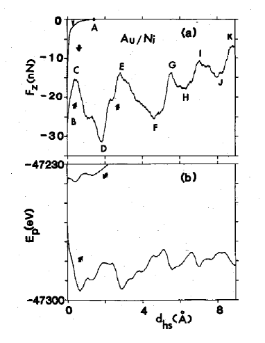
Nanoscale investigations of indentation, adhesion and fracture of non-metallic diamond (111) surfaces have been carried out by Harrison et al. (1992a). A hydrogen-terminated diamond tip was brought in contact with a (111) surface that was either bare or hydrogen-terminated. The tip was constructed by removing atoms from a (111) crystal until it looked like an inverted pyramid with a flattened apex. The model for the surface was similar to that described in Section IV B, but one layer contained 64 atoms. The indentation was performed by moving the rigid layers of the tip in steps of 0.15 Å. The system was then equilibrated before observables were calculated.
Unlike the metal/metal systems (Fig. 7), the diamond/diamond systems (Fig. 8) did not show a pronounced jump to contact (Harrison et al., 1992a). This is because the adhesion between diamond (111) surfaces is quite small if at least one is hydrogen-terminated (Harrison et al., 1991). For effective normal loads up to 200 nN (i.e. small indentations), the diamond tip and surface deformed elastically and the force distance curve was reversible (Fig. 8 (A)). A slight increase to 250nN, led to plastic deformation that produced hysteresis and steps in the force distance curve (Fig. 8 (B)) (Harrison et al., 1992a).
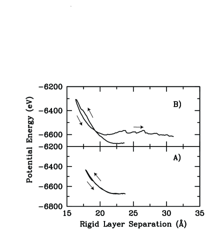
V Lubricated Surfaces
Hydrodynamics and elasto-hydrodynamics have been very successful in describing lubrication by micron-thick films (Dowson and Higginson, 1968). However, these continuum theories begin to break down as atomic structure becomes important. Experiments and simulations reveal a sequence of dramatic changes in the static and dynamic properties of fluid films as their thickness decreases from microns down to molecular scales. These changes have important implications for the function of boundary lubricants. This section describes simulations of these changes, beginning with changes in flow boundary conditions for relatively thick films, and concluding with simulations of submonolayer films and corrugated walls.
A Flow boundary conditions
Hydrodynamic theories of lubrication need to assume a boundary condition (BC) for the fluid velocity at solid surfaces. Macroscopic experiments are generally well-described by a ”no-slip” BC; that is that the tangential component of the fluid velocity equals that of the solid at the surface. The one prominent exception is contact line motion, where an interface between two fluids moves along a solid surface. This motion would require an infinite force in hydrodynamic theory, unless slip occurred near the contact line (Huh and Scriven, 1971; Dussan, 1979).
The experiments on adsorbed monolayers described in Section III E suggest that slip may occur more generally on solid surfaces. As noted, the kinetic friction between the first monolayer and the substrate can be orders of magnitude lower than that between two layers in a fluid. The opposite deviation from no-slip is seen in some Surface Force Apparatus experiments – a layer of fluid molecules becomes immobilized at the solid wall (Chan and Horn, 1985; Israelachvili, 1986).
In pioneering theoretical work, Maxwell (1867) calculated the deviation from a no-slip boundary condition for an ideal gas. He assumed that at each collision molecules were either specularly reflected or exchanged momentum to emerge with a velocity chosen at random from a thermal distribution. The calculated flow velocity at the wall was non-zero, and increased linearly with the velocity gradient near the wall. Taking as the direction normal to the wall and as the tangential component of the velocity relative to the wall, Maxwell found
| (15) |
where is the position of the wall. The constant of proportionality, , has units of length and is called the slip length. It represents the distance into the wall at which the velocity gradient would extrapolate to zero. Calculations with a fictitious wall at this position and no-slip boundary conditions would reproduce the flow in the region far from the wall. also provides a measure of the kinetic friction per unit area between the wall and the adjacent fluid. The shear stress must be uniform in steady state, because any imbalance would lead to accelerations. Since the velocity gradient times the viscosity gives the stress in the fluid, the kinetic friction per unit area is . Maxwell found that increased linearly with the mean free path and that it also increased with the probability of specular reflection.
Early simulations used mathematically flat walls and phenomenological reflection rules like those of Maxwell. For example, Hannon et al. (1988) found that the slip length was reduced to molecular scales in dense fluids. This is expected from Maxwell’s result, since the mean free path becomes comparable to an atomic separation at high densities. However work of this type does not address how the atomic structure of realistic walls is related to collision probabilities and whether Maxwell’s reflection rules are relevant. This issue was first addressed in simulations of moving contact lines where deviations from no-slip boundary conditions have their most dramatic effects (Koplik et al., 1988, 1989; Thompson and Robbins, 1989). These papers found that even when no-slip boundary conditions held for single fluid flow, the large stresses near moving contact lines led to slip within a few molecular diameters of the contact line. They also began to address the relation between the flow boundary condition and structure induced in the fluid by the solid wall.
The most widely studied type of order is layering in planes parallel to the wall. It is induced by the sharp cutoff in fluid density at the wall and the pair correlation function between fluid atoms (Abraham, 1978; Toxvaerd, 1981; Nordholm and Haymet, 1980; Snook and van Megen, 1980; Plischke and Henderson, 1986). An initial fluid layer forms at the preferred wall-fluid spacing. Additional fluid molecules tend to lie in a second layer, at the preferred fluid-fluid spacing. This layer induces a third, and so on.
Some of the trends that are observed in the degree and extent of layering are illustrated in Fig. 9 (Thompson and Robbins, 1990a). The fluid density is plotted as a function of the distance between walls for a model considered in almost all the studies of flow BC’s described below. The fluid consists of spherical molecules interacting with a Lennard-Jones potential. They are confined by crystalline walls containing discrete atoms. In this case the walls were planar (001) surfaces of an fcc crystal. Wall and fluid atoms also interact with a Lennard-Jones potential, but with a different binding energy .
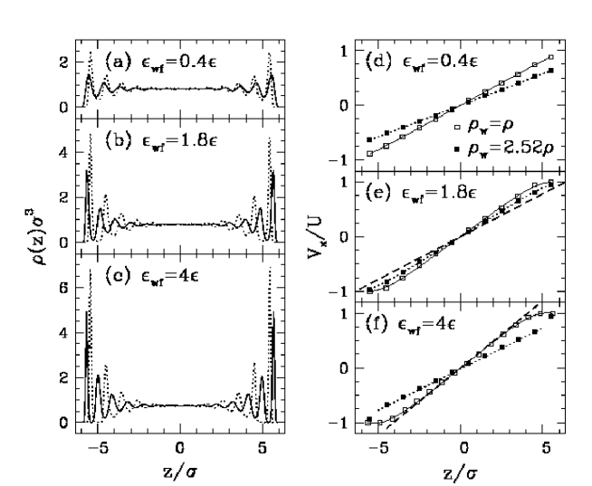
The net adsorption potential from the walls (Eq. 11) can be increased by raising or by increasing the density of the walls so that more wall atoms attract the fluid. Fig. 9 shows that both increases lead to increases in the height of the first density peak. The height also increases with the pressure in the fluid (Koplik et al., 1989; Barrat and Bocquet, 1999a) since that forces atoms into steeper regions of the adsorption potential. The height of subsequent density peaks decreases smoothly with distance from the wall, and only four or five well-defined layers are seen near each wall in Fig. 9. The rate at which the density oscillations decay is determined by the decay length of structure in the bulk pair-correlation function of the fluid. Since all panels of Fig. 9 have the same conditions in the bulk, the decay rate is the same. The adsorption potential only determines the initial height of the peaks.
The pair correlation function usually decays over a few molecular diameters except under special conditions, such as near a critical point. For fluids composed of simple spherical molecules, the oscillations typically extend out to a distance of order 5 molecular diameters (Magda et al., 1985; Schoen et al., 1987; Thompson and Robbins, 1990a). For more complex systems containing fluids with chain or branched polymers, the oscillations are usually negligible beyond 3 molecular diameters (Bitsanis and Hadziianou, 1990; Thompson et al., 1995; Gao et al. 1997a, 1997b). Some simulations with realistic potentials for alkanes show more pronounced layering near the wall because the molecules adopt a rod-like conformation in the first layer (Ribarsky et al., 1992; Xia et al., 1992).
Solid surfaces also induce density modulations within the plane of the layers (Landman et al., 1989; Schoen et al., 1987, 1988, 1989; Thompson and Robbins, 1990a, 1990b). These correspond directly to the modulations induced in adsorbed layers by the corrugation potential (Sec. III E), and can also be quantified by the two-dimensional static structure factor at the shortest reciprocal lattice vector of the substrate. When normalized by the number of atoms in the layer, , this becomes an intensive variable that would correspond to the Debye-Waller factor in a crystal. The maximum possible value, , corresponds to fixing all atoms exactly at crystalline lattice sites. In a strongly ordered case such as in Fig. 9(c), the small oscillations about lattice sites in the first layer only decrease to 0.71. This is well above the value of 0.6 that is typical of bulk 3D solids at their melting point and indicates that the first layer has crystallized onto the wall. This was confirmed by computer simulations of diffusion and flow (Thompson and Robbins, 1990a). The values of in the second and third layers are 0.31 and 0.07, respectively, and atoms in these layers exhibit typical fluid diffusion.
There is some correlation between the factors that produce strong layering and those that produce strong in-plane modulations. For example, chain molecules have several conflicting length scales that tend to frustrate both layering and in-plane order (Thompson et al., 1995; Gao et al., 1997a, 1997b; Koike and Yoneya, 1998, 1999). Both types of order also have a range that is determined by and a magnitude that decreases with decreasing . However, the dependence of in-plane order on the density of substrate atoms is more complicated than for layering. When , the fluid atoms can naturally sit on the sites of a commensurate lattice, and is large. When the substrate density is increased by a factor of 2.52, the fluid atoms no longer fit easily into the corrugation potential. The degree of induced in-plane order drops sharply, although the layering becomes stronger (Fig. 9). Sufficiently strong adsorption potentials may eventually lead to crystalline order in the first layers, and stronger layering. However, this may actually increase slip, as shown below.
Fig. 9 also illustrates the range of flow boundary conditions that have been seen in many studies (Heinbuch and Fischer, 1989; Koplik et al., 1989; Thompson and Robbins, 1990a; Bocquet and Barrat, 1994; Mundy et al., 1996; Khare et al., 1996; Barrat and Bocquet, 1999a). Flow was imposed by displacing the walls in opposite directions along the -axis with speed (Thompson and Robbins, 1990a). The average velocity was calculated within each of the layers defined by peaks in the density (Fig. 9), and normalized by . Away from the walls, all systems exhibit the characteristic Couette flow profile expected for Newtonian fluids. The value of rises linearly with , and the measured shear stress divided by equals the bulk viscosity. Deviations from this behavior occur within the first few layers, in the region where layering and in-plane order are strong. In some cases the fluid velocity remains substantially less than , indicating slip occurs. In others, one or more layers move at the same velocity as the wall, indicating they are stuck to it.
Applying Maxwell’s definition of slip length Eq. 15 to these systems is complicated by uncertainty in where the plane of the solid surface should be defined. The wall is atomically rough, and the fluid velocity can not be evaluated too near to the wall because of the pronounced layering. In addition, the curvature evident in some flow profiles represents a varying local viscosity whose effect must be included the boundary condition.
One approach is to fit the linear flow profile in the central region and extrapolate to the value of where the velocity would reach . The slip length can then be defined as where is the height of the top wall atoms. This is equivalent to applying Maxwell’s definition (Eq. 15) to the extrapolated flow profile at . The no-slip condition corresponds to a flow profile that extrapolates to the wall velocity at as illustrated by the dashed line in Fig. 9(e). Slip produces a smaller velocity gradient and a positive value of . Stuck layers lead to a larger velocity gradient and a negative value of .
The dependence of slip length on many parameters has been studied. All the results are consistent with a decrease in slip as the in-plane order increases. Numerical results for and (Fig. 9(d)) are very close to the no-slip condition. Increasing leads to stuck layers (Koplik et al., 1988, 1989; Thompson and Robbins, 1989, 1990a; Heinbuch and Fischer, 1989), and decreasing can produce large slip lengths (Thompson and Robbins, 1990a; Barrat and Bocquet, 1999a) Increasing pressure (Koplik et al., 1989; Barrat and Bocquet, 1999a) or decreasing temperature (Heinbuch and Fischer, 1989; Thompson and Robbins, 1990a) increases structure in and leads to less slip. These changes could also be attributed to increases in layering. However, increasing the wall density from to 2.52 increases slip in Fig. 9. This correlates with the drop in in-plane order, while the layering actually increases. Changes in in-plane order also explain the pronounced increase in slip when is increased to 4 in the case of dense walls (Fig. 9(f)). The first layer of fluid atoms becomes crystallized with a very different density than the bulk fluid. It becomes the “wall” that produces order in the second layer, and it gives an adsorption potential characterized by rather than . The observed slip is consistent with that for dense walls displaced to the position of the first layer and interacting with .
Thompson and Robbins (1990a) found that all of their results for collapsed on to a universal curve when plotted against the structure factor . When one or more layers crystallized onto the wall, the same collapse could be applied as long as the effective wall position was shifted by a layer and the for the outer wall layer was used. The success of this collapse at small can be understood from the perturbation theory for the kinetic friction on adsorbed monolayers (Eq. 14). The slip length is determined by the friction between the outermost fluid layer and the wall. This depends only on and the phonon lifetime for acoustic waves. The latter changes relatively little over the temperature range considered, and hence is a single-valued function of . The perturbation theory breaks down at large , but the success of the collapse indicates that there is still a one-to-one correspondence between it and the friction.
In a recent paper Barrat and Bocquet (1999b) have derived an expression relating and that is equivalent to Eq. 14. However, in describing their numerical results†††They considered almost the same parameter range as Thompson and Robbins (1990a), but at a lower temperature ( vs. 1.1 or 1.4) and at a single wall density (). they emphasize the correlation between increased slip and decreased wetting (Barrat and Bocquet, 1999a, 1999b). In general the wetting properties of fluids are determined by the adsorption term of the substrate potential (Eq. 11). This correlates well with the degree of layering, but has little to do with in-plane order. In the limit of a perfectly structureless wall one may have complete wetting and yet there is also complete slip. The relation between wetting and slip is very much like that between adhesion and friction. All other things being equal, a greater force of attraction increases the effect of corrugation in the potential and increases the friction. However, there is no one-to-one correspondence between them.
In earlier work Bocquet and Barrat (1993, 1994) provided a less ambiguous resolution to the definition of the slip length than that of Thompson and Robbins (1990a). They noted that the shear rate in the central region of Couette flow depended only on the sum of the wall position and the slip length. Thus one must make a somewhat arbitrary choice of wall position to fix the slip length. However, if one also fits the flow profile for Poiseuille flow, unique values of slip length and the effective distance between the walls are obtained (Barrat and Bocquet, 1999a). Bocquet and Barrat (1993, 1994) also suggested and implemented an elegant approach for determining both and using equilibrium simulations and the fluctuation-dissipation theorem. This is one of the first applications of the fluctuation-dissipation theorem to boundary conditions. It opens up the possibility of calculating flow boundary conditions directly from equilibrium thermodynamics, and Bocquet and Barrat (1994) were able to derive Kubo relations for and . Analytic results for these relations are not possible in general, but in the limit of weak interactions they give an expression equivalent to Eq. 14 for the drag on the wall as noted above (Barrat and Bocquet, 1999b). Mundy et al. (1996) have proposed a non-equilibrium simulation method for calculating these quantities directly.
In all of the work described above, care was taken to ensure that the slip boundary condition was independent of the wall velocity. Thus both the bulk of the fluid and the interfacial region were in the linear response regime where the fluctuation-dissipation theorem holds. This linear regime usually extends to very high shear rates ( for spherical molecules). However, Thompson and Troian (1997) found that under some conditions the interfacial region exhibits nonlinear behavior at much lower shear rates than the bulk fluid. They also found a universal form for the deviation from a linear stress/strain-rate relationship at the interface. The fundamental origin for this non-linearity is that there is a maximum stress that the substrate can apply to the fluid. This stress roughly corresponds to the maximum of the force from the corrugation potential times the areal density of fluid atoms. The stress/velocity relation at the interface starts out linearly and then flattens as the maximum stress is approached. The shear rate in the fluid saturates at the value corresponding to the maximum shear stress and the amount of slip at the wall grows arbitrarily large with increasing wall velocity. Similar behavior was observed for more realistic potentials by Koike and Yoneya (1998, 1999).
B Phase Transitions and Viscosity Changes in Molecularly Thin Films
One of the surprising features of Fig. 9 is that the viscosity remains the same even in regions near the wall where there is pronounced layering. Any change in viscosity would produce a change in the velocity gradient since the stress is constant. However, the flow profiles in panel (d) remain linear throughout the cell. The profile for the dense walls in panel (f) is linear up to the last layer, which has crystallized onto the wall. From Fig. 9 it is apparent that density variations by at least a factor of seven can be accommodated without a viscosity change.
The interplay between layering and viscosity was studied in detail by Bitsanis et al. (1987), although their use of artificial flow reservoirs kept them from addressing flow BC’s. They were able to fit detailed flow profiles using only the bulk viscosity evaluated at the average local density. This average was taken over a distance of order that smeared out the rapid density modulations associated with layering, but not slower variations due to the adsorption potential of the walls or an applied external potential.
In subsequent work, Bitsanis et al. (1990) examined the change in viscosity with film thickness. They found that results for films thicknesses could be fit using the bulk viscosity for the average density. However, as decreased below , the viscosity diverged much more rapidly than any model based on bulk viscosity could explain.
These observations were consistent with experiments on nanometer thick films of a wide variety of small molecules. These experiments used the Surface Force Apparatus (SFA) which measures film thickness with Å resolution using optical interferometry. Films were confined between atomically flat mica sheets at a fixed normal load, and sheared with a steady (Gee et al., 1990) or oscillating (Granick, 1992) velocity. Layering in molecularly thin films gave rise to oscillations in the energy, normal force and effective viscosity (Horn and Israelachvili, 1981; Israelachvili, 1991; Georges et al., 1993) as the film thickness decreased. The period of these oscillations was a characteristic molecular diameter. As the film thickness decreased below 7 to 10 molecular diameters, the effective viscosity increased dramatically (Gee et al., 1990; Granick, 1992; Klein and Kumacheva, 1995). Most films of one to three molecular layers exhibited a yield stress characteristic of solid-like behavior, even though the molecules form a simple Newtonian fluid in the bulk.
Pioneering grand canonical Monte Carlo simulations by Schoen et al. (1987) showed crystallization of spherical molecules between commensurate walls separated by up to 6 molecular diameters. However, the crystal was only stable when the thickness was near to an integral number of crystalline layers. At intermediate , the film transformed to a fluid state. Later work (Schoen et al., 1988, 1989), showed that translating the walls could also destabilize the crystalline phase and lead to periodic melting and freezing transitions as a function of displacement. However, these simulations were carried out at equilibrium and did not directly address the observed changes in viscosity.
SFA experiments can not determine the flow profile within the film, and this introduces ambiguity in the meaning of the viscosity values that are reported. Results are typically expressed as an effective viscosity where is the measured shear stress and represents the effective shear rate that would be present if the no-slip condition held and walls were displaced at relative velocity . Deviations from the no-slip condition might cause to differ from the bulk viscosity by an order of magnitude. However, they could not explain the observed changes of by more than five orders of magnitude or the even more dramatic changes by 10 to 12 orders of magnitude in the characteristic viscoelastic relaxation time determined from the shear rate dependence of (Gee et al., 1990; Hu et al., 1991).
Thompson et al. (1992) found very similar changes in viscosity and relaxation time in simulations of a simple bead-spring model of linear molecules (Kremer and Grest, 1990). Some of their results for the effective viscosity vs. effective shear rate are shown in Fig. 10. In (a), the normal pressure was fixed and the number of atomic layers, , was decreased from 8 to 2. In (b), the film was confined by increasing the pressure at fixed particle number. Both methods of increasing confinement lead to dramatic changes in the viscosity and relaxation time.
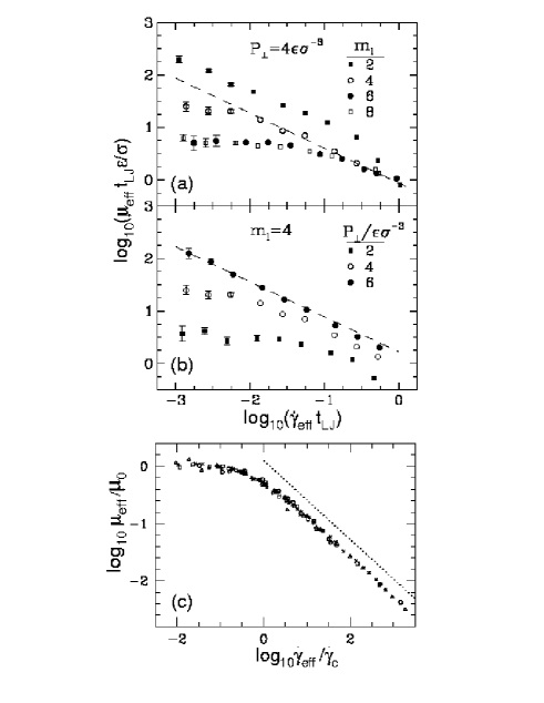
The shear rate dependence of in Fig. 10 has the same form as in experiment (Hu et al., 1991). A Newtonian regime with constant viscosity is seen at the lowest shear rates in all but the uppermost curve in each panel. Above a characteristic shear rate the viscosity begins to decrease rapidly. This shear thinning is typical of viscoelastic media and indicates that molecular rearrangements are too slow to respond to the sliding walls at . As a result, the structure of the fluid begins to change in a way that facilitates shear. A characteristic time for molecular rearrangements in the film can be associated with . Increasing confinement by decreasing or increasing pressure, increases the Newtonian viscosity and relaxation time. For the uppermost curve in each panel, the relaxation time is longer than the longest simulation runs ( time steps) and the viscosity continues to increase at the lowest accessible shear rates. Note that the ranges of shear rate covered in experiment and simulations differ by orders of magnitude. However, the scaling discussed below suggests that the same behavior may be operating in both.
For the parameters used in Fig. 10, studies of the flow profile in four layer films showed that one layer of molecules was stuck to each wall and shear occurred in the middle layers. Other parameter sets produced varying degrees of slip at the wall/film interface, yet the viscoelastic response curves showed the same behavior. Later work by Baljon and Robbins (1996, 1997) shows that lowering the temperature through the bulk glass transition also produces similar changes in viscoelastic response. This suggests that the same glass transition is being produced by changes in thickness, pressure or temperature.
Following the analogy to bulk glass transitions, Thompson et al. (1993, 1995) have shown that changes in equilibrium diffusion constant and can be fit to a free volume theory. Both vanish as where is the film thickness at the glass transition. Moreover, at , they found behavior characteristic of a solid. Films showed a yield stress and no measurable diffusion. When forced to slide, shear localized at the wall/film interface and dropped as , implying that the shear stress is independent of sliding velocity. This is just the usual form of kinetic friction between solids.
The close relation between bulk glass transitions and those induced by confinement can perhaps best be illustrated by using a generalization of time-temperature scaling. In bulk systems it is often possible to collapse the viscoelastic response onto a universal curve by dividing the viscosity by the Newtonian value, , and dividing the shear rate by the characteristic rate, . Demirel and Granick (1996a) found that this approach could be used to collapse data for the real and imaginary parts of the elastic moduli of confined films at different thicknesses. Fig. 10(c) shows that simulation results for the viscosity of thin films can also be collapsed using Demirel and Granick’s approach (Robbins and Baljon, 2000). Data for different thicknesses, normal pressures, and interaction parameters taken from all parameters considered by Thompson et al. (1992, 1995) collapse onto a universal curve. Also shown on the plot (circles) are data for different temperatures that were obtained for longer chains in films that are thick enough to exhibit bulk behavior (Baljon and Robbins, 1996, 1997). The data fit well on to the same curve, providing a strong indication that a similar glass transition occurs whether thickness, normal pressure, or temperature is varied.
The high shear rate region of the universal curve shown in Fig. 10(c) exhibits power law shear thinning: with a best fit exponent . In SFA experiments, Hu et al. (1991) found shear thinning of many molecules was consistent with near -2/3. However, the response of some fluids followed power laws closer to -.5 as they became less confined (Carson et al., 1992). One possible explanation for this is that these measurements fall onto the crossover region of a universal curve like Fig. 10(c). The apparent exponent obtained from the slope of this log-log plot varies from 0 to -2/3 as drops from to about . Many of the experiments that found smaller exponents were only able to observe a drop in by an order of magnitude. As confinement was increased, and a larger drop in viscosity was observed, the slope increased toward -2/3. It would be interesting to attempt a collapse of experimental data on a curve like Fig. 10(c) to test this hypothesis.
Another possibility is that the shear thinning exponent depends on some detail of the molecular structure. Chain length alone does not appear to affect the exponent, since results for chains of length and are combined in Fig. 10(c). Manias et al. (1996) find that changing the geometry from linear to branched has little effect on shear thinning. In most simulations of simple spherical molecules, crystallization occurs before the viscosity can rise substantially above the bulk value. However, Hu et al. (1996) have found a set of conditions where spherical molecules follow a slope over two-decades in shear rate.
Stevens et al. (1997) have performed simulations of confined films of hexadecane using a detailed model of the molecular structure and interactions. They found that films crystallized before the viscosity rose much above bulk values. This prevented them from seeing large power law scaling regimes, but the apparent exponents were consistently less than those for bead spring models. It is not clear whether the origin of this discrepancy is the inability to approach the glass transition, or whether structural changes under shear lead to different behavior. Hexadecane molecules have some tendency to adopt a linear configuration and become aligned with the flow. This effect is not present in simpler bead-spring models.
Shear thinning typically reflects changes in structure that facilitate shear. Experiments and the above simulations were done at constant normal load. In bead-spring models the dominant structural change is a dilation of the film that creates more room for molecules to slide past each other. The dilations are relatively small, but have been detected in some experiments (Dhinojwala and Granick). When simulations are done at constant wall spacing, the shear-thinning exponent drops to (Thompson et al., 1992, 1995; Manias et al., 1996). Kröger et al. (1993) find the same exponent in bulk simulations of these molecules at constant volume, indicating that a universal curve like that in Fig. 10(c) might also be constructed for constant volume instead of constant pressure.
Several analytic models have been developed to explain the power law behavior observed in experiment and simulations. All the models find an exponent of -2/3 in certain limits. However, they start from very different sets of assumptions and it is not clear if any of these correspond to the simulations and experiments. Two of the models yield an exponent of -2/3 for constant film thickness (Rabin and Hersht, 1993; Urbakh et al., 1995) where simulations give . Urbakh et al. (1995) also find that the exponent depends on the velocity profile, while simulations do not. The final model (deGennes) is based on scaling results for the stretching of polymers under shear. While it may be appropriate for thick films, it can not describe the behavior of films which exhibit plug-like flow. It remains to be seen if the -2/3 exponent has a single explanation or arises from different mechanisms in different limits.
The results described in this section have interesting implications for the function of macroscopic bearings. Some bearings may operate in the boundary lubrication regime where the separation between asperities decreases to molecular dimensions. The dramatic increase in viscosity due to confinement may play a key role in preventing squeeze-out of the lubricant and direct contact between asperities. Although the glassy lubricant layer would not have a low frictional force, the yield stress would be lower than that for asperities in contact. More importantly, the amount of wear would be greatly reduced by the glassy film. Studies of confined films may help to determine what factors control a lubricant’s ability to form a robust protective layer at atomic scales. As we now discuss, they may also help explain the pervasive observation of static friction.
C Submonolayer Lubrication
Physisorbed molecules, such as the short hydrocarbon chains considered above, can be expected to sit on any surface exposed to atmospheric conditions. Even in ultra-high-vacuum, special surface treatments are needed to remove strongly physisorbed species from surfaces. Recent work shows that the presence of these physisorbed molecules qualitatively alters the tribological behavior between two incommensurate walls (He et al., 1999; Müser and Robbins, 1999) or between two disordered walls (Müser and Robbins)
As noted in Sec. IV, the static friction is expected to vanish between most incommensurate surfaces. Under similar conditions, the static friction between most amorphous, but flat, interfaces vanishes in the thermodynamic limit (Müser and Robbins). In both cases, the reason is that the density modulations on two bare surfaces can not lock into phase with each other unless the surfaces are unrealistically compliant. However, a sub-monolayer of molecules that form no strong covalent bonds with the walls can simultaneously lock to the density modulations of both walls. This gives rise to a finite static friction for all surface symmetries: commensurate, incommensurate, and amorphous (Müser and Robbins).
A series of simulations were performed in order to elucidate the influence of such ”between-sorbed” particles on tribological properties (He et al., 1999; Müser and Robbins, 1999). A layer of spherical or short “bead-spring” (Kremer and Grest, 1990) molecules was confined between two fcc (111) surfaces. The walls had the orientations and lattice spacings shown in Fig. 5, and results are labeled by the letters in this figure. Wall atoms were bound to their lattice sites with harmonic springs as in the Tomlinson model. The interactions between atoms on opposing walls, as well as fluid-fluid and fluid-wall interactions, had the LJ form. Unless noted, the potential parameters for all three interactions were the same.
The static friction per unit contact area, or yield stress , was determined from the lateral force needed to initiate steady sliding of the surfaces at fixed pressure. When there were no molecules between the surfaces, there was no static friction unless the surfaces were commensurate. As illustrated in Fig. 11(a), introducing a thin film led to static friction in all cases. Moreover, all incommensurate ‡‡‡Although perfectly incommensurate walls are not consistent with periodic boundary conditions, the effect of residual commensurability was shown to be negligible (Muser and Robbins, 1999). cases (B-D) showed nearly the same static friction, and was independent of the direction of sliding relative to crystalline axes (e.g. along or for case D).
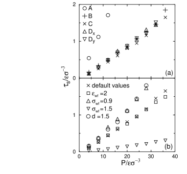
Most experiments do not control the crystallographic orientation of the walls relative to each other or to the sliding direction, yet the friction is fairly reproducible. This is hard to understand based on models of bare surfaces which show dramatic variations in friction with orientation (Hirano and Shinjo, 1993; Srensen et al., 1996; Robbins and Smith, 1996). Fig. 11 shows that a thin layer of molecules eliminates most of this variation. In addition, the friction is insensitive to chain length, coverage, and other variables that are not well controlled in experiments (He et al., 1999). The kinetic friction is typically about 10 to 20% lower than the static friction in all cases (He and Robbins).
Of course experiments do observe changes in friction with surface material. The main factor that changed in this simple model was the ratio of the characteristic length for wall-fluid interactions to the nearest-neighbor spacing on the walls, . As shown in Fig. 11(b), increasing decreases the friction. The reason is that larger fluid atoms are less able to penetrate between wall atoms and thus feel less surface corrugation. Using amorphous, but flat, walls also produced a somewhat larger static friction.
Note that rises linearly with the imposed pressure in all cases shown in Fig. 11. This provides a microscopic basis for the phenomenological explanation of Amontons’ laws that was proposed by Bowden and Tabor (1986). The total static friction is given by the integral of the yield stress over areas of the surface that are in molecular contact. If , then the total force is where is the load and is the total contact area. The coefficient of friction is then where is the mean contact pressure. Amontons’ laws say that is independent of load and the apparent area of the surfaces in contact. This condition is satisfied if is small or if is constant. The latter condition is expected to hold for both ideal elastic (Greenwood and Williamson, 1966) and plastic (Bowden and Tabor, 1986) surfaces.
The above results suggest that adsorbed molecules and other “third-bodies” may prove key to understanding macroscopic friction measurements. It will be interesting to extend these studies to more realistic molecular potentials and to rough surfaces. To date, realistic potentials have only been used between commensurate surfaces, and we now describe some of this work.
The effect of small molecules injected between two sliding hydrogen-terminated (111) diamond surfaces on kinetic friction was investigated by Perry and Harrison (1996, 1997). The setup of the simulation was similar to the one described in Section IV B. Two sets of simulations were performed. In one set, bare surfaces were considered. In another set, either two methane (CH4) molecules, one ethane (C2H6) molecule, or one isobutane (CH3)3CH molecule was introduced into the interface between the sliding diamond surfaces. Experiments show that the friction between diamond surfaces goes down as similar molecules are formed in the contact due to wear (Hayward, 1991).
Perry and Harrison found that these third bodies also reduced the calculated frictional force between commensurate diamond surfaces. The reduction of the frictional force with respect to the bare hydrogen-terminated case was most pronounced for the smallest molecule, methane. The molecular motions were analyzed in detail to determine how dissipation occurred. Methane produced less friction because it was small enough to roll in grooves between the terminal hydrogen atoms without collisions. The larger ethane and isobutane collided frequently.
As for the simple bead-spring model described above, the friction increased roughly linearly with load. Indeed, Perry and Harrison’s data for all third bodies corresponds to , which is close to that for commensurate surfaces in Fig. 11(a). One may expect that the friction would decrease if incommensurate walls were used. However, the rolling motion of methane might be prevented in such geometries.
Perry and Harrison (1996, 1997) compared their results to earlier simulations (Harrison et al., 1993) where hydrogen terminations on one of the two surfaces were replaced by chemisorbed methyl (-CH3), ethyl (-C2H5), or -propyl (-C3H7) groups (Sec. IV B). The chemisorbed molecules were seen to give a considerably smaller reduction of the friction with respect to the physisorbed molecules. Perry and Harrison note that the chemisorbed molecules have fewer degrees of freedom, and so are less able to avoid collisions that dissipate energy.
D Corrugated Surfaces
The presence of roughness can be expected to alter the behavior of lubricants, particularly when the mean film thickness is comparable to the surface roughness. Gao et al. (1995, 1996) and Landman et al. (1996) used molecular dynamics to investigate this thin film limit. Hexadecane (-C16H34) was confined between two gold substrates exposing only (111) surfaces (Fig. 12). The two outer layers of the substrates were completely rigid and were displaced laterally with a constant relative velocity of 10 to 20m/s at constant separation. The asperities on both walls were modeled by flat-topped pyramidal ridges with initial heights of 4 to 6 atomic layers. The united atom model (Sec. II A) was used for the interactions within the film, and the embedded atom method for Au-Au interactions. All other interactions were modeled with suitable 6-12 Lennard-Jones potentials. The alkane molecules and the gold atoms in the asperities were treated dynamically using the Verlet algorithm. The temperature was kept constant at K by rescaling the velocities every fiftieth time step.

Simulations were done in three different regimes, which can be categorized according to the separation that the outer surfaces of the asperities would have if they were placed on top of one another without deforming elasticly or plasticly. The cases were (1) large separation of the asperities Å, (2) a near-overlap regime with Å, and (3) an asperity-overlap regime with Å. Some selected atomic and molecular configurations obtained in a slice through the near-overlap system are shown in Fig. 12. In all cases, the initial separation of the walls was chosen such that the normal pressure was zero for large lateral asperity separations.
One common feature of all simulations was the formation of lubricant layers between the asperities as they approached each other (Fig. 12). This is just like the layering observed in equilibrium between flat walls (e.g. Fig. 9), but the layers form dynamically. The number of layers decreased with decreasing lateral separation between the asperities, and the lateral force showed strong oscillations as successive layers were pushed out. This behavior is shown in Fig. 13 for the near-overlap case.

For large separation, case (1), four lubricant layers remained at the point of closest approach between the asperities, and no plastic deformation occurred. In case (2), severe plastic deformation occurred after local shear and normal stresses exceeded a limiting value of close to 4 GPa. This deformation led to direct intermetallic junctions, which were absent in simulations under identical conditions but with no lubricant molecules in the interface. The junctions eventually broke upon continued sliding, resulting in transfer of some metal atoms between the asperities. As in the overlap case (3), great densification and pressurization of the lubricant in the asperity region occurred, accompanied by a significant increase in the effective viscosity in that region. For the near-overlap system, local rupture of the film in the region between the departing asperities was seen. A nanoscale cavitated zone of length scale Å was observed that persisted for about 100 ps. The Deborah number was studied as well. can be defined as the ratio of the relaxation time of the fluid to the time of passage of the fluid through a characteristic distance . was observed for the near-overlap system, which corresponds to a viscoelastic response of the lubricant. The increased confinement in the overlap system, resulted in , which can be associated with highly viscoelastic behavior, perhaps even elasto-plastic or waxy behavior.
Gao et al. (1996) observed extreme pressures of 150 GPa in the near-overlap case when the asperities were treated as rigid units. Allowing only the asperities to deform reduces the peak pressure by almost two orders of magnitude. However, even these residual pressures are still quite large, and one may expect that a full treatment of the elastic response of the substrates might lead to further dramatic decreases in pressure and damage. Tutein et al. (2000) have recently compared friction between monolayers of anchored hydrocarbon molecules and rigid or flexible nanotubes. Studies of elasticity effects in larger asperities confining films that are several molecules thick are currently in progress (Persson and Ballone).
VI Stick-Slip Dynamics
The dynamics of sliding systems can be very complex and depend on many factors, including the types of metastable states in the system, the times needed to transform between states, and the mechanical properties of the device that imposes the stress. At high rates or stresses, systems usually slide smoothly. At low rates the motion often becomes intermittent, with the system alternately sticking and slipping forward (Rabinowicz, 1965; Bowden and Tabor, 1986). Everyday examples of such stick-slip motion include the squeak of hinges and the music of violins.
The alternation between stuck and sliding states of the system reflects changes in the way energy is stored. While the system is stuck, elastic energy is pumped into the system by the driving device. When the system slips, this elastic energy is released into kinetic energy, and eventually dissipated as heat. The system then sticks once more, begins to store elastic energy, and the process continues. Both elastic and kinetic energy can be stored in all the mechanical elements that drive the system. The whole coupled assembly must be included in any analysis of the dynamics.
The simplest type of intermittent motion is the atomic-scale stick-slip that occurs in the multistable regime () of the Tomlinson model (Fig. 2(b)). Energy is stored in the springs while atoms are trapped in a metastable state, and converted to kinetic energy as they pop to the next metastable state. This phenomenon is quite general and has been observed in several of the simulations of wearless friction described in Sec. IV as well as in the motion of atomic force microscope tips (e.g. Carpick and Salmeron, 1997). In these cases, motion involves a simple ratcheting over the surface potential through a regular series of hops between neighboring metastable states. The slip distance is determined entirely by the periodicity of the surface potential. Confined films and adsorbed layers have a much richer potential energy landscape due to their many internal degrees of freedom. One consequence is that stick-slip motion between neighboring metastable states can involve microslips by distances much less than a lattice constant (Thompson and Robbins, 1990b; Baljon and Robbins, 1997; Robbins and Baljon, 2000). An example is seen at in Fig. 14(b). Such microslips involve atomic-scale rearrangements within a small fraction of the system. Closely related microslips have been studied in granular media (Nasuno et al., 1997; Veje et al., 1999) and foams (Gopal and Durian, 1995).
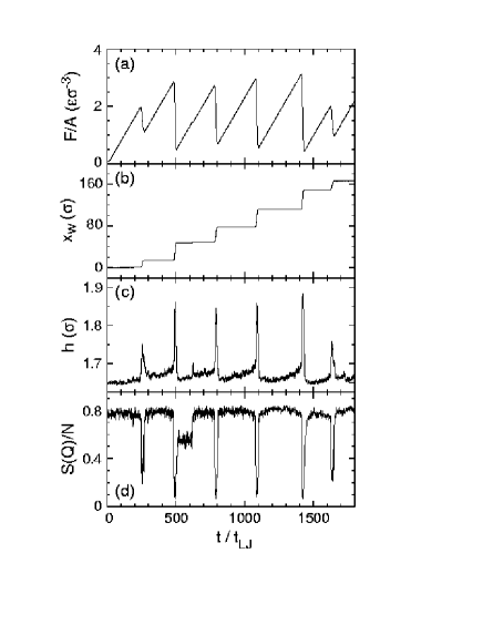
Many examples of stick-slip involve a rather different type of motion that can lead to intermittency and chaos (Ruina, 1983; Heslot et al., 1994). Instead of jumping between neighboring metastable states, the system slips for very long distances before sticking. For example, Gee et al. (1990) and Yoshizawa et al. (1993) observed slip distances of many microns in their studies of confined films. This distance is much larger than any characteristic periodicity in the potential, and varied with velocity, load, and the mass and stiffness of the SFA. The fact that the SFA does not stick after moving by a lattice constant indicates that sliding has changed the state of the system in some manner, so that it can continue sliding even at forces less than the yield stress. Phenomenological theories of stick-slip often introduce an unspecified ”state” variable to model the evolving properties of the system (Dieterich, 1979; Ruina, 1983; Batista and Carlson, 1998).
One simple property that depends on past history is the amount of stored kinetic energy. This can provide enough inertia to carry a system over potential energy barriers even when the stress is below the yield stress. Inertia is readily included in the Tomlinson model and has been thoroughly studied in the mathematically equivalent case of an underdamped Josephson junction (McCumber, 1968). One finds a hysteretic response function where static and moving steady-states coexist over a range of forces between and the static friction . There is a minimum stable steady-state velocity corresponding to . At lower velocities, the only steady state is linearly unstable because – pulling harder slows the system. It is well-established that this type of instability can lead to stick-slip motion (Bowden and Tabor, 1986; Rabinowicz, 1965). If the top wall of the Tomlinson model is pulled at an average velocity less than by a sufficiently compliant system, it will exhibit large-scale stick-slip motion.
Confined films have structural degrees of freedom that can change during sliding, and this provides an alternative mechanism for stick-slip motion (Thompson and Robbins, 1990b). Some of these structural changes are illustrated in Fig. 14 which shows stick-slip motion of a two layer film of simple spherical molecules. The bounding walls were held together by a constant normal load. A lateral force was applied to the top wall through a spring attached to a stage that moved with fixed velocity in the direction. The equilibrium configuration of the film at is a commensurate crystal that resists shear. Thus at small times, the top wall remains pinned at . The force grows linearly with time, , as the stage advances ahead of the wall. When exceeds , the wall slips forward. The force drops rapidly because the slip velocity is much greater than . When the force drops sufficiently, the film recrystallizes, the wall stops, and the force begins to rise once more.
One structural change that occurs during each slip event is dilation by about 10% (Fig. 14(c)). Dhinojwala and Granick have recently confirmed that dilation occurs during slip in SFA experiments. The increased volume makes it easier for atoms to slide past each other and is part of the reason that the sliding friction is lower than . The system may be able to keep sliding in this dilated state as long as it takes more time for the volume to contract than for the wall to advance by a lattice constant. Dilation of this type plays a crucial role in the yield, flow and stick-slip dynamics of granular media (Thompson and Grest, 1991; Jaeger et al., 1996; Nasuno et al., 1997).
The degree of crystallinity also changes during sliding. As in Secs. III E and V A, deviations from an ideal crystalline structure can be quantified by the Debye-Waller factor (Fig. 14d), where is one of the shortest reciprocal lattice vectors and is the total number of atoms in the film. When the system is stuck, has a large value that is characteristic of a 3D crystal. During each slip event, drops dramatically. The minimum values are characteristic of simple fluids that would show a no-slip boundary condition (Sec. V A). The atoms also exhibit rapid diffusion that is characteristic of a fluid. The periodic melting and freezing transitions that occur during stick-slip are induced by shear and not by the negligible changes in temperature. Shear-melting transitions at constant temperature have been observed in both theoretical and experimental studies of bulk colloidal systems (Ackerson et al., 1986; Stevens and Robbins, 1993). While the above simulations of confined films used a fixed number of particles, Lupowski and van Swol (1991) found equivalent results at fixed chemical potential.
Very similar behavior has been observed in simulations of sand (Thompson and Grest, 1991), chain molecules (Robbins and Baljon, 2000), and incommensurate or amorphous walls (Thompson and Robbins, 1990b). These systems transform between glassy and fluid states during stick-slip motion. As in equilibrium, the structural differences between glass and fluid states are small. However, there are strong changes in the self-diffusion and other dynamic properties when the film goes from the static glassy to sliding fluid state.
In the cases just described, the entire film transforms to a new state, and shear occurs throughout the film. Another type of behavior is also observed. In some systems shear is confined to a single plane - either a wall/film interface, or a plane within the film (Baljon and Robbins, 1997; Robbins and Baljon, 2000). There is always some dilation at the shear plane to facilitate sliding. In some cases there is also in-plane ordering of the film to enable it to slide more easily over the wall. This ordering remains after sliding stops, and provides a mechanism for the long-term memory seen in some experiments (Gee et al., 1990; Yoshizawa et al., 1993; Demirel and Granick, 1996b). Buldum and Ciraci (1997) found stick-slip motion due to periodic structural transformations in the bottom layers of a pyramidal Ni(111) tip sliding on an incommensurate Cu(110) surface.
The dynamics of the transitions between stuck and sliding states are crucial in determining the range of velocities where stick-slip motion is observed, the shape of the stick-slip events, and whether stick-slip disappears in a continuous or discontinuous manner. Current models are limited to energy balance arguments (Robbins and Thompson, 1991; Thompson and Robbins, 1993) or phenomenological models of the nucleation and growth of ”frozen” regions (Yoshizawa et al., 1993; Heslot et al., 1994; Batista and Carlson, 1998; Persson, 1998). Microscopic models and detailed experimental data on the sticking and unsticking process are still lacking.
Rozman et al. (1996, 1997, 1998) have taken an interesting approach to unraveling this problem. They have performed detailed studies of stick-slip in a simple model of a single incommensurate chain between two walls. This model reproduces much of the complex dynamics seen in experiments and helps to elucidate what can be learned about the nature of structural changes within a contact using only the measured macroscopic dynamics.
VII Strongly Irreversible Tribological Processes
Sliding at high pressures, high rates, or for long times can produce more dramatic changes in the structure and even chemistry of the sliding interface than those discussed so far. In this concluding chapter, we describe some of the more strongly irreversible tribological processes that have been studied with simulations. These include grain boundary formation and mixing, machining and tribochemical reactions.
A Plastic Deformation
For ductile materials, plastic deformation is likely to occur throughout a region of some characteristic width about the nominal sliding interface (Rigney and Hammerberg, 1998). Sliding induced mixing of material from the two surfaces and sliding induced grain boundaries are two of the experimentally observed processes that lack microscopic theoretical explanations. In an attempt to get insight into the microscopic dynamics of these phenomena, Hammerberg et al. (1998) performed large-scale simulations of a two-dimensional model for copper. The simulation cell contained Cu atoms that were subject to a constant normal pressure . Two reservoir regions at the upper and lower boundaries of the cell were constrained to move at opposite lateral velocities . The initial interface was midway between the two reservoirs.
The friction was measured at GPa as a function of the relative sliding velocity . Different behavior was seen at velocities above and below about 10% of the speed of transverse sound. At low velocities, the interface welded together and the system formed a single workhardened object. Sliding took place at the artificial boundary with one of the reservoirs. At higher velocities the friction was smaller, and decreased steadily with increasing velocity. In this regime, intense plastic deformation occurred at the interface. Hammerberg et al. (1998) found that the early time-dynamics of the interfacial structure could be reproduced with a Frenkel-Kontorova model. As time increased, the interface was unstable to the formation of a fine-grained polycrystalline microstructure, which coarsened with distance away from the interface as a function of time. Associated with this microstructure was the mixing of material across the interface.

B Wear
Large scale, two and three-dimensional molecular dynamics simulations of the indentation and scraping of metal surfaces were carried out by Belak and Stowers (1992). Their simulations show that tribological properties are strongly affected by wear or the generation of debris. A blunted carbon tip was first indented into a copper surface and then pulled over the surface. The tip was treated as a rigid unit. Interactions within the metal were modeled with an embedded atom potential and Lennard-Jones potentials were used between Si and Cu atoms.
In the two-dimensional simulation, indentation was performed at a constant velocity of about 1 m/s. The contact followed Hertzian behavior up to a load nN and an indentation of about 3.5 Cu layers. The surface then yielded on one side of the tip, through the creation of a single dislocation edge on one of the easy slip planes. The load needed to continue indenting decreased slightly until an indentation of about five layers. Then the load began to rise again as stress built up on the side that had not yet yielded. After an indentation of about six layers, this side yielded, and further indentation could be achieved without a considerable increase in load. The hardness, defined as the ratio of load to contact length (area), slightly decreased with increasing load once plastic deformation had occurred.
After indentation was completed, the carbon tip was slid parallel to the original Cu surface. The work to scrape off material was determined as a function of the tip radius. A power law dependence was found at small tip radii that did not correspond to experimental findings for micro-scraping. However, at large tip radii, the power law approached the experimental value. Belak and Stowers found that this change in power law was due to a change in the mechanism of plastic deformation from intragranular to intergranular plastic deformation.
In the three-dimensional (3D) simulations, the substrate contained as many as 36 layers or 72,576 atoms. Hence long-range elastic deformations were included. The surface yielded plastically after an indentation of only 1.5 layers, through the creation of a small dislocation loop. The accompanying release of load was much bigger than in 2D. Further indentation to about 6.5 layers produced several of these loading-unloading events. When the tip was pulled out of the substrate, both elastic and plastic recovery was observed. Surprisingly, the plastic deformation in the 3D studies was confined to a region within a few lattice spacings of the tip, while dislocations spread several hundred lattice spacings in the 2D simulations. Belak and Stowers concluded that dislocations were not a very efficient mechanism for accommodating strain at the nanometer length scale in 3D.
When the tip was slid laterally at m/s during indentation, the friction or “cutting” force fluctuated around zero as long as the substrate did not yield (Fig. 15). This nearly frictionless sliding can be attributed to the fact that the surfaces were incommensurate and the adhesive force was too small to induce locking. Once plastic deformation occurred, the cutting force increased dramatically. Fig. 15 shows that the lateral and normal forces are comparable, implying a friction coefficient of about one. This large value was expected for cutting by a conical asperity with small adhesive forces (Suh, 1986).
C Tribochemistry
The extreme thermomechanical conditions in sliding contacts can induce chemical reactions. This interaction of chemistry and friction is known as tribochemistry (Rabinowicz, 1965). Tribochemistry plays important roles in many processes, the best known example being the generation of fire through sliding friction. Other examples include the formation of wear debris and adhesive junctions which can have a major impact on friction.
Harrison and Brenner (1994) were the first to observe tribochemical reactions involving strong covalent bonds in molecular dynamics simulations. A key ingredient of their work is the use of reactive potentials that allow breaking and formation of chemical bonds. Two (111) diamond surfaces terminated with hydrogen atoms were brought into contact as in Sec. IV B. In some simulations, two hydrogen atoms from the upper surface were removed, and replaced with ethyl (-CH2CH3) groups. The simulations were performed for 30 ps at an average normal pressure of about 33 GPa. The sliding velocity was 100m/s along either the or crystallographic direction
Sliding did not produce any chemical changes in the hydrogen-terminated surfaces. However, wear and chemical reactions were observed when ethyl groups were present. For sliding along the direction, wear was initiated by the shearing of hydrogen atoms from the tails of the ethyl groups. The resulting free hydrogen atoms reacted at the interface by combining with an existing radical site or abstracting a hydrogen from either a surface or a radical. If no combination with a free hydrogen atom occurred, the reactive radicals left on the tails of the chemisorbed molecules abstracted a hydrogen from the opposing surface, or they formed a chemical bond with existing radicals on the opposing surface (Fig. 16). In the latter case, the two surface bonds sometimes broke simultaneously, leaving molecular wear debris trapped at the interface.
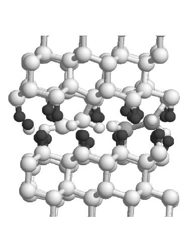
It is interesting to note that the wear debris, in the form of an ethylene molecule CH2CH2, did not undergo another chemical reaction for the remainder of the simulation. Similarly, methane CH4, ethane C2H6, and isobutane (CH3)3CH were not seen to undergo chemical reactions when introduced into a similar interface composed of hydrogen terminated (111) diamond surfaces (Sec. V C) at normal loads up to about 0.8 nN/atom (Perry and Harrison, 1996, 1997; Harrison and Perry, 1998). At higher loads, only ethane reacted. In some cases a hydrogen broke off of the ethane. The resulting free H atom then reacted with an H atom from one surface to make an H2 molecule. The remaining C2H5 could then form a carbon-carbon bond with that surface when dragged close enough to the nascent radical site. The C-C bond of the ethane was also reported to break occasionally. However, due to the proximity of the nascent methyl radicals and the absence of additional reactive species, the bond always reformed.
Sliding along the direction produced other types of reaction between surfaces with ethyl terminations. In some cases, tails of the ethyl groups became caught between hydrogen atoms on the lower surface. Continued sliding sheared the entire tail from the rest of the ethyl group, leaving a chemisorbed CH group and a free CH species. The latter group could form a bond with an existing radical site, it could shear a hydrogen from a chemisorbed ethyl group, or it could be recombined with the chemisorbed CH.
VIII Acknowledgement
Support from the National Science Foundation through Grant No. DMR-9634131 and from the German-Israeli Project Cooperation “Novel Tribological Strategies from the Nano to Meso Scales” is greatfully acknowledged. We thank Gang He, Marek Cieplak, Miguel Kiwi, Jean-Louis Barrat, Patricia McGuiggan and especially Judith Harrison for providing comments on the text. We also thank Jean-Louis Barrat for help in improving the density oscillation data in Fig. 9, and Peter A. Thompson for many useful conversations and for his role in creating Fig. 14.
-
Abraham, F. F. (1978), “The interfacial density profile of a Lennard-Jones fluid in contact with a (100) Lennard-Jones wall and its relationship to idealized fluid/wall systems: A Monte Carlo simulation”, J. Chem. Phys. 68, 3713–3716.
-
Ackerson, B. J., Hayter, J. B., Clark, N. A., and Cotter, L. (1986), “Neutron scattering from charge stabilized suspensions undergoing shear”, J. Chem. Phys. 84, 2344–2349.
-
Allen, M. P. and Tildesley, D. J. (1987), Computer Simulation of Liquids, Clarendon Press, Oxford.
-
Aubry, S. (1979), “The New Concept of Transitions by Breaking of Analyticity in a Crystallographic Model”, in Solitons and Condensed Matter Physics (Bishop, A. R. and Schneider, T., eds.), pp. 264–290, Springer-Verlag, Berlin.
-
Aubry, S. (1983), “The Twist Map, The Extended Frenkel-Kontorova Model and the Devil’s Staircase”, Physica D 7, 240–258.
-
Bak, P. (1982), “Commensurate phases, incommensurate phases and the devil’s staircase”, Rep. Progr. Phys. 45, 587–629.
-
Baljon, A. R. C. and Robbins, M. O. (1996), “Energy Dissipation During Rupture of Adhesive Bonds”, Science 271, 482–484.
-
Baljon, A. R. C. and Robbins, M. O. (1997), “Stick-Slip Motion, Transient Behavior, and Memory in Confined Films”, in Micro/Nanotribology and Its Applications (Bhushan, B., ed.), pp. 533–553, Kluwer, Dordrecht.
-
Barrat, J.-L. and Bocquet, L. (1999a), “Large Slip Effect at a Nonwetting Fluid-Solid Interface”, Phys. Rev. Lett. 82, 4671–4674.
-
Barrat, J.-L. and Bocquet, L. (1999b), “Influence of wetting properties on hydrodynamic boundary conditions at a fluid/solid interface”, Faraday Discuss. 112, 1–9.
-
Batista, A. A. and Carlson, J. M. (1998), “Bifurcations from steady sliding to stick slip in boundary lubrication”, Phys. Rev. E 57, 4986–4996.
-
Belak, J. and Stowers, I. F. (1992), “The Indentation and Scraping of a Metal Surface: A Molecular Dynamics Study”, in Fundamentals of Friction: Macroscopic and Microscopic Processes (Singer, I. L. and Pollock, H. M., eds.), pp. 511–520, Kluwer Academic Publishers, Dordrecht.
-
Binder, K. (1995), Monte Carlo and Molecular Dynamics Simulations in Polymer Science, Oxford University Press, New York.
-
Bitsanis, I. and Hadziioannou, G. (1990), “Molecular dynamics simulations of the structure and dynamics of confined polymer melts”, J. Chem. Phys. 92, 3827–3847.
-
Bitsanis, I., Magda, J. J., Tirrell, M., and Davis, H. T. (1987), “Molecular dynamics of flow in micropores”, J. Chem. Phys. 87, 1733–1750.
-
Bitsanis, I., Somers, S. A., Davis, H. T., and Tirrell, M. (1990), “Microscopic dynamics of flow in molecularly narrow pores”, J. Chem. Phys. 93, 3427–3431.
-
Bocquet, L. and Barrat, J.-L. (1993), “Hydrodynamic Boundary Conditions and Correlation Functions of Confined Fluids”, Phys. Rev. Lett. 70, 2726–2729.
-
Bocquet, L. and Barrat, J.-L. (1994), “Hydrodynamic boundary conditions, correlation functions, and Kubo relations for confined fluids”, Phys. Rev. E 49, 3079–3092.
-
Bowden, F. P. and Tabor, D. (1986), The Friction and Lubrication of Solids, Clarendon Press, Oxford.
-
Braun, O. M., Bishop, A. R., and Röder, J. (1997b), “Hysteresis in the Underdamped Driven Frenkel-Kontorova Model”, Phys. Rev. Lett. 79, 3692–3695.
-
Braun, O. M., Dauxois, T., Paliy, M. V., and Peyrard, M. (1997a), “Dynamical Transitions in Correlated Driven Diffusion in a Periodic Potential”, Phys. Rev. Lett. 78, 1295–1298.
-
Braun, O. M., Dauxois, T., Paliy, M. V., and Peyrard, M. (1997c), “Nonlinear mobility of the generalized Frenkel-Kontorova model”, Phys. Rev. E 55, 3598–3612.
-
Brenner, D. W. (1990), “Empirical Potentials for Hydrocarbons for Use in Simulating the Chemical Vapor Deposition of Diamond Films”, Phys. Rev. B 42, 9458–9471.
-
Bruch, L. W., Cole, M. W., and Zaremba, E. (1997), Physical Adsorption: Forces and Phenomena, Oxford, New York.
-
Buldum, A. and Ciraci, S. (1997), “Interplay between stick-slip motion and structural phase transitions in dry sliding friction”, Phys. Rev. B 55, 12892–12895.
-
Caroli, C. and Nozieres, P. (1996), “Dry Friction as a Hysteretic Elastic Response”, in Physics of Sliding Friction (Persson, B. N. J. and Tosatti, E., eds.), pp. 27–49, Kluwer, Dordrecht.
-
Carpick, R. W. and Salmeron, M. (1997), “Scratching the Surface: Fundamental Investigations of Tribology with Atomic Force Microscopy”, Chem. Rev. 97, 1163–1194.
-
Carson, G. A., Hu, H., and Granick, S. (1992), “Molecular Tribology of Fluid Lubrication: Shear Thinning”, Tribol. Trans. 35, 405–410.
-
Chan, D. Y. C. and Horn, R. G. (1985), “The drainage of thin liquid films between solid surfaces”, J. Chem. Phys. 83, 5311–5324.
-
Cieplak, M., Smith, E. D., and Robbins, M. O. (1994), “Molecular Origins of Friction: The Force on Adsorbed Layers”, Science 265, 1209–1212.
-
Daw, M. S. and Baskes, M. I. (1984), “Embedded-Atom Method: Derivation and Application to Impurities, Surfaces, and Other Defects in Metals”, Phys. Rev. B 29, 6443–6453.
-
Dayo, A., Alnasrallay, W., and Krim, J. (1998), “Superconductivity-Dependent Sliding Friction”, Phys. Rev. Lett. 80, 1690–1693.
-
de Gennes, P. G., unpublished.
-
Demirel, A. L. and Granick, S. (1996a), “Glasslike Transition of a Confined Simple Fluid”, Phys. Rev. Lett. 77, 2261–2264.
-
Demirel, A. L. and Granick, S. (1996b), “Friction Fluctuations and Friction Memory in Stick-Slip Motion”, Phys. Rev. Lett. 77, 4330–4333.
-
Dhinojwala, A. and Granick, S., unpublished.
-
Dieterich, J. H. (1979), “Modeling of Rock Friction. 2. Simulation of Pre-Seismic Slip”, J. Geophys. Res. 84, 2169–2175.
-
Dieterich, J. H. and Kilgore, B. D. (1996), “Imaging surface contacts: power law contact distributions and contact stresses in quartz, calcite, glass and acrylic plastic”, Tectonophysics 256, 219–239.
-
Dowson, D. and Higginson, G. R. (1968), Elastohydrodynamic Lubrication, Pergamon, Oxford.
-
Dussan, E. B. (1979), “On the Spreading of Liquids on Solid Surfaces: Static and Dynamic Contact Lines”, Ann. Rev. Fluid Mech. 11, 371–400.
-
Evans, D. J. and Morriss, G. P. (1986), “Shear Thickening and Turbulence in Simple Fluids”, Phys. Rev. Lett. 56, 2172–2175.
-
Fisher, D. S. (1985), “Sliding charge-density waves as a dynamic critical phenomenon”, Phys. Rev B 31, 1396–1427.
-
Flory, P. (1988), Statistical Mechanics of Chain Molecules, Hanser Publishers, München.
-
Frank, F. C. and van der Merwe, J. H. (1949), “One-dimensional dislocations. I. Static theory”, Proc. R. Soc. A 198, 205–225.
-
Frenkel, D. and Smit, B. (1996), Understanding Molecular Simulation: From Algorithms to Applications, Academic Press, San Diego.
-
Frenkel, Y. I. and Kontorova, T. (1938), “On the Theory of Plastic Deformation and Twinning”, Zh. Eksp. Teor. Fiz. 8, 1340.
-
Gao, J., Luedtke, W. D., and Landman, U. (1995), “Nano-Elastohydrodynamics: Structure, Dynamics, and Flow in Non-uniform Lubricated Junctions”, Science 270, 605–608.
-
Gao, J., Luedtke, W. D., and Landman, U. (1996), “Nano-Elastohydrodynamics: Structure, Dynamics and Flow in Nonuniform Lubricated Junctions”, in Physics of Sliding Friction (Persson, B. N. J. and Tosatti, E., eds.), pp. 325–348, Kluwer, Dordrecht.
-
Gao, J., Luedtke, W. D., and Landman, U. (1997a), “Origins of Solvation Forces in Confined Films”, J. Phys. Chem. B 101, 4013–4023.
-
Gao, J., Luedtke, W. D., and Landman, U. (1997b), “Structure and Solvation Forces in Confined Films: Linear and Branched Alkanes”, J. Chem. Phys. 106, 4309–4318.
-
Gee, M. L., McGuiggan, P. M., Israelachvili, J. N., and Homola, A. M. (1990), “Liquid to solid transitions of molecularly thin films under shear”, J. Chem. Phys. 93, 1895–1906.
-
Georges, J. M., Millot, S., Loubet, J. L., Touck, A., and Mazuyer, D. (1993), “Surface roughness and squeezed films at molecular level”, in Thin Films in Tribology (Dowson, D., Taylor, C. M., Childs, T. H. C., Godet, M., and Dalmaz, G., eds.), pp. 443–452, Elsevier, Amsterdam.
-
Glosli, J. N. and McClelland, G. (1993), “Molecular dynamics study of sliding friction of ordered organic monolayers”, Phys. Rev. Lett. 70, 1960–1963.
-
Gopal, A. D. and Durian, D. J. (1995), “Nonlinear Bubble Dynamics in a Slowly Driven Foam”, Phys. Rev. Lett. 75, 2610–2614.
-
Granick, S. (1992), “Motions and Relaxations of Confined Liquids”, Science 253, 1374–1379.
-
Greenwood, J. A. and Williamson, J. B. P. (1966), “Contact of nominally flat surfaces”, Proc. Roy. Soc. A 295, 300–319.
-
Grest, G. S. and Kremer, K. (1986), “Molecular dynamics simulations for polymers in the presence of a heat bath”, Phys. Rev. A 33, 3628–3631.
-
Grüner, G. (1988), “The dynamics of charge-density waves”, Rev. Mod. Phys. 60, 1129–1181.
-
Grüner, G., Zawadowski, A., and Chaikin, P. M. (1981), “Nonlinear Conductivity and Noise due to Charge-Density-Wave Depinning in NbSe3”, Phys. Rev. Lett. 46, 511–517.
-
Gyalog, T., Bammerlin, M., Lüthi, R., Meyer, E., and Thomas, H. (1995), “Mechanism of Atomic Friction”, Europhys. Lett. 31, 269–274.
-
Hammerberg, J. E., Holian, B. L., Röder, J., Bishop, A. R., and Zhou, J. J. (1998), “Nonlinear dynamics and the problem of slip at material interfaces”, Physica D 123, 330–340.
-
Hannon, L., Lie, G. C., and Clementi, E. (1988), “Micro-Hydrodynamics”, J. Stat. Phys. 51, 965–979.
-
Harrison, J. A. and Brenner, D. W. (1994), “Simulated Tribochemistry: An Atomic-Scale View of the Wear of Diamond”, J. Am. Chem. Soc. 116, 10399–10402.
-
Harrison, J. A., Brenner, D. W., White, C. T., and Colton, R. J. (1991), “Atomistic Mechanisms of Adhesion and Compression of Diamond Surfaces”, Thin Solid Films 206, 213–219.
-
Harrison, J. A. and Perry, S. S. (1998), “Friction in the Presence of Molecular Lubricants and Solid/Hard Coatings”, MRS Bull. 23(6), 27–31.
-
Harrison, J. A., Stuart, S. J., and Brenner, D. W. (1999), “Atomic-Scale Simulation of Tribological and Related Phenomena”, in Handbook of Micro/Nanotribology (Bhushan, B., ed.), pp. 525–594. CRC Press, Boca Raton.
-
Harrison, J. A., White, C. T., Colton, R. J., and Brenner, D. W. (1992a), “Nanoscale Investigation of Indentation, Adhesion and Fracture of Diamond (111) Surfaces”, Surf. Sci. 271, 57–67.
-
Harrison, J. A., White, C. T., Colton, R. J., and Brenner, D. W. (1992b), “Molecular-Dynamic Simulations of Atomic-Scale Friction of Diamond Surfaces”, Phys. Rev. B 46, 9700–9708.
-
Harrison, J. A., White, C. T., Colton, R. J., and Brenner, D. W. (1993), “Effects of Chemically-Bound, Flexible Hydrocarbon Species on the Frictional Properties of Diamond Surfaces”, J. Phys. Chem. 97, 6573–6576.
-
Hayward, I. P. (1991), “Friction and Wear Properties of Diamonds and Diamond Coatings”, Surf. Coat. Tech. 49, 554–559.
-
He, G., Müser, M. H., and Robbins, M. O. (1999), “Adsorbed Layers and the Origin of Static Friction”, Science 284, 1650–1652.
-
He, G. and Robbins, M. O., unpublished.
-
Heinbuch, U. and Fischer, J. (1989), “Liquid flow in pores: Slip, no-slip, or multilayer sticking”, Phys. Rev. A 40, 1144–1146.
-
Heslot, F., Baumberger, T., Perrin, B., Caroli, B., and Caroli, C. (1994), “Creep, stick-slip, and dry-friction dynamics: Experiments and a heuristic model”, Phys. Rev. E 49, 4973–4988.
-
Hirano, M. and Shinjo, K. (1990), “Atomistic locking and friction”, Phys. Rev. B 41, 11837–11851.
-
Hirano, M. and Shinjo, K. (1993), “Superlubricity and frictional anisotropy”, Wear 168, 121–125.
-
Hirano, M., Shinjo, K., Kaneko, R., and Murata, Y. (1991), “Anisotropy of Frictional Forces in Muscovite Mica”, Phys. Rev. Lett. 67, 2642–2645.
-
Hirano, M., Shinjo, K., Kaneko, R., and Murata, Y. (1997), “Observation of superlubricity by scanning tunneling microscopy”, Phys. Rev. Lett. 78, 1448–1451.
-
Hölscher, H., Schwarz, U. D., and Wiesendanger, R. (1997), “Simulation of the scan process in friction force microscopy”, in Materials Research Society Symposia Proceedings (Bhushan, B., ed.), pp. 379–384, Kluwer Academic Publishers, Netherlands.
-
Horn, R. G. and Israelachvili, J. N. (1981), “Direct measurement of structural forces between two surfaces in a nonpolar liquid”, J. Chem. Phys. 75, 1400–1412.
-
Hu, H.-W., Carson, G. A., and Granick, S. (1991), “Relaxation Time of Confined Liquids under Shear”, Phys. Rev. Lett. 66, 2758–2761.
-
Hu, Y.-Z., Wang, H., Guo, Y., Shen, Z.-J., and Zheng, L.-Q. (1996), “Simulations of Lubricant Rheology in Thin Film Lubrication Part II: Simulation of Couette Flow”, Wear 196, 249–253.
-
Huh, C. and Scriven, L. E. (1971), “Hydrodynamic Model of Steady Movement of a Solid/Liquid/Fluid Contact Line”, J. Colloid. Interface Sci. 35, 85–101.
-
Israelachvili, J. N. (1986), “Measurement of the Viscosity of Liquids in Very Thin Films”, J. Colloid Interface Sci. 110, 263–271.
-
Israelachvili, J. N. (1991), Intermolecular and Surface Forces, 2nd ed., Academic Press, London.
-
Jacobsen, K. W., Norskov, J. K., and Puska, M. J. (1987), “Interatomic Interactions in the effective-medium theory”, Phys. Rev. B 35, 7423–7442.
-
Jaeger, H. M., Nagel, S. R., and Behringer, R. P. (1996), “Granular solids, liquids, and gases”, Rev. Mod. Phys. 68, 1259–1273.
-
Joanny, J. F. and Robbins, M. O. (1990), “Motion of a contact line on a heterogeneous surface”, J. Chem. Phys. 92, 3206–3212.
-
Kawaguchi, T. and Matsukawa, H. (1998), “Anomalous pinning behavior in an incommensurate two-chain model of friction”, Phys. Rev. B 58, 15866–15877.
-
Khare, R., de Pablo, J. J., and Yethiraj, A. (1996), “Rheology of Confined Polymer Melts”, Macromolecules 29, 7910–7918.
-
Klein, J. and Kumacheva, E. (1995), “Confinement-Induced Phase Transitions in Simple Liquids”, Science 269, 816–819.
-
Koike, A. (1999), “Molecular Dynamics Study of Tribological Behavior of Confined Branched and Linear Perfluoropolyethers”, J. Phys. Chem. B 103, 4578–4589.
-
Koike, A. and Yoneya, M. (1998), “Chain Length Effects on Frictional Behavior of Confined Ultrathin Films of Linear Alkanes Under Shear”, J. Phys. Chem. B 102, 3669–3675.
-
Koplik, J., Banavar, J. R., and Willemsen, J. F. (1988), “Molecular Dynamics of Poiseuille Flow and Moving Contact Lines”, Phys. Rev. Lett. 60, 1282–1285.
-
Koplik, J., Banavar, J. R., and Willemsen, J. F. (1989), “Molecular dynamics of fluid flow at solid surfaces”, Phys. Fluids A 1, 781–794.
-
Kremer, K. and Grest, G. S. (1990), “Dynamics of Entangled Linear Polymer Melts: A Molecular-Dynamics Simulation”, J. Chem. Phys. 92, 5057–5086.
-
Krim, J., Solina, D. H., and Chiarello, R. (1991), “Nanotribology of a Kr Monolayer: A Quartz-Crystal Microbalance Study of Atomic-Scale Friction”, Phys. Rev. Lett. 66, 181–184.
-
Krim, J., Watts, E. T., and Digel, J. (1990), “Slippage of simple liquid films adsorbed on silver and gold substrates”, J. Vac. Sci. Technol. A 8, 3417–3420.
-
Krim, J. and Widom, A. (1988), “Damping of a crystal oscillator by an adsorbed monolayer and its relation to interfacial viscosity”, Phys. Rev. B 38, 12184–12189.
-
Kröger, M., Loose, W., and Hess, S. (1993), “Rheology and Structural-Changes of Polymer Melts via Nonequilibrium Molecular Dynamics”, J. Rheology 37, 1057–1079.
-
Landman, U. and Luedtke, W. D. (1989), “Dynamics of Tip-Substrate Interactions in Atomic Force Microscopy”, Surf. Sci. Lett. 210, L117–L184.
-
Landman, U. and Luedtke, W. D. (1991), “Nanomechanics and Dynamics of Tip-Substrate Interactions”, J. Vac. Sci. Technol. B 9, 414–423.
-
Landman, U., Luedtke, W. D., Burnham, N. A., and Colton, R. J. (1990), “Atomistic Mechanisms and Dynamics of Adhesion, Nanoindentation, and Fracture”, Science 248, 454–461.
-
Landman, U., Luedtke, W. D., and Gao, J. (1996), “Atomic-Scale Issues in Tribology: Interfacial Junctions and Nano-elastohydrodynamics”, Langmuir 12, 4514–4528.
-
Landman, U., Luedtke, W. D., and Ribarsky, M. W. (1989), “Structural and dynamical consequences of interactions in interfacial systems”, J. Vac. Sci. Technol. A 7, 2829–2839.
-
Landman, U., Luedtke, W. D., and Ringer, E. M. (1992), “Atomistic mechanisms of adhesive contact formation and interfacial processes”, Wear 153, 3–30.
-
Liebsch, A., Gonçalves, S., and Kiwi, M. (1999), “Electronic versus Phononic Friction of Xenon on Silver”, Phys. Rev. B 60, 5034–5043.
-
Loose, W. and Ciccotti, G. (1992), “Temperature and temperature control in nonequilibrium-molecular-dynamics simulations of the shear flow of dense liquids”, Phys. Rev. A 45, 3859–3866.
-
Lupowski, M. and van Swol, F. (1991), “Ultrathin films under shear”, J. Chem. Phys. 95, 1995–1998.
-
Magda, J., Tirrell, M., and Davis, H. T. (1985), “Molecular Dynamics of Narrow, Liquid-Filled Pores”, J. Chem. Phys. 83, 1888–1901.
-
Mak, C. and Krim, J. (1998), “Quartz-crystal microbalance studies of the velocity dependence of interfacial friction”, Phys. Rev. B 58, 5157–5159.
-
Manias, E., Bitsanis, I., Hadziioannou, G., and Brinke, G. T. (1996), “On the nature of shear thinning in nanoscopically confined films”, Europhys. Lett. 33, 371–376.
-
Matsukawa, H. and Fukuyama, H. (1994), “Theoretical study of friction: One-dimensional clean surfaces”, Phys. Rev. B 49, 17286–17292.
-
Maxwell, J. C. (1867), Philos. Trans. R. Soc. London Ser. A 170, 231.
-
McClelland, G. M. (1989), “Friction at Weakly Interacting Interfaces”, in Adhesion and Friction (Grunze, M. and Kreuzer, H. J., eds.), volume 17, pp. 1–16, Springer Verlag, Berlin.
-
McClelland, G. M. and Cohen, S. R. (1990), “Tribology at the Atomic Scale”, in Chemistry & Physics of Solid Surfaces VII (Vanselow, R. and Rowe, R., eds.), pp. 419–445, Springer Verlag, Berlin.
-
McClelland, G. M. and Glosli, J. N. (1992), “Friction at the Atomic Scale”, in Fundamentals of Friction: Macroscopic and Microscopic Processes (Singer, I. L. and Pollock, H. M., eds.), pp. 405–422, Kluwer, Dordrecht.
-
McCumber, D. E. (1968), “Effect of ac Impedance on the dc Voltage-Current Characteristics of Superconductor Weak-Link Junctions”, J. App. Phys. 39(7), 3113–3118.
-
Mundy, C. J., Balasubramanian, S., and Klein, M. L. (1996), “Hydrodynamic boundary conditions for confined fluids via a nonequilibrium molecular dynamics simulation”, J. Chem. Phys. 105, 3211–3214.
-
Müser, M. H. and Robbins, M. O., to be published.
-
Müser, M. H. and Robbins, M. O. (1999), “Condition for static friction between flat crystalline surfaces”, Phys. Rev. B 60.
-
Nasuno, S., Kudrolli, A., and Gollub, J. P. (1997), “Friction in Granular Layers: Hysteresis and Precursors”, Phys. Rev. Lett. 79, 949–952.
-
Nieminen, J. A., Sutton, A. P., and Pethica, J. B. (1992), “Static Junction Growth During Frictional Sliding of Metals”, Acta Metall. Mater. 40, 2503–2509.
-
Nordholm, S. and Haymet, A. D. J. (1980), “Generalized van der Waals Theory. I Basic Formulation and Application to Uniform Fluids”, Aust. J. Chem. 33, 2013–2027.
-
Nosé, S. (1991), “Constant Temperature Molecular Dynamics Methods”, Prog. Theor. Phys. Supp. 103, 1–46.
-
Ohzono, T., Glosli, J. N., and Fujihara, M. (1998), “Simulations of wearless friction at a sliding interface between ordered organic monolayers”, Jpn. J. Appl. Physics 37, 6535–6543.
-
Paliy, M., Braun, O. M., Dauxois, T., and Hu, B. (1997), “Dynamical phase diagram of the dc-driven underdamped Frenkel-Kontorova Chain”, Phys. Rev. E 56, 4025–4030.
-
Paul, W., Yoon, D. Y., and Smith, G. D. (1995), “An optimized united atom model for simulations of polymethylene melts”, J. Chem. Phys 103, 1702–1709.
-
Perry, M. D. and Harrison, J. A. (1996), “Molecular Dynamics Investigations of the Effects of Debris Molecules on the Friction and Wear of Diamond”, Thin Solid Films 290-291, 211–215.
-
Perry, M. D. and Harrison, J. A. (1997), “Friction between Diamond Surfaces in the Presence of Small Third-Body Molecules”, J. Phys. Chem. B 101, 1364–1373.
-
Persson, B. N. J. (1991), “Surface resistivity and vibrational damping in adsorbed layers”, Phys. Rev. B 44, 3277–3296.
-
Persson, B. N. J. (1993a), “Theory of friction and boundary lubrication”, Phys. Rev. B 48, 18140–18158.
-
Persson, B. N. J. (1993b), “Theory and Simulation of Sliding Friction”, Phys. Rev. Lett. 71, 1212–1215.
-
Persson, B. N. J. (1995), “Theory of Friction: Dynamical Phase Transitions in Adsorbed Layers”, J. Chem. Phys. 103, 3849–3860.
-
Persson, B. N. J. (1998), Sliding Friction: Physical Principles and Applications, Springer, Berlin.
-
Persson, B. N. J. and Ballone, P., unpublished.
-
Persson, B. N. J. and Nitzan, A. (1996), “Linear sliding friction: On the origin of the microscopic friction for Xe on silver”, Surf. Sci. 367, 261–275.
-
Persson, B. N. J. and Tosatti, E. (1996), “Theory of Friction: Elastic Coherence Length and Earthquake Dynamics”, in Physics of Sliding Friction (Persson, B. N. J. and Tosatti, E., eds.), pp. 179–189, Kluwer, Dordrecht.
-
Persson, B. N. J. and Volokitin, A. I. (1995), “Electronic friction of physisorbed molecules”, J. Chem. Phys. 103, 8679–8683.
-
Plischke, M. and Henderson, D. (1986), “Density Profiles and Pair Correlation - Functions of Lennard-Jones Fluids Near a Hard-Wall”, J. Chem. Phys. 84, 2846–2852.
-
Rabin, Y. and Hersht, I. (1993), “Thin Liquid Layers in Shear-Non-Newtonian Effects”, Physica A 200, 708–712.
-
Rabinowicz, E. (1965), Friction and Wear of Materials, Wiley, New York.
-
Raffi-Tabar, H., Pethica, J. B., and Sutton, A. P. (1992), “Influence of Adsorbate Monolayer on the Nano-Mechanics of Tip-Substrate Interactions”, Mater. Res. Soc. Symp. Proc. 239, 313–318.
-
Rajasekaran, E., Zeng, X. C., and Diestler, D. J. (1997), “Frictional anisotropy and the role of lattice relaxation in molecular tribology of crystalline interfaces”, in Materials Research Society Symposia Proccedings (Bhushan, B., ed.), pp. 379–384, Kluwer, Netherlands.
-
Raphael, E. and deGennes, P. G. (1989), “Dynamics of Wetting with Non-ideal Surfaces - The Single Defect Problem”, J. Chem. Phys. 90, 7577–7584.
-
Ribarsky, M. W. and Landman, U. (1992), “Structure and dynamics of normal-alkanes confined by Solid-Surfaces. 1. Stationary Crystalline Boundaries”, J. Chem. Phys. 97, 1937–1949.
-
Rigney, D. A. and Hammerberg, J. E. (1998), “Unlubricated Sliding Behavior of Metals”, MRS Bull. 23(6), 32–36.
-
Robbins, M. O. and Baljon, A. R. C. (2000), “Response of Thin Oligomer Films to Steady and Transient Shear”, in Microstructure and Microtribology of Polymer Surfaces (Tsukruk, V. V. and Wahl, K. J., eds.), pp. 91–117. American Chemical Society, Washington DC.
-
Robbins, M. O. and Krim, J. (1998), “Energy Dissipation in Interfacial Friction”, MRS Bull. 23(6), 23–26.
-
Robbins, M. O. and Mountain, R. D., unpublished.
-
Robbins, M. O. and Smith, E. D. (1996), “Connecting Molecular-Scale and Macroscopic Tribology”, Langmuir 12, 4543–4547.
-
Robbins, M. O. and Thompson, P. A. (1991), “Critical Velocity of Stick-Slip Motion”, Science 253, 916.
-
Robbins, M. O. (2000) “Jamming, Friction, and Unsteady Rheology”, in Jamming and Rheology: Constrained Dynamics on Microscopic and Macroscopic Scales, (Liu, A. J. and Nagel, S. R., eds.) Taylor and Francis, London.
-
Rozman, M. G., Urbakh, M., and Klafter, J. (1996), “Stick-Slip Motion and Force Fluctuations in a Driven Two-Wave Potential”, Phys. Rev. Lett. 77, 683–686.
-
Rozman, M. G., Urbakh, M., and Klafter, J. (1997), “Stick-slip dynamics as a probe of frictional forces”, Europhys. Lett. 39, 183–188.
-
Rozman, M. G., Urbakh, M., Klafter, J., and Elmer, F.-J. (1998), “Atomic Scale Friction and Different Phases of Motion of Embedded Molecular Systems”, J. Phys. Chem. B 102, 7924–7930.
-
Ruina, A. (1983), “Slip Instability and State Variable Friction Laws”, J. Geophys. Res. 88, 10359–10370.
-
Ryckaert, J. P. and Bellemans, A. (1978), “Molecular Dynamics of Liquid Alkanes”, Discuss. Faraday Soc. 66, 95–106.
-
Sarman, S. S., Evans, D. J., and Cummings, P. T. (1998), “Recent developments in non-Newtonian molecular dynamics”, Phys. Rep. 305, 1–92.
-
Schaich, W. L. and Harris, J. (1981), “Dynamic Corrections to van der Waals Potentials”, J. Phys. F: Met. Phys. 11, 65–78.
-
Schneider, T. and Stoll, E. (1978), “Molecular Dynamics Study of a Three-Dimensional One-Component Model for Distortive Phase Transitions”, Phys. Rev. B 17, 1302–1322.
-
Schoen, M., Cushman, J. H., Diestler, D. J., and Rhykerd, C. L. (1988), “Fluids in Micropores II: Self-Diffusion in a Simple Classical Fluid in a Slit-Pore”, J. Chem. Phys. 88, 1394–1406.
-
Schoen, M., Rhykerd, C. L., Diestler, D. J., and Cushman, J. H. (1987), “Fluids in Micropores. I. Structure of a Simple Classical Fluid in a Slit-Pore”, J. Chem. Phys. 87, 5464–5476.
-
Schoen, M., Rhykerd, C. L., Diestler, D. J., and Cushman, J. H. (1989), “Shear Forces in Molecularly Thin Films”, Science 245, 1223–1225.
-
Shinjo, K. and Hirano, M. (1993), “Dynamics of Friction: Superlubric State”, Surface Science 283, 473–478.
-
Smith, E. D., Cieplak, M., and Robbins, M. O. (1996), “The Friction on Adsorbed Monolayers”, Phys. Rev. B. 54, 8252–8260.
-
Sneddon, L., Cross, M. C., and Fisher, D. S. (1982), “Sliding Conductivity of Charge-Density Waves”, Phys. Rev. Lett. 49, 292–295.
-
Snook, I. K. and van Megen, W. (1980), “Solvation in simple dense fluids. I”, J. Chem. Phys. 72, 2907–2914.
-
Sokoloff, J. B. (1990), “Theory of energy dissipation in sliding crystal surfaces”, Phys. Rev. B 42, 760–765.
-
Srensen, M. R., Jacobsen, K. W., and Stoltze, P. (1996), “Simulations of atomic-scale sliding friction”, Phys Rev. B 53, 2101–2113.
-
Steele, W. A. (1973), “The physical interaction of gases with crystalline solids. I. Gas-solid energies and properties of isolated absorbed atoms”, Surf. Sci. 36, 317–352.
-
Stevens, M. J., Mondello, M., Grest, G. S., Cui, S. T., Cochran, H. D., and Cummings, P. T. (1997), “Comparison of shear flow of hexadecane in a confined geometry and in bulk”, J. Chem. Phys. 106, 7303–7314.
-
Stevens, M. J. and Robbins, M. O. (1993), “Simulations of shear-induced melting and ordering”, Phys. Rev. E 48, 3778–3792.
-
Stevens, M. J., Robbins, M. O., and Belak, J. F. (1991), “Shear-Melting of Colloids: A Non-Equilibrium Phase Diagram”, Phys. Rev. Lett. 66, 3004–3007.
-
Suh, N. P. (1986), Tribophysics, Prentice-Hall, Englewood Cliffs.
-
Taub, H., Torzo, G., Lauter, H. J., and S. C. Fain, J. (1991), Phase Transitions in Surface Films 2, Plenum Press, New York.
-
Thompson, P. A. and Grest, G. S. (1991), “Granular Flow: Friction and the Dilatancy Transition”, Phys. Rev. Lett. 67, 1751–1754.
-
Thompson, P. A., Grest, G. S., and Robbins, M. O. (1992), “Phase Transitions and Universal Dynamics in Confined Films”, Phys. Rev. Lett. 68, 3448–3451.
-
Thompson, P. A. and Robbins, M. O. (1989), “Simulations of Contact-Line Motion: Slip and the Dynamic Contact Angle”, Phys. Rev. Lett. 63, 766–769.
-
Thompson, P. A. and Robbins, M. O. (1990a), “Shear flow near solids: Epitaxial order and flow boundary conditions”, Phys. Rev. A 41, 6830–6837.
-
Thompson, P. A. and Robbins, M. O. (1990b), “Origin of Stick-Slip Motion in Boundary Lubrication”, Science 250, 792–794.
-
Thompson, P. A., Robbins, M. O., and Grest, G. S. (1993), “Simulations of Lubricant Behavior at the Interface with Bearing Solids”, in Thin Films in Tribology (Dowson, D., Taylor, C. M., Childs, T. H. C., Godet, M., and Dalmaz, G., eds.), pp. 347–360, Elsevier, Amsterdam.
-
Thompson, P. A., Robbins, M. O., and Grest, G. S. (1995), “Structure and Shear Response in Nanometer-Thick Films”, Israel J. of Chem. 35, 93–106.
-
Thompson, P. A. and Troian, S. M. (1997), “A general boundary condition for liquid flow at solid surfaces”, Nature 389, 360–363.
-
Tomagnini, O., Ercolessi, F., and Tosatti, E. (1993), “Microscopic Interaction between a Gold Tip and a Pb(110) Surface”, Surf. Sci. 287/288, 1041–1045.
-
Tomassone, M. S., Sokoloff, J. B., Widom, A., and Krim, J. (1997), “Dominance of Phonon Friction for a Xenon Film on a Silver (111) Surface”, Phys. Rev. Lett. 79, 4798–4801.
-
Tomlinson, G. A. (1929), “A molecular theory of friction”, Phil. Mag. Series 7, 905–939.
-
Toxvaerd, S. (1981), “The structure and thermodynamics of a solid-fluid interface”, J. Chem. Phys. 74, 1998–2008.
-
Tschöp, W., Kremer, K., Batoulis, J., Bürger, T., and Hahn, O. (1998a), “Simulation of polymer melts. I. Coarse graining procedure for polycarbonates”, Acta Polym. 49, 61–74.
-
Tschöp, W., Kremer, K., Batoulis, J., Bürger, T., and Hahn, O. (1998b), “Simulation of polymer melts. II. From coarse grained models back to atomistic description”, Acta Polym. 49, 75–79.
-
Tutein, A. B., Stuart, S. J., and Harrison, J. A. (2000), “Indentation Analysis of Linear-Chain Hydrocarbon Monolayers Anchored to Diamond”, J. Phys. Chem. B YY, xx–xx.
-
Urbakh, M., Daikhin, L., and Klafter, J. (1995), “Dynamics of Confined Liquids Under Shear”, Phys. Rev. E 51, 2137–2141.
-
Veje, C. T., Howell, D. W., and Behringer, R. P. (1999), “Kinematics of a two-dimensional granular Couette experiment at the transition to shearing”, Phys. Rev. E 59, 739–745.
-
Volmer, A. and Natterman, T. (1997), “Towards a Statistical Theory of Solid Dry Friction”, Z. Phys. B 104, 363–371.
-
Weiss, M. and Elmer, F.-J. (1996), “Dry Friction in the Frenkel-Kontorova-Tomlinson Model: Static Properties”, Phys. Rev. B 53, 7539–7549.
-
Xia, T. K., Ouyang, J., Ribarsky, M. W., and Landman, U. (1992), “Interfacial Alkane Films”, Phys. Rev. Lett. 69, 1967–1970.
-
Yoshizawa, H. and Israelachvili, J. N. (1993), “Fundamental Mechanisms of Interfacial Friction. 1. Stick-Slip Friction of Spherical and Chain Molecules”, J. Phys. Chem. 97, 11300–11313.